1989 MITSUBISHI GALANT air bleeding
[x] Cancel search: air bleedingPage 58 of 1273
II-8ENGINE
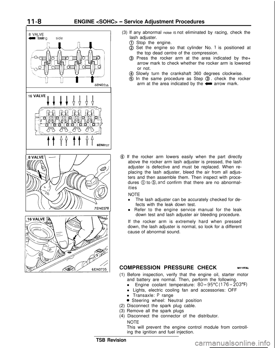
8 VALVE
W Tlmlng belt side
il6
16
727
(3) If any abnormal noise IS not eliminated by racing, check the
lash adjuster.
@ Stop the engine.
@ Set the engine so that cylinder No. 1 is positioned at
the top dead centre of the compression.
@ Press the rocker arm at the area indicated by the+ arrow mark to check whether the rocker arm is lowered
or not.
@ Slowly turn the crankshaft 360 degrees clockwise.
@ In the same procedure as Step 0, check the rocker
arm at the area indicated by the
0 arrow mark.
@ If the rocker arm lowers easily when the part directly
above the rocker arm lash adjuster is pressed, the lash
adjuster is defective and must be replaced. When re-
placing the lash adjuster, bleed the air from all adjus-
ters and then assemble them. Then inspect with proce-
dures
@ to 0, and confirm that there are no abnormal-
ities
NOTE
lThe lash adjuster can be accurately checked for de-
fects with the leak down test.
l Refer to the engine service manual for the leak down test and lash adjuster air bleeding procedure.
If the rocker arm is extremely hard when pressed
down, the lash adjuster is normal, so look for a different
cause of abnormal sound.
COMPRESSION PRESSURE CHECK
MllFFAL
(1) Before inspection, verify that the engine oil, starter motor and battery are normal. Then, perform the following.
l Engine coolant temperature:
80- 95°C
(176- 203°F)
l Lights, electric cooling fan and accessories: OFF
l Transaxle:
P range
0 Steering wheel: Neutral position
(2) Disconnect the spark plug cable.
(3) Remove all the spark plugs
(4) Disconnect the connector of the distributor.
NOTE
This will prevent the engine control module from controll- ing the ignition and fuel injection.
TSB Revision
Page 108 of 1273
11-58ENGINE
4 Timing belt sideI
6EN0515
(3) lf
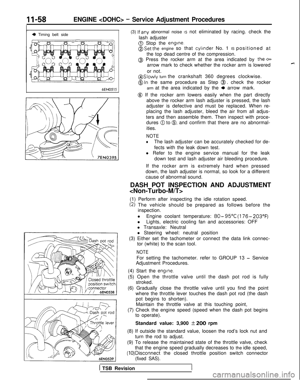
any abnormal noise IS not eliminated by racing. check the
lash adjuster
@ Stop the engine.
@ Set the engine so that cylinder
No. 1 IS positioned at
the top dead centre of the compression.
@ Press the rocker arm at the area indicated by the+
arrow mark to check whether the rocker arm is lowered
or not.
@ Slowly turn the crankshaft 360 degrees clockwise.
@ ln the same procedure as Step 0, check the rocker
arm at the area indicated by the
4 arrow mark.
@ If the rocker arm lowers easily when the part directly above the rocker arm lash adjuster is pressed, the lash
adjuster is defective and must be replaced. When re- placing the lash adjuster, bleed the air from all adjus-
ters and then assemble them. Then inspect with proce- dures
@I to 0, and confirm that there are no abnormal-
ities.
NOTE
lThe lash adjuster can be accurately checked for de-
fects with the leak down test.
l Refer to the engine service manual for the leak
down test and lash adjuster air bleeding procedure.
If the rocker arm is extremely hard when pressed
down, the lash adjuster is normal, so look for a different
cause of abnormal sound.
DASH POT INSPECTION AND ADJUSTMENT
(1) Perform after inspecting the idle rotation speed.
(2) The vehicle should be prepared as follows before the inspection.
l Engine coolant temperature:
80- 95°C
(176- 203°F)
lLights, electric cooling fan and accessories: OFF
l Transaxle: Neutral
l Steering wheel: neutral position
(3) Either set the tachometer or connect the data link connec- tor (white) to the scan tool.
NOTE
For setting the tachometer. refer to GROUP 13 - Service
Adjustment Procedures.
(4) Start the
engine.
(5) Open the throttle valve until the dash pot rod is fully
stroked.
(6) Gradually close the throttle valve until you find the point where the throttle lever touches the dash pot rod (the dashpot begins to shorten).
Maintain the throttle valve at this touching point,
(7) Check the engine speed (speed when the dash pot begins to operate).
Standard value: 3,900
f 200 rpm
(8) If outside the standard value, loosen the rod’s lock nut and turn the rod to adjust.
(9) To release the maintained state of the throttle valve, check that the engine speed gradually decreases to the idle speed, (10)Disconnect
the closed throttle position switch connector
(fixed SAS).
1 TSB Revision
Page 651 of 1273
21-1
CLUTCH
CONTENTS
CLUTCH CONTROL. . . . . . . . . . . . . . . . . . . . . . . . . . . . . . . . . . . . \
. . . . .10SPECIFICATIONS. . . . . . . . . . . . . . . ..*...........................2
CLUTCHMASTER CYLINDER. . . . . . . . . . . . . . . . . . . . . . . .12GeneralSpecifications. . . . . . . . . . . . . . . . . . . . . . . . . . . . . . . . . .2
CLUTCH PEDALLubricants . . . . . . . . . . . . . . . . . . . . . . . . . . . . . . .\
. . . . . . . . . . . . . . . . . . . . . . .3. . . . . . . . . . . . . . . . . . . . . . . . . . . . . . . . . . . . \
. . . . . . . . . .7
ServiceSpecifications. . . . . . . . . . . . . . . . . . . . . . . . . . . . . . . . . . .2
CLUTCHRELEASECYLINDER. . . . . . . . . . . . . . . . . . . . . . .13Torque Specifications . . . . . . . . . .._.......................3
SERVICE ADJUSTMENT PROCEDURES . . . . . . . 5TROUBLESHOOTING. . . . . . . . . . . . . . . . . . . . . . . . . . . . . . . . . . . . \
. .4
Bleeding. . . . . . . . . . . . . . . . . . . . . . . . . . . . . . . .6Clutch chatters
Clutch Pedal Inspection and Adjustment . . . .
5Clutch noise
Clutch pedal feels “heavy”
Clutch slips
Gear shift malfunction
CAUTION When
servicing clutch assemblies or com-
ponents for vehicles with SOHC engine
(Up to 1991 models), do NOT create dust
by sanding or by cleaning clutch parts
with a dry brush or with compressed air.
(A water dampened cloth should be used).
The clutch disc contains “Asbestos Fibers”
which can become airborne if dust is
created during service operations. Breath-
ing dust containing “Asbestos Fibers”
may cause serious bodily harm.
Page 656 of 1273
21-6CLUTCH - Service Adjustment Procedures
5.If the clutch pedal free play and the distance between the
clutch pedal and the firewall when the clutch is disengaged
do not agree with the standard values, it is probably the
result of either air in the hydraulic system or a faulty master
cylinder or clutch. Bleed the air, or disassemble and inspect
the master cylinder or clutch.
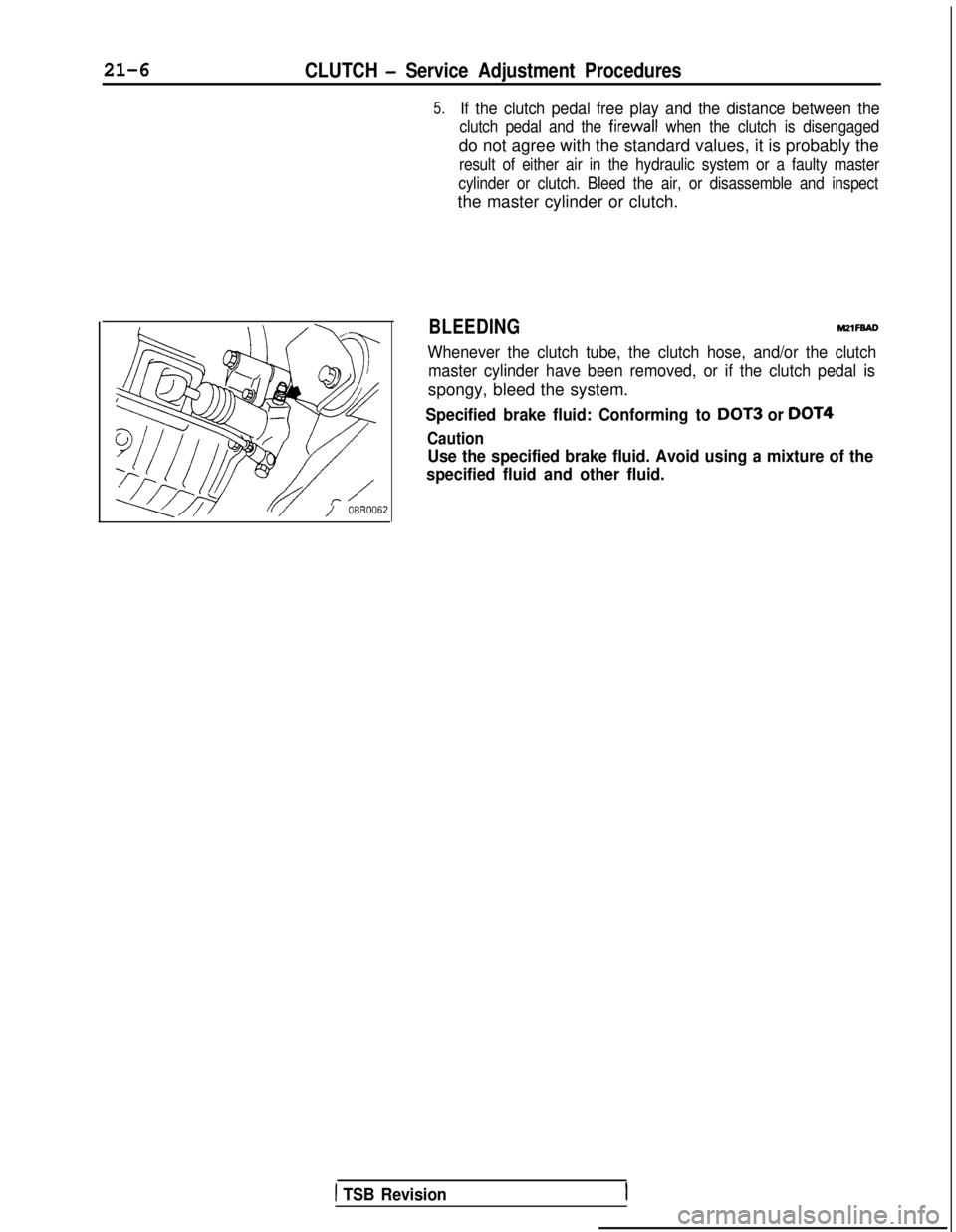
BLEEDINGM2lFBAD
Whenever the clutch tube, the clutch hose, and/or the clutch master cylinder have been removed, or if the clutch pedal is
spongy, bleed the system.
Specified brake fluid: Conforming to DOT3 or DOT4
Caution
Use the specified brake fluid. Avoid using a mixture of the
specified fluid and other fluid.
1 TSB Revision
Page 913 of 1273
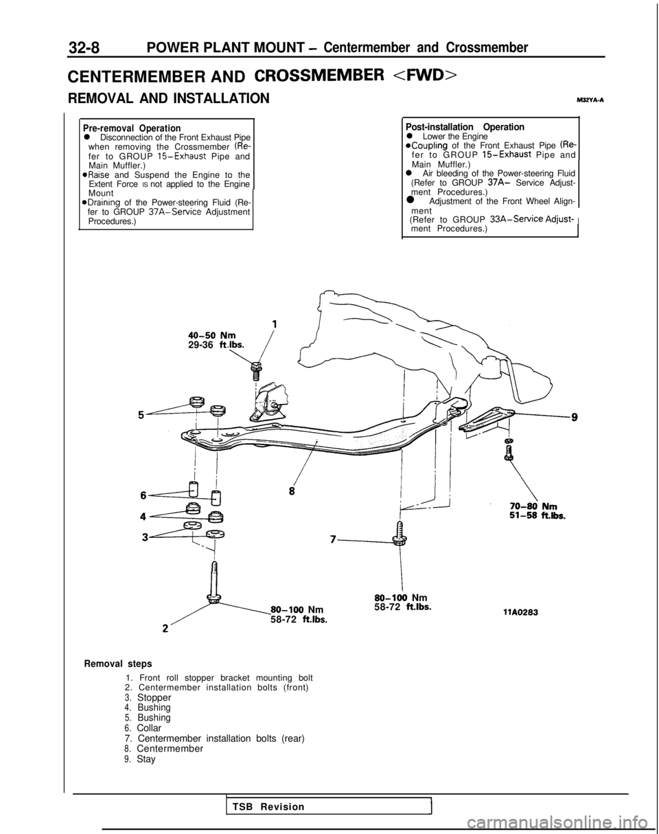
32-8POWER PLANT MOUNT -Centermember and Crossmember
CENTERMEMBER ANDCROSSMEMBER
REMOVAL AND INSTALLATIONM3ZYA-A
Pre-removal Operationl Disconnection of the Front Exhaust Pipe
when removing the Crossmember (Re-fer to GROUP 15-Exhaust Pipe and
Main Muffler.) aRaise
and Suspend the Engine to the
Extent Force IS not applied to the Engine
Mount
@Draining of the Power-steering Fluid (Re-
fer to GROUP 37A-Service Adjustment
Procedures.)
40-50 N29-36 ft
Post-installation Operationl Lower the Engine*Coupling of the Front Exhaust Pipe (Re-fer to GROUP 15-Exhaust Pipe and
Main Muffler.)
l Air bleeding of the Power-steering Fluid
(Refer to GROUP
37A- Service Adjust-
ment Procedures.)
l Adjustment of the Front Wheel Align-
ment
(Refer to GROUP
33A-Service Adjust-Iment Procedures.)
80-100 Nm
58-72 ft.lbs.
80-100 Nm
58-72 ft.lbs.
Removal steps
1. Front roll stopper bracket mounting bolt
2. Centermember installation bolts (front)
3.Stopper4.Bushing5.Bushing6.Collar
7. Centermember installation bolts (rear)
8.Centermember9.Stay llA0283
TSB Revision
Page 917 of 1273
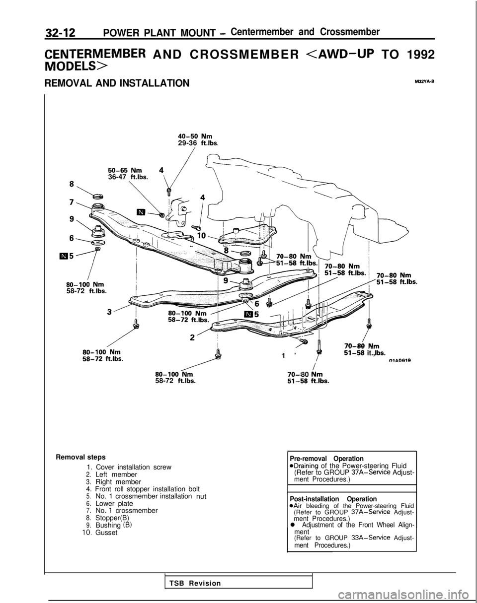
32-12POWER PLANT MOUNT -Centermember and Crossmember
C&Et;;rSM>EMBER AND CROSSMEMBER
40-50 Nm29-36 ft.lbs.
50-65 Nm36-47 ft.lbs.80-100
Nm58-72 ftlbs.
80-100
Nm58-72 ft.lbs.
1
’
--
--_ii-58 it.,tTlAO619I 70-r
80 km51-58klbs.
Removal steps
1. Cover installation screw
2.Left member3.Right member
4. Front roll stopper installation bolt
5.No. 1 crossmember installation
nut6.Lower plate7.No. 1 crossmember8.Stopper(B)9.Bushing (B)10.Gusset
Pre-removal OperationeDraining of the Power-steering Fluid
(Refer to GROUP 37A-Service
Adjust-
ment Procedures.)
Post-installation Operation@Air bleeding of the Power-steering Fluid
(Refer to GROUP 37A-Service Adjust-ment Procedures.)l Adjustment of the Front Wheel Align-
ment
(Refer to GROUP 33A-Service Adjust-ment Procedures.)
TSB Revision
Page 1122 of 1273
35-1
SERVICE BRAKES
CONTENTSM35AA-
ANTI-LOCK BRAKING SYSTEM
TROUBLESHOOTING............................
.
15
BRAKE BOOSTER
................................
.
85
BRAKE FLUID PRESSURE SWITCH
.
133
BRAKE LINE
......................................
.
87
BRAKE PEDAL...................................
.
76
ELECTRONIC CONTROL UNIT
......................134
FRONT DISC BRAKE
............................
.
94
G-SENSOR
.
132
HYDRAULIC UNIT
. . . . . . . . . . . . . . . . . . . . . . 121
MASTER CYLINDER.............................
.
81
REAR BRAKE WHEEL CYLINDER...............
.
111
REAR DISC BRAKE..............................
.
114
REAR DRUM BRAKE.........
.
,.................
.
108
SERVICE ADJUSTMENT PROCEDURES.......
.
53
A.B.S. Power Relay Check
.....................
.
74
Anti-lock Braking System (A.B.S.) Check (Checking by the A.B.S. Warning Light) .........
68
Bleeding .........................................
57
Brake Booster Operating Inspection
...........
.
54
Brake Drum Inside Diameter Check
...........
.
67
Brake Fluid Level Sensor Check ................
54
Brake Fluid Pressure Switch Check
Brake Lining and Brake Drum Connection
Check _. _. . _. _. . .67
Brake Lining Thickness Check ..............
.
Brake Pedal Inspection and Adjustment .....
Check Valve Operation Check ...........
.:...
Delay Valve Check
.
Flat Battery Remedy .........................
Front Disc Brake Pad Check and
Replacement ..................................
inspection of Hydraulic Unit ..................
Measurement of Wheel Speed Sensor
Output Voltage ...............................
Proportioning Valve Function. Test ...........
Rear Brake Disc Run-out Check .............
Rear Brake Disc Run-out Correction .........
Rear Brake Disc Thickness Check ...........
Rear Disc Brake Pad Check and
Replacement ..................................
Run-out Check ................................ . 67
. 53
54
74
. 75
59
70
. 69
5
6
. 66
. 66
. 66
. 65
. 63
Run-out Correction . . . . . . . . . . .
64
Thickness Check. . . . . . . . . . . . . .
Wheel Speed Sensor Output Voltage Check .
SPECIAL TOOLS.................................
.
11
SPECIFICATIONS................................
.
2
General Specifications
..........................
.
2
Lubricants
......................................
.
11
Sealant and Adhesives
.........................
.
11
Service Specifications
..........................
.
7
Torque Specifications
..........................
.
10
TROUBLESHOOTING............................
.
12
WHEEL SPEED SENSOR
.
126
CAUTION
When servicing brake assemblies or components, do not create dust by san\
ding, grinding or by cleaning
brake parts with a
dry brush or with compressed air. A WATER DAMPENED CLOTH SHOULD BE USED.
Many brake components contain asbestos fibers which can become air-borne\
if dust is created during
service operations. Breathing dust which contains asbestos fibers can ca\
use
seriouj bodily harm.
Page 1178 of 1273
SERVICE, BRAKES - Service Adjustment Procedures35-57
4
1
2314AQ456
FWD
Delay valve L
flc ’
-c
i1
L
3
14AO4l
mit
14RD120
AWD
51
6 2414AO4E
BLEEDING
Because the master cylinder employed is the type without the
check valve, air should be bled from the master cylinder by
following the procedures described below (if there is no brake
fluid in the master cylinder).
(1) Disconnect the brake tube from the master cylinder.
(2) Two persons’ should conduct the air bleeding, one person
slowly depressing the brake pedal and holding the pedal
depressed.
(3) In this condition, the other person should use a finger to close the outlet part of the master cylinder, and then the
first person should release the brake pedal.
(4) Steps (2) and (3) should be repeated three or four times, and then the master cylinder should be filled with brake
fluid to the specified level.
I(]OTE
The air is completely bled from the master cylinder by
steps (1) to (4).
(5) Connect the brake tube to the master cylinder.
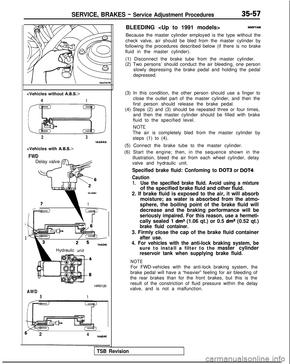
(6) Start the engine; then, in the sequence shown in the illustration, bleed the air from each wheel cylinder, delay
valve and hydraulic unit.
Specified brake fluid: Confoming to DOT3 or DOT4
Caution
1.Use the specified brake fluid. Avoid using a mixture
of the specified brake fluid and other fluid.
2. If brake fluid is exposed to the air, it will absorb moisture; as water is absorbed from the atmo-
sphere, the boiling point of the brake fluid will
decrease and the braking performance will be
seriously impaired. For this reason, use a hermeti-
cally sealed 1 dms (1.06 qt.) or 0.5 dms (0.52 qt.)
brake fluid container.
3. Firmly close the cap of the brake fluid container
after use.
4. For vehicles with the anti-lock braking system, be
sure to install a filter to the master cylinder
reservoir tank when supplying brake fluid.
NOTE
For FWD-vehicles with the anti-lock braking system, the
brake pedal will have a “heavier” feeling for air bleeding of
the rear brakes than for the front brakes, but this is the
result of the constriction of fluid pressure within the delay
valve, and is not a malfunction.
1 TSB Revision