1989 MITSUBISHI GALANT air condition
[x] Cancel search: air conditionPage 6 of 1273
00-4GENERAL - How to Use This Manual
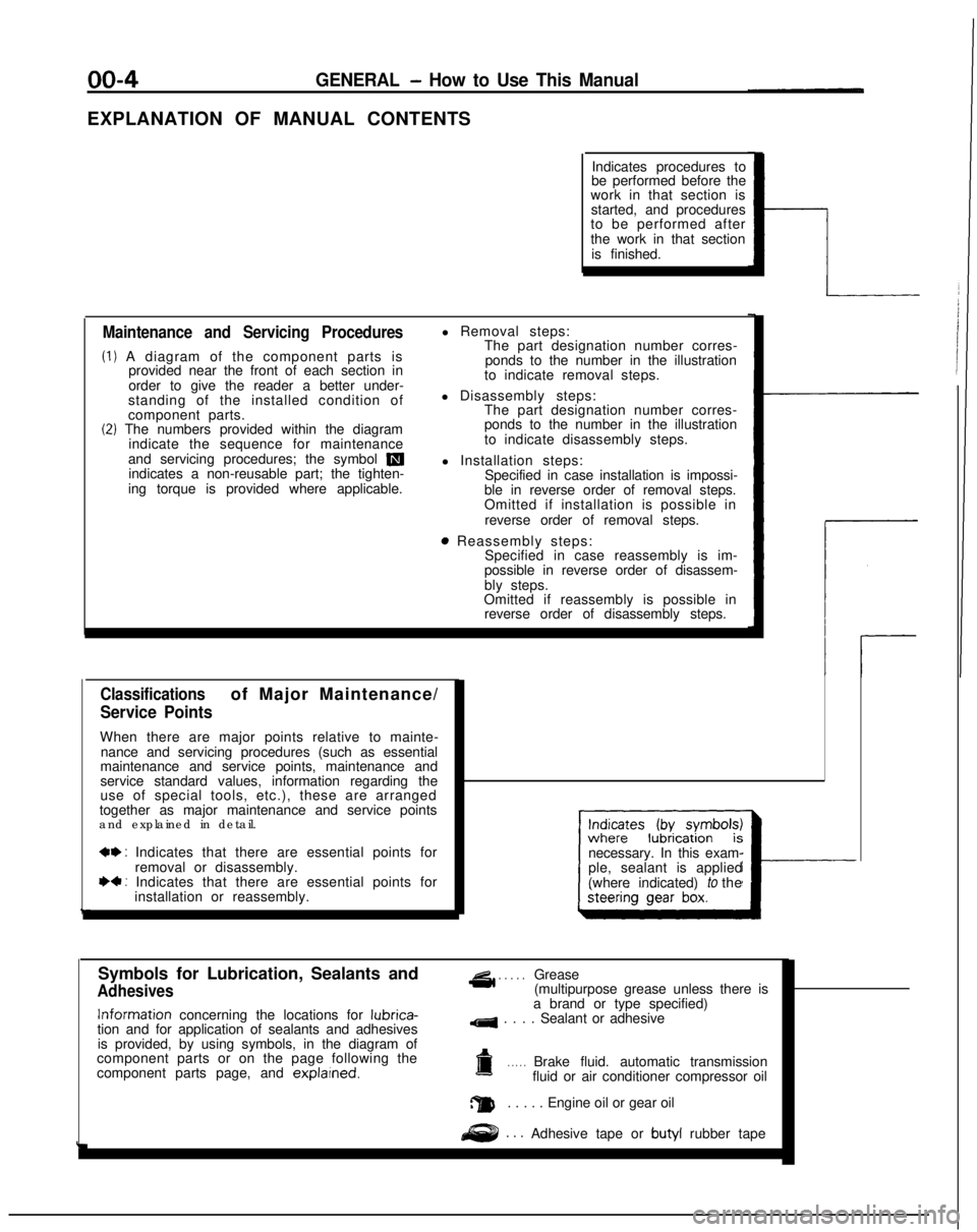
EXPLANATION OF MANUAL CONTENTSIndicates procedures to
be performed before the
work in that section is
started, and procedures
to be performed after
the work in that section
is finished.
Maintenance and Servicing Procedures
(1) A diagram of the component parts is provided near the front of each section in
order to give the reader a better under-
standing of the installed condition of
component parts.
(2) The numbers provided within the diagram indicate the sequence for maintenance
and servicing procedures; the symbol
mindicates a non-reusable part; the tighten-
ing torque is provided where applicable. l Removal steps:
The part designation number corres-
ponds to the number in the illustration
to indicate removal steps.
l Disassembly steps: The part designation number corres-
ponds to the number in the illustration
to indicate disassembly steps.
l Installation steps: Specified in case installation is impossi-
ble in reverse order of removal steps.
Omitted if installation is possible in
reverse order of removal steps.
8 Reassembly steps: Specified in case reassembly is im-
possible in reverse order of disassem-
bly steps.
Omitted if reassembly is possible in reverse order of disassembly steps.
Classificationsof Major Maintenance/
Service Points
When there are major points relative to mainte-
nance and servicing procedures (such as essential
maintenance and service points, maintenance and
service standard values, information regarding the
use of special tools, etc.), these are arranged
together as major maintenance and service points
and explained in detail.
*+ : Indicates that there are essential points for
removal or disassembly.
I)+ : Indicates that there are essential points forinstallation or reassembly. necessary. In this exam-
ple, sealant is applied
(where indicated) to the
I---
Symbols for Lubrication, Sealants and
Adhesives
4 . . . . .Grease
(multipurpose grease unless there is Information
concerning the locations for lubrica-
tion and for application of sealants and adhesives
is provided, by using symbols, in the diagram of
component parts or on the page following the
component parts page, and explarned.
a brand or type specified)
4 . . . . Sealant or adhesive
a. . . . .Brake fluid. automatic transmission
fluid or air conditioner compressor oil
a. . . . . Engine oil or gear oil
. . .Adhesive tape or butyl
rubber tape
Page 8 of 1273
00-6GENERAL - How to Use This Manual
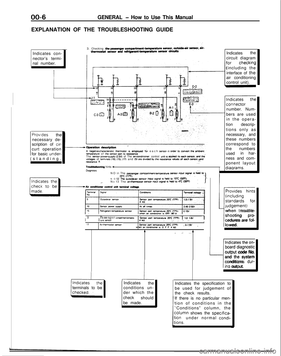
EXPLANATION OF THE TROUBLESHOOTING GUIDEIndicates con-
nector’s termi-
nal number. 3. Checking
the pasmngw compartment-twnpwatu* UnSO!. ~ F, ah-thermo8tat sensor and refdgwant-tempnaturs sensor ufalitsIndicates
the
circuit diagram
(including the interface of the
air conditioning
control unit).
number. Num-
bers are used temperawe
of
the Sensor pm
to resistanceeach sensor t? order to convest lb+ amben
The sense, power-supply l2.W of The atrcOnd,f,oner control unit s aD&d~to each SmSOt snd lhevoltages of te,mmaIs 116). (151. (17) and (51 are
dwded by the reslstme va!ueS.of each ““Freelstance R..
TmuMnhooting
hints *Dtagnoss
in the opera
-
tion descrip-
tions only as necessary, and
these numbers
correspond to
the numbers
used in har-
ness and com-
ponent layout diagrams.Provides
the
necessary de-
scription of
cir-
curt operation
for basic under-
(standing.
NO
1, The passenger cPrrlpmme”l-lemperatu4
-r tnput sigrml is
hid toZ’C (77-F).,, “”NO 1’2 The ou~sde.ar sensor
inpu
srgnal IS held to WC (5IpF).._N
O 13 The air#t,?,mpSf~ SenSO, VlPut SlgMl 6 t+ 10 4% G33-F):I-Airwndtlimluconhdunittwmirutwtmge
~~
I16I lYle *“MIPassenger com,wnme”t-tawa.1 sensor Parr lem,mat”r~ 25-c OFFI 7 to WV1,‘W. _: ,. L. .LI17A~r.,hermos,at seworsensor
Pm
remoeraure 2% 177% WM”
m cQndlt*Ow IS OFF 1 Lo, o-‘l,W
,
terminals to be 4
_
.: ._. 4
-hiIndicates
the
conditions un-
der which the
check should
be made. Provides hints
(including
standards for
I-- judgement)
when trouble-
shooting
pro-
cedures are fol-
lowed.
Indicates the on-
board diagnostic
L:
output code No.
and the system
conditions
dur-
ina output.
Indicates the specification to
be used for judgement of
the check results.
If there is no particular men-
tion of conditions in th
e
‘Conditions” column, the column
shows the
specifica-:ionunder normal condi-
:ions.
Page 41 of 1273
GENERAL - Scheduled Maintenance Table/Maintenance Service00-39
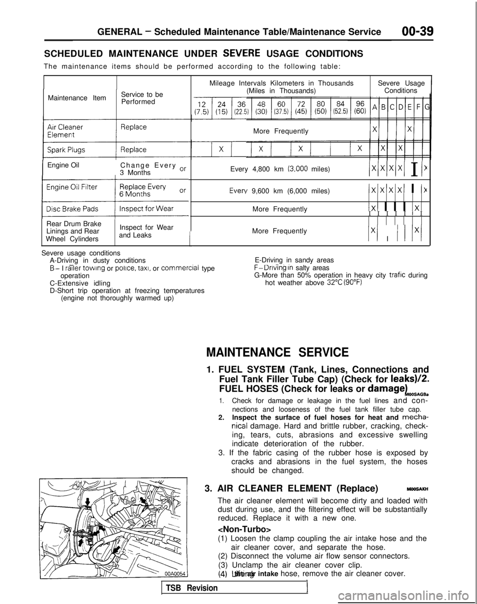
SCHEDULED MAINTENANCE UNDER SEVEiRE USAGE CONDITIONS
The maintenance items should be performed according to the following tab\
le:
Maintenance Item Service to be
Performed
IEngine Oil Change Every or
3 Months
(:z:.:a::I
Rear Drum Brake
Linings and Rear
Wheel Cylinders Inspect for Wear
and Leaks
1
Mileage Intervals Kilometers in Thousands (Miles in Thousands) Severe Usage
Conditions
More Frequently
Every 4,800 km
(3,000 miles)/xlxlx/xI I I1 Every
9,600 km (6,000 miles)
IxIxlxIxI I I>(
More Frequently1x1 I I I 1x1I I I I I I I
More Frequently
Ix1 I I I lx/
Severe usage conditions A-Driving in dusty conditions
- -B- I railer
towing or police.
taxi,
or commercial
type
operation
C-Extensive idling
D-Short trip operation at freezing temperatures (engine not thoroughly warmed up) E-Driving in sandy areas- -..F-Dnvlng In salty areas
G-More than 50% operation in heavy city trafic during
hot weather above 32°C (90°F)
MAINTENANCE SERVICE
1. FUEL SYSTEM (Tank, Lines, Connections and
Fuel Tank Filler Tube Cap) (Check for leaks)/2.
FUEL HOSES (Check for leaks or
damagekOOSnOB.
1.Check for damage or leakage in the fuel lines and con-
nections and looseness of the fuel tank filler tube cap.
2. Inspect the surface of fuel hoses for heat and mecha-
nicall damage. Hard and brittle rubber, cracking, check-
ing, tears, cuts, abrasions and excessive swelling
indicate deterioration of the rubber.
3. If the fabric casing of the rubber hose is exposed by cracks and abrasions in the fuel system, the hoses
should be changed.
3. AIR CLEANER ELEMENT (Replace)
MMlSAKH
The air cleaner element will become dirty and loaded with dust during use, and the filtering effect will be substantiallyreduced. Replace it with a new one.
(1) Loosen the clamp coupling the air intake hose and the air cleaner cover, and separate the hose.
(2) Disconnect the volume air flow sensor connectors.
(3) Unclamp the air cleaner cover clip.
(4) Lifting the air intake hose, remove the air cleaner cover.
TSB Revision1
Page 45 of 1273
GENERAL - Maintenance Service00-43
1
O.AUTOMATIC
TRANSAXLE
Inspect fluid levelMOOSSDA
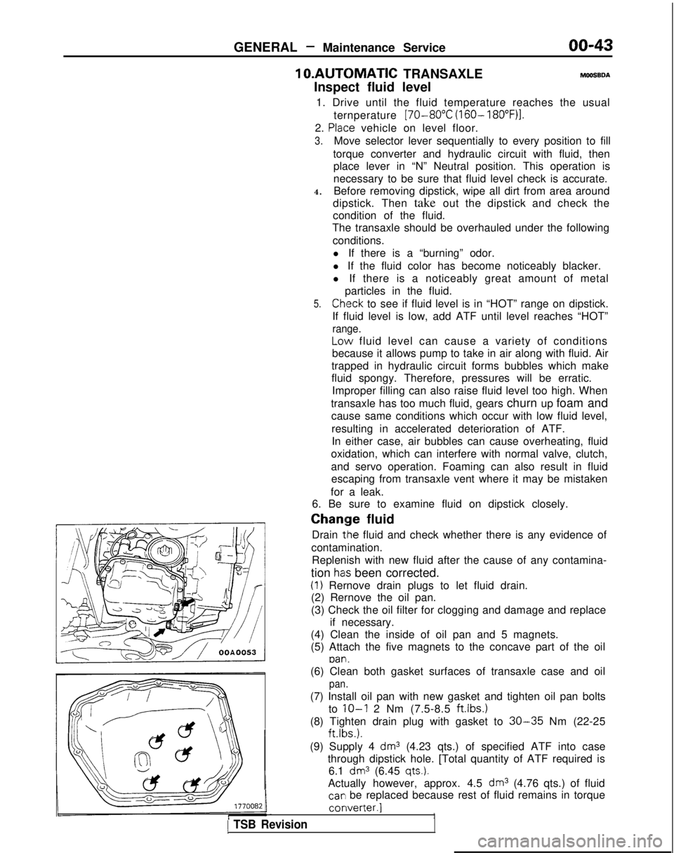
1. Drive until the fluid temperature reaches the usual ternperature
[70-80°C (160- 18O”F)I.
2. Plaice vehicle on level floor.
3.Move selector lever sequentially to every position to fill
torque converter and hydraulic circuit with fluid, then place lever in “N” Neutral position. This operation is
necessary to be sure that fluid level check is accurate.
4. Before removing dipstick, wipe all dirt from area around
dipstick. Then take out the dipstick and check the
condition of the fluid.
The transaxle should be overhauled under the following
conditions.l If there is a “burning” odor.
l If the fluid color has become noticeably blacker.
l If there is a noticeably great amount of metal particles in the fluid.
5.Chleck to see if fluid level is in “HOT” range on dipstick.
If fluid level is low, add ATF until level reaches “HOT”
range.
LO\N fluid level can cause a variety of conditions
because it allows pump to take in air along with fluid. Air
trapped in hydraulic circuit forms bubbles which make
fluid spongy. Therefore, pressures will be erratic. Improper filling can also raise fluid level too high. When
transaxle has too much fluid, gears churn up foam and cause same conditions which occur with low fluid level,
resulting in accelerated deterioration of ATF.In either case, air bubbles can cause overheating, fluid
oxidation, which can interfere with normal valve, clutch,
and servo operation. Foaming can also result in fluid escaping from transaxle vent where it may be mistaken
for a leak.
6. Be sure to examine fluid on dipstick closely. Chaqge
fluid
Drain
tlhe fluid and check whether there is any evidence of
contamination. Replenish with new fluid after the cause of any contamina-
tion
has been corrected.
(1) Rernove drain plugs to let fluid drain.
(2) Rernove the oil pan.
(3) Check the oil filter for clogging and damage and replace
if necessary.
(4) Clean the inside of oil pan and 5 magnets.
(5) Attach the five magnets to the concave part of the oil
pan.
1 TSB Revision
(6) Clean both gasket surfaces of transaxle case and oil
pan.
(7) Install oil pan with new gasket and tighten oil pan bolts
to
IO-I 2 Nm (7.5-8.5 ftlbs.)
(8) Tighten drain plug with gasket to 30-35 Nm (22-25 ft.lbs.).
(9) Supply 4
dm3 (4.23 qts.) of specified ATF into case
through dipstick hole. [Total quantity of ATF required is 6.1
dm3 (6.45 qts.).
Actually however, approx. 4.5 dm3 (4.76 qts.) of fluid
car1 be replaced because rest of fluid remains in torque converter.]
1
Page 53 of 1273
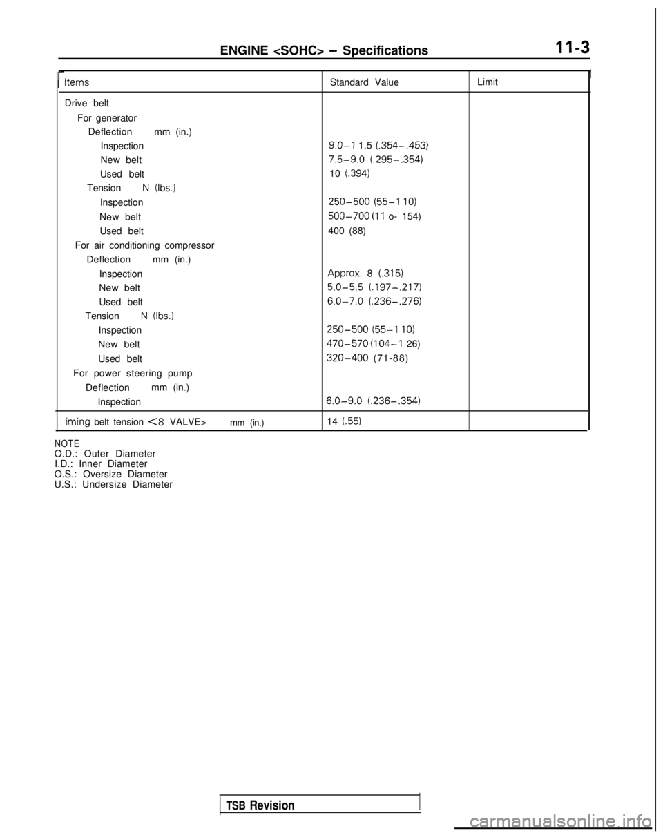
ENGINE
l-
Items
Standard ValueLimit1
Drive belt
For generatorDeflection mm (in.)
Inspection
9.0-l 1.5 (.354-,453)
New belt7.5-9.0 (.295-.354)
Used belt 10 (.394)
TensionN (Ibs.)
Inspection250-500 (55-l IO)
New belt500-700 (11 o- 154)
Used belt 400 (88)
For air conditioning compressor Deflection mm (in.)
Inspection Approx.
8
(.315)
New belt5.0-5.5 (.197-.217)
Used belt6.0-7.0 (.236-,276)
TensionN (Ibs.)
Inspection250-500 (55-l IO)
New belt470-570 (104-I 26)
Used belt
320-400 (71-88)
For power steering pump Deflection mm (in.)
Inspection
6.0-9.0 (.236-,354) iming
belt tension
<8 VALVE>mm (in.)14 (.55)
NOTE
O.D.: Outer Diameter I.D.: Inner Diameter
O.S.: Oversize Diameter
U.S.: Undersize Diameter
TSB Revision
Page 54 of 1273
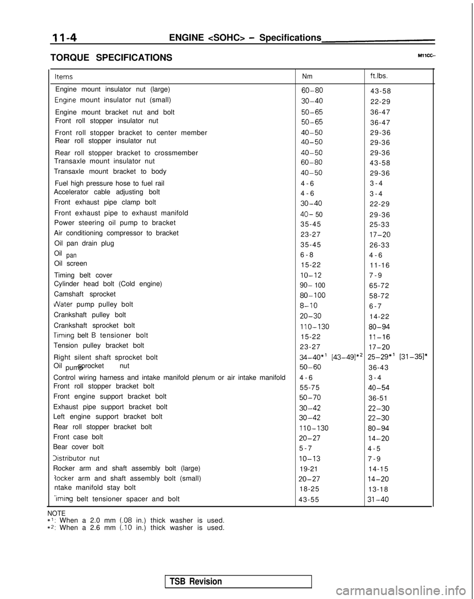
II-4ENGINE
TORQUE SPECIFICATIONS Items
Nm ft.lbs.
Engine mount insulator nut (large)
60-8043-58
Engrne mount insulator nut (small)30-4022-29
Engine mount bracket nut and bolt
50-6536-47
Front roll stopper insulator nut
50-6536-47
Front roll stopper bracket to center member
40-5029-36
Rear roll stopper insulator nut
40-5029-36
Rear roll stopper bracket to crossmember
40-5029-36
Transaxle mount insulator nut
60-8043-58
Transaxle mount bracket to body
40-5029-36
Fuel high pressure hose to fuel rail 4-
6
3-4
Accelerator cable adjusting bolt 4-63-4
Front exhaust pipe clamp bolt
30-4022-29
Front exhaust pipe to exhaust manifold
40- 5029-36
Power steering oil pump to bracket 35-4525-33
Air conditioning compressor to bracket 23-27
17-20
Oil pan drain plug35-4526-33
Oilpan6-
8
4-6
Oil screen 15-2211-16
Timing belt cover
IO-127-
9
Cylinder head bolt (Cold engine)
90- 10065-72
Camshaft sprocket
80-10058-72
dater pump pulley bolt8-106-
7
Crankshaft pulley bolt
20-3014-22
Crankshaft sprocket bolt
110-13080-94
Timrng belt B tensioner bolt 15-2211-16
Tension pulley bracket bolt 23-2717-20
Right silent shaft sprocket bolt34-40”’ [43-49]*’ 25-29” [31-351”
Oil sprocket nut pump
50-6036-43
Control wiring harness and intake manifold plenum or air intake manifold\
4-
6
3-4
Front roll stopper bracket bolt 55-75
40-54
Front engine support bracket bolt50-7036-51
Exhaust pipe support bracket bolt
30-4222-30
Left engine support bracket bolt30-4222-30
Rear roll stopper bracket bolt110-13080-94
Front case bolt20-2714-20
Bear cover bolt 5-
7
4-5
Iistributor nutIO-137-
9
Rocker arm and shaft assembly bolt (large) 19-2114-15
?ocker arm and shaft assembly bolt (small)20-2714-20
ntake manifold stay bolt
18-2513-18
-iming belt tensioner spacer and bolt
43-5531-40
NOTE*I: When a 2.0 mm (.08 in.) thick washer is used.~2: When a 2.6 mm (.I0 in.) thick washer is used.
TSB Revision
Page 60 of 1273
II-IOENGINE
(3) Remove the PCV hose from the PCV valve and attach a
vacuum gauge.
(4) Check that the negative pressure at the intake manifold
during idle revolution is normal.
Standard value:
(8 VALVE>Approx. 500 mmHg (20 in.Hg)
<16VALVE>Approx. 510 mmHg (20 in.Hg)
(5) If outside the standard value, isolate the cause by referring
to the following table and repair the fault.
Symptom
CauseRemed
y
l The vacuum gauge reading is less than l Ignition timing is retarded.l Adjust the ignition timing.
standard value, but the pointer is
stable.
l The vacuum gauge pointer swings l The gas mixture is excessivelyl Check
Multiport Fuel Injection
slowly.rich.system.
l The vacuum gauge pointer drops irre-
l The gas mixture is excessively
l Check
Multiport Fuel Injectiongularly.lean.system.
l The vacuum gauge pointer drops inter-
0 Incomplete close contact of in-0 Check and repair the valve.mittently to 30 to 160
mmHg
(1.2 to take and exhaust valve seats.
6.3 in.Hg).
l The vacuum gauge pointer drops sud-l Broken cylinder head gasketl ,Replace cylinder head gasket. denly
from the normal reading to 250 mmHg
(9.8 in.Hg). then returns to
normal.
/ OlR0175
condition.
Timina mark
‘timing mark._*-
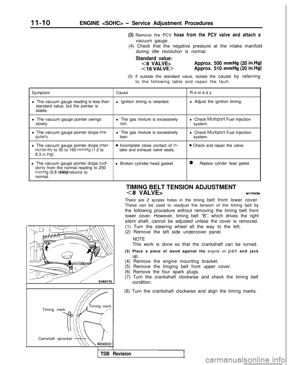
Camshaft sprocket TIMING BELT TENSION ADJUSTMENT
(8 VALVE>MllFGCEa
There are 2 access holes in the timing belt front lower cover.
These can be used to readjust the tension of the timing belt by
the following procedure without removing the timing belt front lower cover. However, timing belt “B”, which drives the right
silent shaft, cannot be adjusted unless the cover is removed. (1) Turn the steering wheel all the way to the left.
(2) Remove the left side undercover panel.
NOTE
This work is done so that the crankshaft can be turned.
(3) Place a piece of wood against the engine oil pan and jac
k
up.(4) Remove the engine mounting bracket.
(5) Remove the timging belt front upper cover.
(6) Remove the four spark plugs.
(7) Turn the crankshaft clockwise and check the timing belt
(8) Turn the crankshaft clockwise and align the timing marks.
TSB Revision1
Page 61 of 1273
ENGINE
Access
cover
,-
(0 a0
<
0 0
0 0
0
101 II0221
Access cover
Screwdriver slot
3EN075
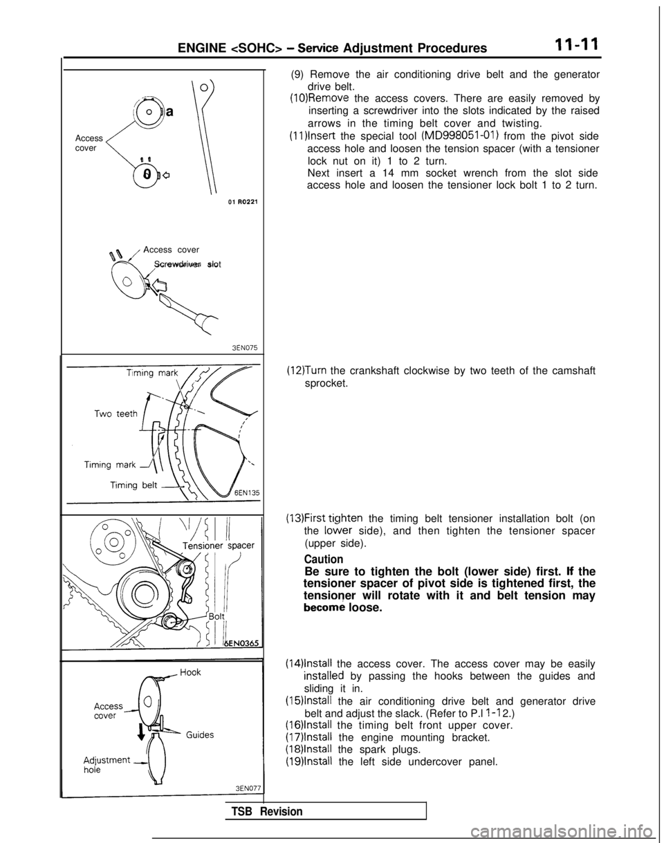
(9) Remove the air conditioning drive belt and the generator drive belt.
(10)Removle the access covers. There are easily removed by
inserting a screwdriver into the slots indicated by the raised
arrows in the timing belt cover and twisting. (1l)lnset-t
the special tool (MD998051-01)
from the pivot side
access hole and loosen the tension spacer (with a tensioner lock nut on it) 1 to 2 turn.
Next insert a 14 mm socket wrench from the slot side
access hole and loosen the tensioner lock bolt 1 to 2 turn.
(12)Turn the crankshaft clockwise by two teeth of the camshaft
sprocket.
(13)First ticjhten the timing belt tensioner installation bolt (on
the
lo&er side), and then tighten the tensioner spacer
(upper side).
Caution
Be sure to tighten the bolt (lower side) first. lf the
tensioner spacer of pivot side is tightened first, the
tensioner will rotate with it and belt tension may
becorn; loose.
(14)lnstall the access cover. The access cover may be easily
installeNd by passing the hooks between the guides and
sliding it in.
(15)lnstall the air conditioning drive belt and generator drive
belt and adjust the slack. (Refer to P.l
l-l 2.)
(16)lnstall the timing belt front upper cover.
(17)lnstall the engine mounting bracket.
(18)lnstall the spark plugs.
(19)lnstall the left side undercover panel.
TSB Revision