1989 MITSUBISHI GALANT warning
[x] Cancel search: warningPage 471 of 1273
ENGINE CONTROL - Service Adjustment Procedures13-329
SERVICE ADJUSTMENT PROCEDW,E,t&
ACCELERATOR CABLE INSPECTION AND
ADJUSTMENT
For models equipped with the auto-cruise control system, refer
to P. 13-398.
(1) Confirm there are no sharp bends in accelerator cable.
(2) On models with an SOHC engine, turn the ignition switch to the ON position (without starting the engine) and leave
in that condition for approximately 15 seconds.
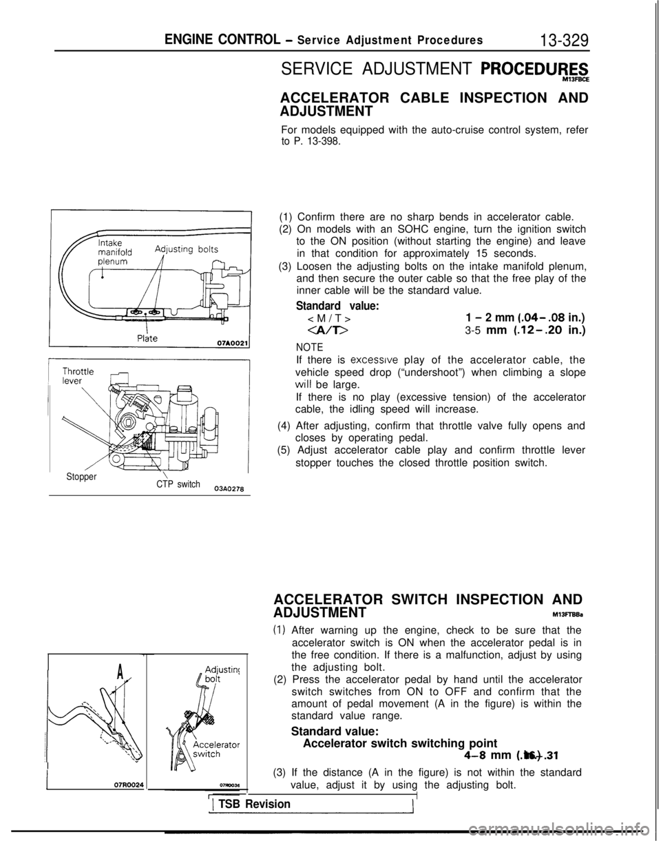
(3) Loosen the adjusting bolts on the intake manifold plenum, and then secure the outer cable so that the free play of theinner cable will be the standard value.
Standard value:
1 - 2 mm (.04- .08
in.)
-a/T>3-5 mm (.12-.20 in.)
NOTE
If there is excessrve play of the accelerator cable, the
vehicle speed drop (“undershoot”) when climbing a slope will
be large.
If there is no play (excessive tension) of the accelerator
cable, the idling speed will increase.
(4) After adjusting, confirm that throttle valve fully opens and closes by operating pedal.
(5) Adjust accelerator cable play and confirm throttle lever
stopper touches the closed throttle position switch.
Stopper\CTP switch03AO278
A
.-\\‘\.\ ‘\
!4
:l/.\\ \\‘\ I\*\\”
j 07R0024
ACCELERATOR SWITCH INSPECTION AND
ADJUSTMENTM13FTBBa
(1) After warning up the engine, check to be sure that theaccelerator switch is ON when the accelerator pedal is in
the free condition. If there is a malfunction, adjust by using
the adjusting bolt.
(2) Press the accelerator pedal by hand until the accelerator switch switches from ON to OFF and confirm that the
amount of pedal movement (A in the figure) is within the
standard value range.
Standard value: Accelerator switch switching point
4-8 mm (.16-.31 in.)
(3) If the distance (A in the figure) is not within the standard value, adjust it by using the adjusting bolt.
I1 TSB Revision
Page 950 of 1273
ACTIVE-ELECTRONIC CONTROL SUSPENSION - Troubleshooting 33B-11
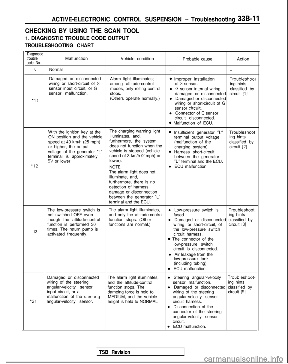
CHECKING BY USING THE SCAN TOOL
1. DIAGNOSTIC TROUBLE CODE OUTPUT
TROUBLESHOOTING CHART
DiagnostictroubleMalfunctionVehicle conditioncode No.Probable causeAction
0Normal---
Damaged or disconnected
Alarm light illuminates;0 Improper installation Troubleshoof
wiring or short-circuit of Gamong attitude-control of G sensor.
sensor input circuit, or Ging hints
modes, only rolling control
sensor malfunction. l
G sensor internal wiring
classified by
stops. damaged or disconnected. circuit
[I]
“11(Others operate normally.)l Damaged or disconnected
wiring or short-circuit of
G
sensor circurt.
l Connector of
G sensor
circuit disconnected.
0 Malfunction of ECU.
W
ith the ignition key at the
The charging warning light
ON position and the vehicle illuminates, and,
0 Insufficient generator “L”Troubleshoot
speed at 40 km/h (25 mph) furthermore, the system terminal output voltage
ing hints
or higher, the output does not function when the (malfunction of the
classified by
charging system). circuit
[2]
voltage of the generator ‘I”vehicle is stopped (vehicle0 Harness short-circuit
terminal is approximately speed of 3 km/h (2 mph) or
5V or lower
lower). between the generator“L” terminal and the ECU.“12
NOTEl ECU malfunction.
The alarm light does not illuminate, and,
furthermore, there is no
detection of harness
damage or disconnection
between the generator “L”
terminal and the ECU.
The low-pressure switch is The alarm light illuminates,
l Low-pressure switch is Troubleshoot
not switched OFF even and only the attitude-control
fused.
though the attitude-control ing hints
function stops. (Other l Damaged or disconnected classified by
function is performed 30 functions are normal.) circuit
131
13times. The return pump is wiring, or short-circuit, of
the low-pressure switch
activated frequently. circuit harness.
0 The connector of the
low-pressure switch
circuit is disconnected.
l Air leakage from the low-pressure tank
(including tubing).
l ECU malfunction.
“21
Damaged or disconnected The alarm light illuminates,l Steering angular-velocity Troubleshoot-
wiring of the steering and the attitude-control sensor malfunction.
angular-velocity sensor ing hints
function stops. The
input circuit, or a l Damaged or disconnected classified by
damping force is held to wiring of the steeringcircuit
191malfunction of the steenng
MEDIUM, and the vehicle
angular-velocity sensor. angular-velocity sensor
height is held to NORMAL circuit harness.
l Disconnection of the connector of the steering
angular-velocity sensor
circuit.
l ECU malfunction.
TSB Revision
Page 955 of 1273
33B-16 ACTIVE-ELECTRONIC CONTROL SUSPENSION - Troubleshooting
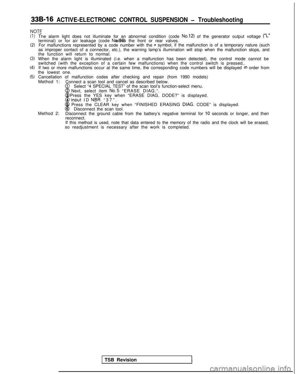
NOT’=
(1)
(2)
13)
(4)
(5)
‘T‘he alarm light does not illuminate for an abnormal condition (code No.12) of the generator output voltage (#,.terminal) or for air leakage (code No.56) within the front or rear valves.
For malfunctions represented by a code number with the* symbol, if the malfunction is of a temporary nature (such
as improper contact of a connector, etc.), the warning lamp’s illumi\
nation will stop when the malfunction stops, and
the function will return to normal.
When the alarm light is illuminated (i.e. when a malfunction has been d\
etected), the control mode cannot be switched (with the exception of a certain few malfunctions) when the c\
ontrol switch is pressed,.
If two or more malfunctions occur at the same time, the corresponding co\
de numbers will be displayed
In order from
the lowest one.
Cancellation of malfunction codes after checking and repair (from 1990 \
models)
Method 1: Connect a scan tool and cancel as described below.
1
w
Select “4 SPECIAL TEST” of the scan tool’s function-select menu\
.2 Next, select item No.5
“ERASE DIAG.“.
3 Press the YES key when “ERASE DIAG. DODE?” is displayed.
4
lnout ID NBR. “37”
.
8
5 Press the CLEAR key when “FINISHED ERASING DIAG. CODE” is displayed.6Disconnect the scan tool.
Method 2: Disconnect the ground cable from the battery’s negative terminal for \
10 seconds or longer, and then
reconnect.
If this method is used, note that data entered to the memory of the radi\
o and the clock will be erased,
so readjustment is necessary after the work is completed.
TSB Revision
1
Page 1122 of 1273
35-1
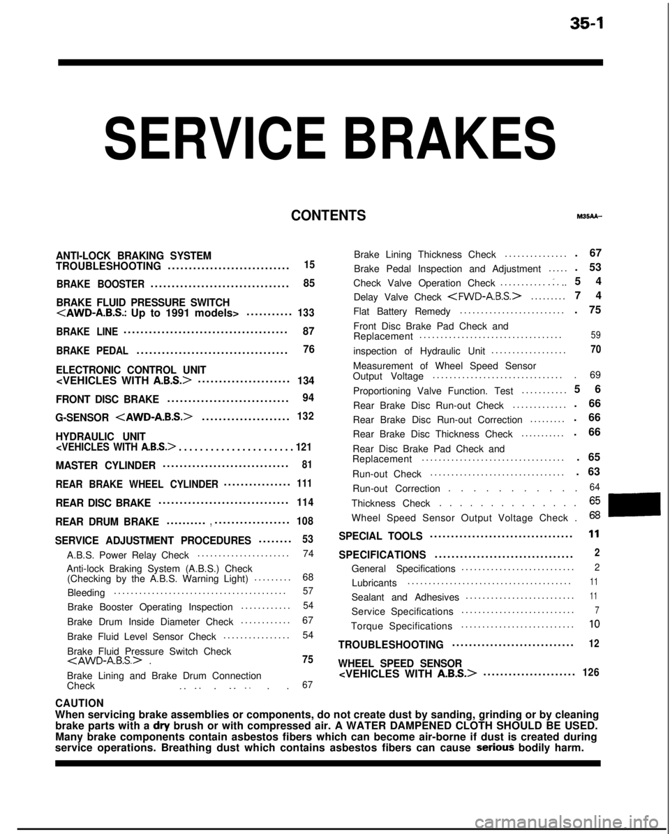
SERVICE BRAKES
CONTENTSM35AA-
ANTI-LOCK BRAKING SYSTEM
TROUBLESHOOTING............................
.
15
BRAKE BOOSTER
................................
.
85
BRAKE FLUID PRESSURE SWITCH
.
133
BRAKE LINE
......................................
.
87
BRAKE PEDAL...................................
.
76
ELECTRONIC CONTROL UNIT
......................134
FRONT DISC BRAKE
............................
.
94
G-SENSOR
.
132
HYDRAULIC UNIT
. . . . . . . . . . . . . . . . . . . . . . 121
MASTER CYLINDER.............................
.
81
REAR BRAKE WHEEL CYLINDER...............
.
111
REAR DISC BRAKE..............................
.
114
REAR DRUM BRAKE.........
.
,.................
.
108
SERVICE ADJUSTMENT PROCEDURES.......
.
53
A.B.S. Power Relay Check
.....................
.
74
Anti-lock Braking System (A.B.S.) Check (Checking by the A.B.S. Warning Light) .........
68
Bleeding .........................................
57
Brake Booster Operating Inspection
...........
.
54
Brake Drum Inside Diameter Check
...........
.
67
Brake Fluid Level Sensor Check ................
54
Brake Fluid Pressure Switch Check
Brake Lining and Brake Drum Connection
Check _. _. . _. _. . .67
Brake Lining Thickness Check ..............
.
Brake Pedal Inspection and Adjustment .....
Check Valve Operation Check ...........
.:...
Delay Valve Check
.
Flat Battery Remedy .........................
Front Disc Brake Pad Check and
Replacement ..................................
inspection of Hydraulic Unit ..................
Measurement of Wheel Speed Sensor
Output Voltage ...............................
Proportioning Valve Function. Test ...........
Rear Brake Disc Run-out Check .............
Rear Brake Disc Run-out Correction .........
Rear Brake Disc Thickness Check ...........
Rear Disc Brake Pad Check and
Replacement ..................................
Run-out Check ................................ . 67
. 53
54
74
. 75
59
70
. 69
5
6
. 66
. 66
. 66
. 65
. 63
Run-out Correction . . . . . . . . . . .
64
Thickness Check. . . . . . . . . . . . . .
Wheel Speed Sensor Output Voltage Check .
SPECIAL TOOLS.................................
.
11
SPECIFICATIONS................................
.
2
General Specifications
..........................
.
2
Lubricants
......................................
.
11
Sealant and Adhesives
.........................
.
11
Service Specifications
..........................
.
7
Torque Specifications
..........................
.
10
TROUBLESHOOTING............................
.
12
WHEEL SPEED SENSOR
.
126
CAUTION
When servicing brake assemblies or components, do not create dust by san\
ding, grinding or by cleaning
brake parts with a
dry brush or with compressed air. A WATER DAMPENED CLOTH SHOULD BE USED.
Many brake components contain asbestos fibers which can become air-borne\
if dust is created during
service operations. Breathing dust which contains asbestos fibers can ca\
use
seriouj bodily harm.
Page 1136 of 1273

SERVICE BRAKES - Anti-lock Braking System Troubleshooting35-15
ANTI-LOCK BRAKING SYSTEM
TROUBLESHOOTINGM35EElAE
PARTICULAR CHARACTERISTICS OF
THE ANTI-LOCK BRAKING SYSTEM
Models equipped with the anti-lock braking system
(A.B.S.) may exhibit one or more of the following
characteristics from time to time, but none of these
is abnormal.
(1)
(2)
A pulsing feeling in the brake pedal, or vibration
of the body or the steering wheel, when the
anti-lock braking system is activated by sudden
braking or by braking on a slippery road surface.
Actually, this phenomenon is an indication that
the anti-lock braking system is functioning nor-
mally.
When the vehicle speed reaches approximately
6 km/h (4 mph) after the engine is started and
the vehicle starts off (for the first time), awhining motor noise may be heard from the
engine compartment if the vehicle is traveling in
a quiet place. This noise is simply the result of a
self-check being made of the anti-lock braking
system operation.
TROUBLESHOOTING METHODS
Problems related to the anti-lock braking system
(A.B.S.) can be classified into two general categor-
ies: problems in the electrical system and those in
the hydraulic system. For problems in the electrical system, the on-board
diagnostic is built into the electronic control unit
(E.C.U.) causing the A.B.S. warning light to illuminate
as a warning to the driver. In this instance, checks
can be made by using the scan tool and oscillo-
scope.
Problems in the hydraulic system (poor braking,
etc.) can be located in the same way as for ordinary
brakes. There is, however, the necessity to check to
determine whether the problem is related to ordi-
nary brake components or to the components re-
lated to the A.B.S. To make this check, use the scan
tool.
HOW TO USE THE TROUBLESHOOTING
FLOW CHART
(1) Using the flow chart, check the ABS warning
light light-up sequence. Read the diagnostic
trouble codes and check the condition of bra-
king operation.
(2) Following the check chart listed in the remedy
column, perform the checks. There are [Expla- nation] and [Hint] in each check chart. Refer to
them when troubleshooting.
NOTE
ECU: Electronic control unit
HU:Hydraulic unit
TSB Revision
Page 1137 of 1273
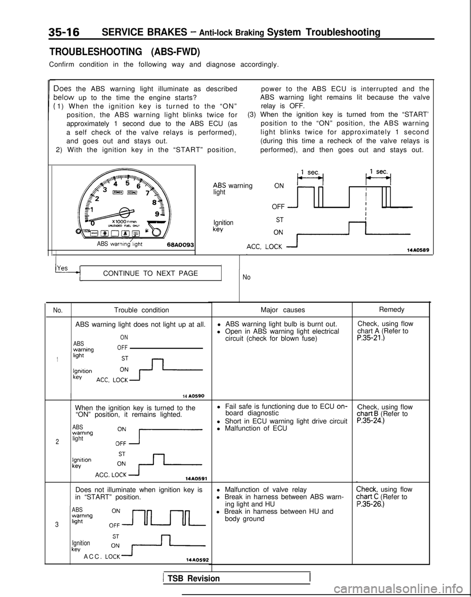
35-16SERVICE BRAKES - Anti-lock Braking System Troubleshooting
TROUBLESHOOTING (ABS-FWD)
Confirm condition in the following way and diagnose accordingly.
Ioes the ABS warning light illuminate as describedpower to the ABS ECU is interrupted and the
lelow up to the time the engine starts?ABS warning light remains lit because the valve
1) When the ignition key is turned to the “ON” relay is OFF.
position, the ABS warning light blinks twice for (3) When the ignition key is turned from the “START’
approximately 1 second due to the ABS ECU (as position to the “ON” position, the ABS warning
a self check of the valve relays is performed), light blinks twice for approximately 1 second
and goes out and stays out. (during this time a recheck of the valve relays is
2) With the ignition key in the “START” position, performed), and then goes out and stays out.
ABS warning
,,lseq (se+
lightII
OFF -I
Ignitionkey
ABS warnmg/;,ght68A009314A0589
YAS rICONTINUE TO NEXT PAGENo
No.
Trouble condition
ABS warning light does not light up at all.
ABSwarnina
ON
OFF
1light -
lgnltionkey
I14 A0590
When the ignition key is turned to the l Fail safe is functioning due to ECU on-
“ON” position, it remains lighted. board diagnostic
ABSwarning
2lightOZ7
l Short in ECU warning light drive circuit
l Malfunction of ECU
lgnitlonkev
ACC. LOi+14A0591
Does not illuminate when ignition key is
in “START” position.
ABSwarning
3light
Ignition
key ACC. LO:+14AO592
Major causes
l ABS warning light bulb is burnt out.
l Open in ABS warning light electrical circuit (check for blown fuse)
l Malfunction of valve relay
l Break in harness between ABS warn- ing light and HU
l Break in harness between HU and body ground Remedy
Check, using flow
chart A (Refer to
P.35-21.)
Check, using flowchart B (Refer toP.35-24.)
Check, using flow:hart C (Refer to ‘.35-26.)
1 TSB Revision
Page 1138 of 1273
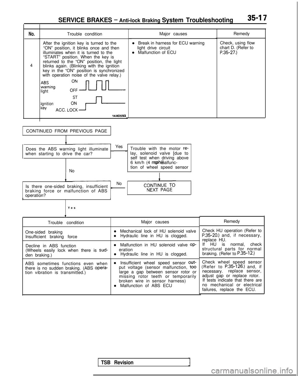
SERVICE BRAKES - Anti-lock Braking System Troubleshooting35-I 7
No.
4
Trouble condition
After the ignition key is turned to the “ON” position, it blinks once and then
illuminates when it is turned to the “START” position. When the key is
returned to the “ON” position, the light
blinks again. (Blinking with the ignition
key in the “ON” position is synchronized
with operation noise of the valve relay.)
ABSwarning
ighto:=
gnition:eyACC. LCFY-
14AO593
Major causes
l Break in harness for ECU warning light drive circuit
l Malfunction of ECU
CONTINUED FROM PREVIOUS PAGE
Does the ABS warning light illuminate
_Yes Trouble with the motor re-
when starting to drive the car?
c lay, solenoid valve [due to self test when driving above
6 km/h (4 mph)] or malfunc-
Notion of wheel speed sensor
I
Is there one-sided braking, insufficientNo
L
braking force or malfunction of ABS
operation?
I
Yes
t
Trouble condition
One-sided braking Insufficient braking force
Decline in ABS function
I
Major causes
l Mechanical lock of HU solenoid valve
l Hydraulic line in HU is clogged.
l Malfunction in HU solenoid valve
op-
(Wheels easily lock when there is sud-
eration
den braking.) l Hydraulic line in HU is clogged.
ABS sometimes functions even when l Insufficient wheel speed sensor out-
there is no sudden braking. (ABS opera-
put voltage (sensor malfunction,
to0
tion vibration is transmitted.)
large a gap between sensor rotor or
missing rotor teeth or temporarily
broken wire in sensor harness)
l Malfunction of ABS ECU Remedy
Check, using flow
chart D. (Refer to
P.35-27.)
Remedy
Check HU operation (Refer to
P.35-20.) and, if necessary,
replace HU. If HU is normal, check
structural parts for normal
braking. (Refer to
P.35-12.)
Check wheel speed sensor
(Refer to P.35-126.) and, if
necessary. replace sensor,
adjust gap or replace rotor. If tests indicate that there are
no mechanical or electrical
failures, replace the ECU.
TSB Revision
Page 1140 of 1273
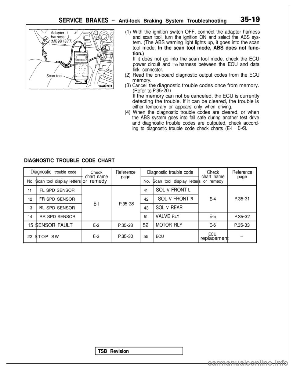
SERVICE BRAKES - Anti-lock Braking System Troubleshooting35-19
(1) With the ignition switch OFF, connect the adapter harness
and scan tool, turn the ignition ON and select the ABS sys-
tem. (The ABS warning light lights up, it goes into the scan
tool mode.
In the scan tool mode, ABS does not func-
tion.)
If it does not go into the scan tool mode, check the ECU
power circuit and
the harness between the ECU and data
link connector.
(2) Read the on-board diagnostic output codes from the ECU
(3) ?a\?zl’ythe diagnostic trouble codes once from memory.
(Refer to P.35-20.)
If the memory can not be canceled, the ECU is currently
detecting the trouble. If it can be cleared, the trouble is
either temporary or appears only when driving.
(4) When the diagnostic trouble codes are cleared, or when
the ABS system goes into fail safe during another test drive
and diagnostic trouble codes are outputed, check accord-
ing to diagnostic trouble code check charts (E-l -E-6).
DIAGNOSTIC TROUBLE CODE CHART
Diagnostic trouble code CheckReferenceDiagnostic trouble codeCheckReference
chart name
pawchart namepawNo. Scan tool display letters or remedy No. Scan tool display letters or remedy
11FL SPD SENSOR41SOL V FRONT L
12FR SPD SENSOR42SOL V FRONT RE-4P.35-31
E-lP.35-2813RL SPD SENSOR
43SOL V REAR
14RR SPD SENSOR51VALVE RLYE-5P.35-32
15 SENSOR FAULTE-2P.35-28 52MOTOR RLYE-6P.35-33
22 STOP SWE-3P.35-30 55ECU ECUreplacement -
TSB Revision