1989 MITSUBISHI GALANT charging
[x] Cancel search: chargingPage 587 of 1273
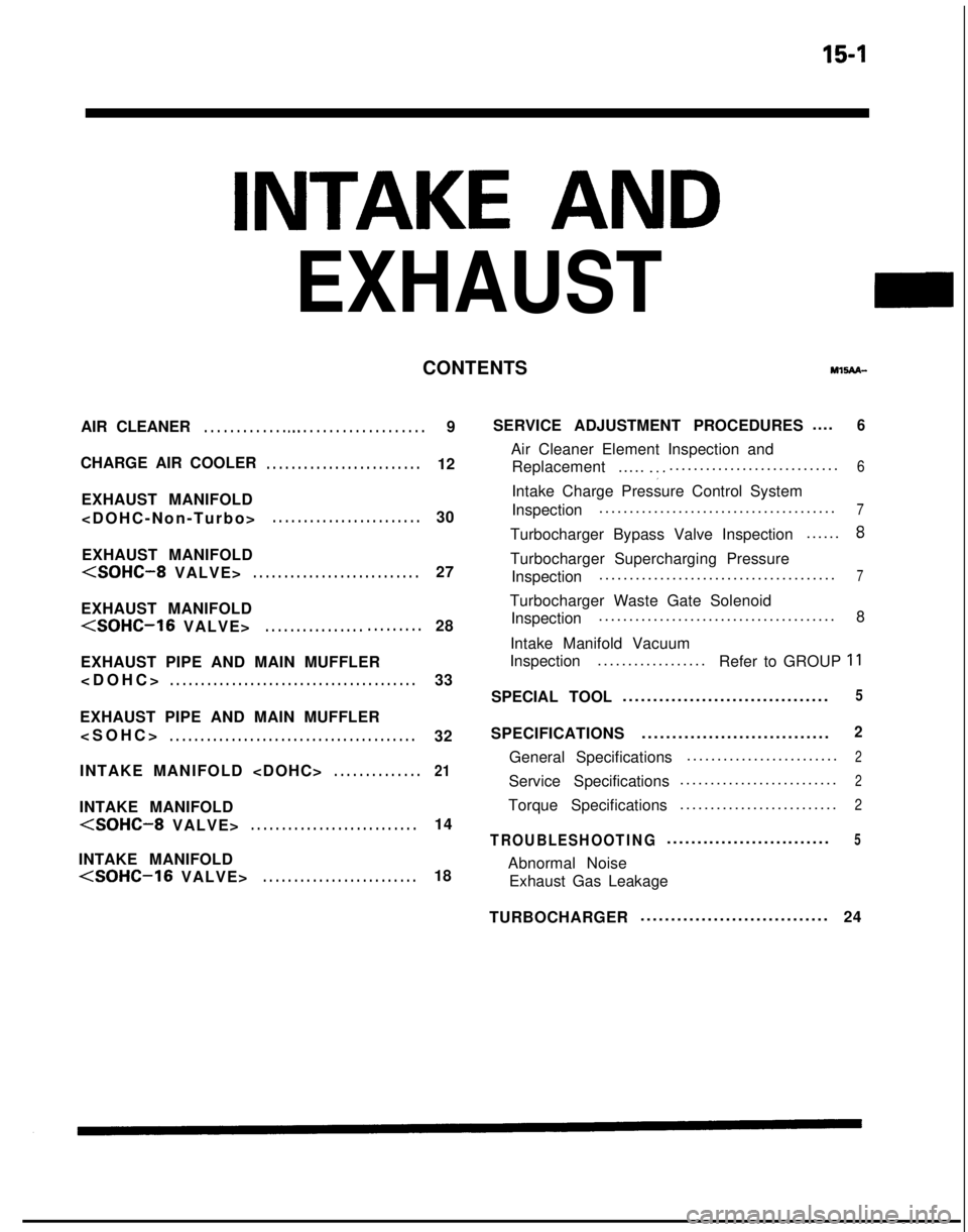
15-1
INTAKE AND
EXHAUST
CONTENTSMl!iAn-
AIR CLEANER. . . . . . . . . . . . . a.. . . . . . . . . . . . . . . . . . . .9
CHARGE AIR COOLER
. . . . . . . . . . . . . . . . . . . . . . . . .12
EXHAUST MANIFOLD
. . . . . . . . . . . . . . . . . . . . . . . .30
EXHAUST MANIFOLD
EXHAUST MANIFOLD
EXHAUST PIPE AND MAIN MUFFLER
. . . . . . . . . . . . . . . . . . . . . . . . . . . . . . . . . . . . \
. . . .33
EXHAUST PIPE AND MAIN MUFFLER
. . . . . . . . . . . . . . . . . . . . . . . . . . . . . . . . . . . . \
. . . .32
INTAKE MANIFOLD
. . . . . . . . . . . . . .21
INTAKE MANIFOLD
INTAKE MANIFOLD
(SOHC-16 VALVE>. . . . . . . . . . . . . . . . . . . . . . . . .18 SERVICE ADJUSTMENT PROCEDURES
....
6
Air Cleaner Element Inspection and
Replacement .....
.:............................
.
6
Intake Charge Pressure Control System
Inspection
......................................
.
7
Turbocharger Bypass Valve Inspection
.....
.
8
Turbocharger Supercharging Pressure
Inspection ......................................
.
7
Turbocharger Waste Gate Solenoid
Inspection ......................................
.
8
Intake Manifold Vacuum
Inspection ..................
Refer to GROUP
11
SPECIAL TOOL .................................
.
5
SPECIFICATIONS
..............................
.
2
General Specifications
........................
.
2
Service Specifications
.........................
.
2
Torque Specifications
.........................
.
2
TROUBLESHOOTING...........................5
Abnormal Noise
Exhaust Gas Leakage
TURBOCHARGER ..............................
.
24
Page 588 of 1273
15-2INTAKE AND EXHAUST - Specifications
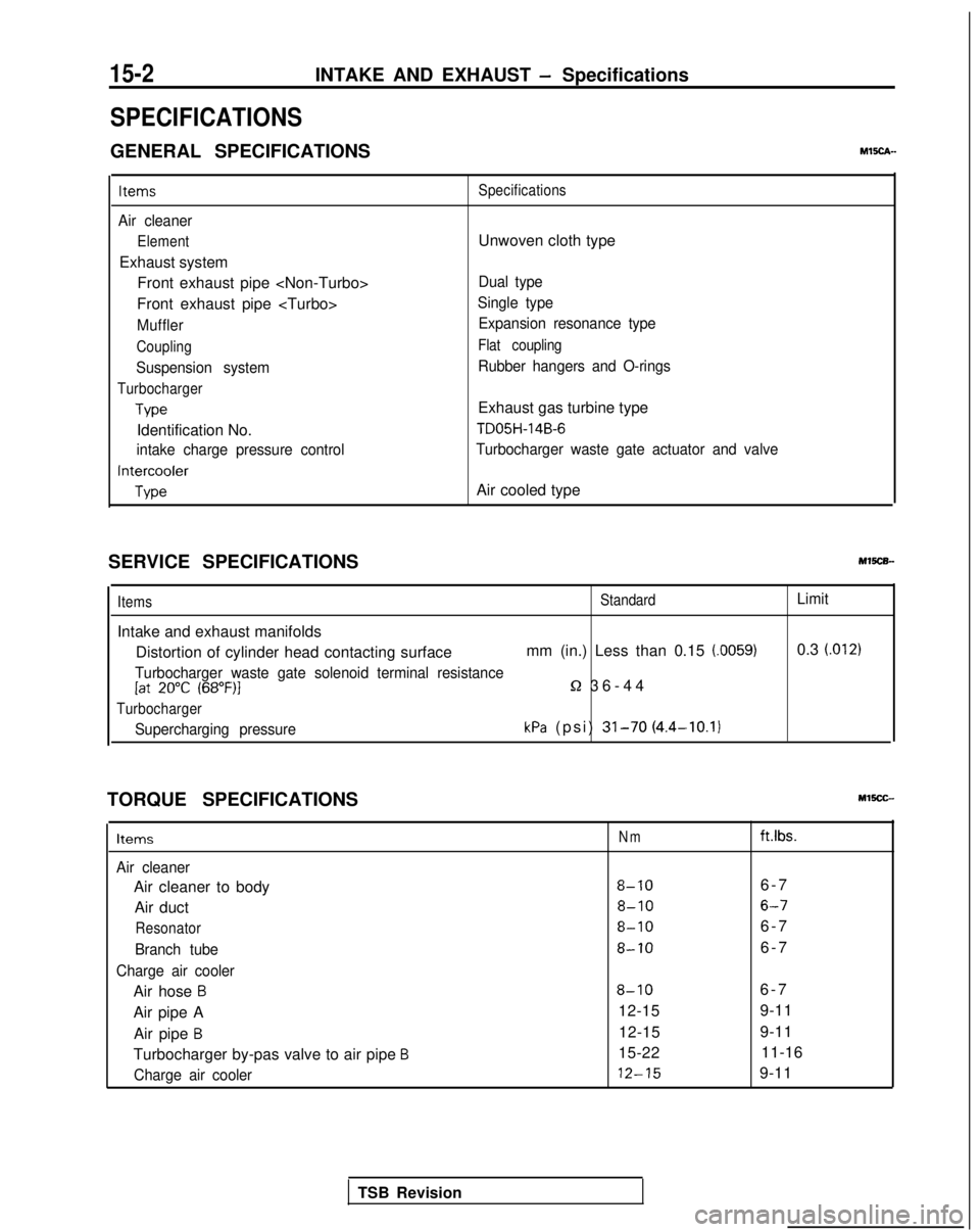
SPECIFICATIONS
GENERAL SPECIFICATIONSMEch-
Items
Air cleaner
Element
Exhaust systemFront exhaust pipe
Front exhaust pipe
Muffler
Coupling
Suspension system
Turbocharger
Type
Identification No.
intake charge pressure control
Intercooler
Type Specifications
Unwoven cloth type
Dual type
Single type Expansion resonance type
Flat coupling
Rubber hangers and O-rings
Exhaust gas turbine type
TD05H-14B-6
Turbocharger waste gate actuator and valve
Air cooled type
SERVICE SPECIFICATIONS
Items
Intake and exhaust manifolds
StandardLimit
Distortion of cylinder head contacting surface mm (in.) Less than 0.15 (0059)0.3 (.012)
Turbocharger waste gate solenoid terminal resistance[at 20°C (68”F)l5-2 36-4
4
Turbocharger
Supercharging pressurekPa (psi) 31-70 (4.4-10.1)
TORQUE SPECIFICATIONS
Items
Air cleaner
Air cleaner to body
Air duct
Resonator
Branch tube
Charge air cooler
Air hose B
Air pipe A Air pipe
B
Turbocharger by-pas valve to air pipe B
Charge air cooler
Nmft.lbs.
8-106-
7
8-106-7
8-106-
7
8-106-
7
8-106-
7
12-15 9-11
12-15 9-11
15-22 11-16 12-15
9-11
TSB Revision
Page 593 of 1273
INTAKE AND EXHAUST - Service Adjustment Procedures15-7
Turbocharger waste
gate actuator
05A0150
OSAOlSl
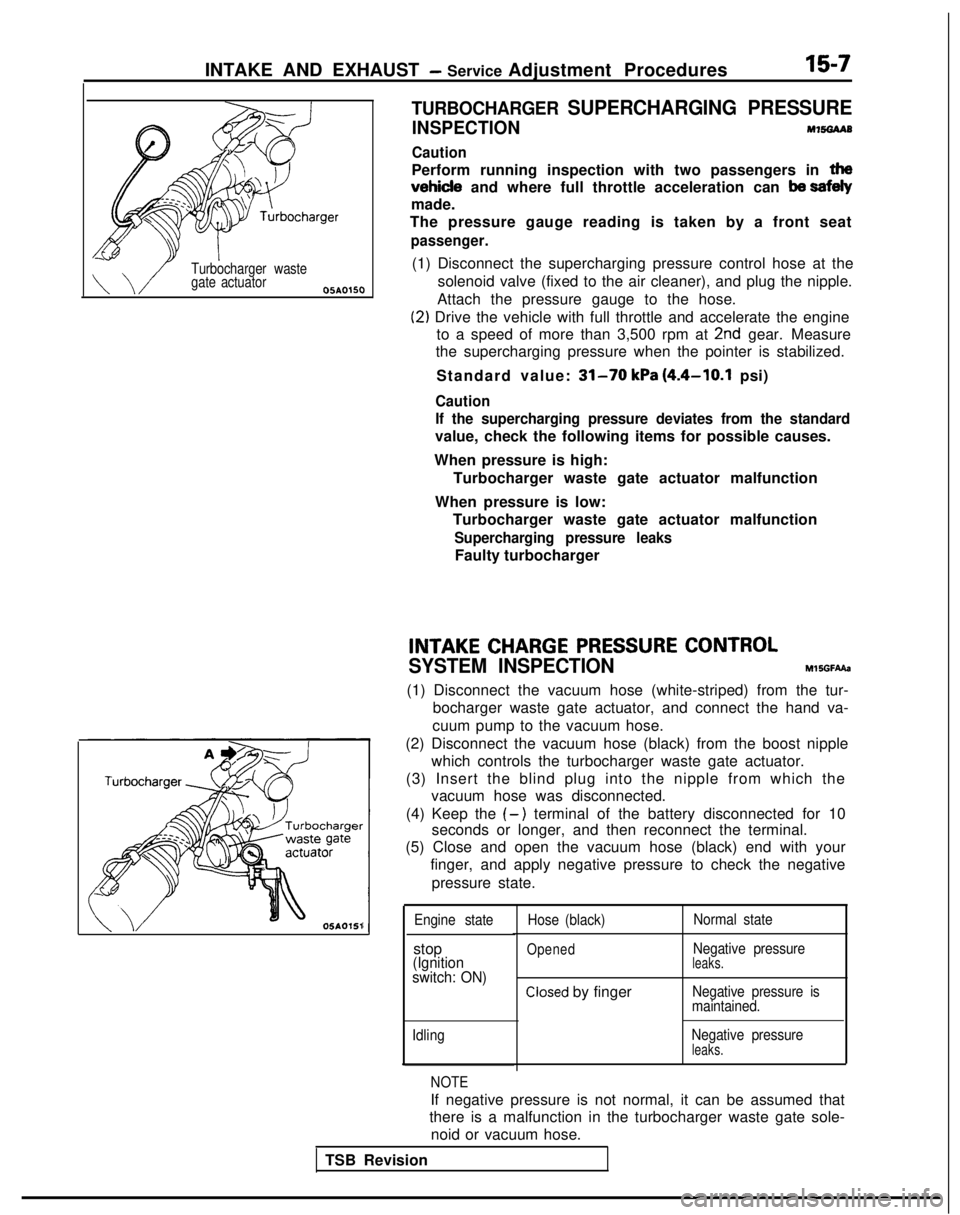
TURBOCHARGER SUPERCHARGING PRESSURE
INSPECTIONM7!%3AAB
Caution
Perform running inspection with two passengers in tha
vehicle and where full throttle acceleration can ba sefely
made.
The pressure gauge reading is taken by a front seat
passenger.
(1) Disconnect the supercharging pressure control hose at the
solenoid valve (fixed to the air cleaner), and plug the nipple.
Attach the pressure gauge to the hose.
(2) Drive the vehicle with full throttle and accelerate the engine to a speed of more than 3,500 rpm at
2nd gear. Measure
the supercharging pressure when the pointer is stabilized.
Standard value:
31-70 kPa (4.4-10.1 psi)
Caution
If the supercharging pressure deviates from the standard
value, check the following items for possible causes.
When pressure is high: Turbocharger waste gate actuator malfunction
When pressure is low: Turbocharger waste gate actuator malfunction
Supercharging pressure leaks
Faulty turbocharger
INTAKECHARGEPRESSURECONTROL
SYSTEM INSPECTION
MlSGFAAa
(1) Disconnect the vacuum hose (white-striped) from the tur- bocharger waste gate actuator, and connect the hand va-
cuum pump to the vacuum hose.
(2) Disconnect the vacuum hose (black) from the boost nipple which controls the turbocharger waste gate actuator.
(3) Insert the blind plug into the nipple from which the vacuum hose was disconnected.
(4) Keep the
(-) terminal of the battery disconnected for 10
seconds or longer, and then reconnect the terminal.
(5) Close and open the vacuum hose (black) end with your
finger, and apply negative pressure to check the negative
pressure state.
Engine state
stop(Ignition
switch: ON)
Idling Hose (black)
Opened
Normal state
Negative pressure
leaks.
Closed by fingerNegative pressure is
maintained.
Negative pressure
leaks.
NOTE
If negative pressure is not normal, it can be assumed that
there is a malfunction in the turbocharger waste gate sole-
noid or vacuum hose.
TSB Revision
Page 950 of 1273
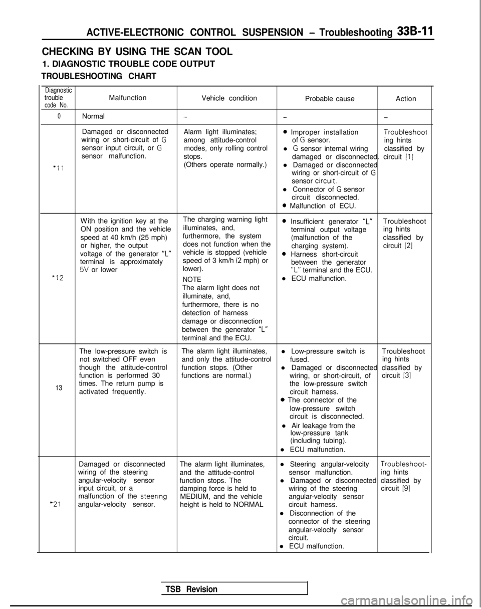
ACTIVE-ELECTRONIC CONTROL SUSPENSION - Troubleshooting 33B-11
CHECKING BY USING THE SCAN TOOL
1. DIAGNOSTIC TROUBLE CODE OUTPUT
TROUBLESHOOTING CHART
DiagnostictroubleMalfunctionVehicle conditioncode No.Probable causeAction
0Normal---
Damaged or disconnected
Alarm light illuminates;0 Improper installation Troubleshoof
wiring or short-circuit of Gamong attitude-control of G sensor.
sensor input circuit, or Ging hints
modes, only rolling control
sensor malfunction. l
G sensor internal wiring
classified by
stops. damaged or disconnected. circuit
[I]
“11(Others operate normally.)l Damaged or disconnected
wiring or short-circuit of
G
sensor circurt.
l Connector of
G sensor
circuit disconnected.
0 Malfunction of ECU.
W
ith the ignition key at the
The charging warning light
ON position and the vehicle illuminates, and,
0 Insufficient generator “L”Troubleshoot
speed at 40 km/h (25 mph) furthermore, the system terminal output voltage
ing hints
or higher, the output does not function when the (malfunction of the
classified by
charging system). circuit
[2]
voltage of the generator ‘I”vehicle is stopped (vehicle0 Harness short-circuit
terminal is approximately speed of 3 km/h (2 mph) or
5V or lower
lower). between the generator“L” terminal and the ECU.“12
NOTEl ECU malfunction.
The alarm light does not illuminate, and,
furthermore, there is no
detection of harness
damage or disconnection
between the generator “L”
terminal and the ECU.
The low-pressure switch is The alarm light illuminates,
l Low-pressure switch is Troubleshoot
not switched OFF even and only the attitude-control
fused.
though the attitude-control ing hints
function stops. (Other l Damaged or disconnected classified by
function is performed 30 functions are normal.) circuit
131
13times. The return pump is wiring, or short-circuit, of
the low-pressure switch
activated frequently. circuit harness.
0 The connector of the
low-pressure switch
circuit is disconnected.
l Air leakage from the low-pressure tank
(including tubing).
l ECU malfunction.
“21
Damaged or disconnected The alarm light illuminates,l Steering angular-velocity Troubleshoot-
wiring of the steering and the attitude-control sensor malfunction.
angular-velocity sensor ing hints
function stops. The
input circuit, or a l Damaged or disconnected classified by
damping force is held to wiring of the steeringcircuit
191malfunction of the steenng
MEDIUM, and the vehicle
angular-velocity sensor. angular-velocity sensor
height is held to NORMAL circuit harness.
l Disconnection of the connector of the steering
angular-velocity sensor
circuit.
l ECU malfunction.
TSB Revision
Page 1263 of 1273
2ALPHABETICAL INDEX
BRAKE LINING ThicknessCheck
.., ..,............
Drum, Rear, Maintenanc
e
BRAKE LINING AND BRAKE DRUM, Connection Check..
BRAKE PAD
Drsc, Front, Check and Replacemen
t
Disc, Rear, Check and Replacement BRAKEPEDAL..
BRAKE PEDAL, Inspection and Adjustment
BUMPER..... 35-67-l
00-44-l
35-67-l
35-59-l
35-65-l
35-76-l
35-53-l
51-7-I
C
CABLEAccelerator, Inspection and Adjustment
Accelerator, Inspection and Adjustment
High
Tensron, Spark Test
.
16-42-11Parking Brake................................
.
36-5-l
Spark
Plug, Tes
t
........................
16-42-11Speedometer, Replacement ...............
.
23-93-l
Speedometer, Replacement
.
22-19-I
Speedometer, Replacement
.
22-5-l
CAMSHAFTDOH
C
...................
1 l-68-lSOHC.................................
.
11-19-I
CAMSHAFT OIL SEALS
DOHC
...................................
.
11-68-I
SOHC........................................
.
11-19-I
CAMSHAFT POSITION SENSOR
On-vehrcle Inspection
..................
.
13-277-l
On-vehicle Inspection
.
13-69-l
On-vehicle Inspection
.
13-165-I
CANISTER,
Evaporatjve Emission.................
.
17-21-l
CATALYTIC CONVERTER............................
.
17-24-l
CENTERMEMBER...................
.
....... 32-8-l
CENTRAL DOOR LOCKING SYSTEM..................
.
42-101-I
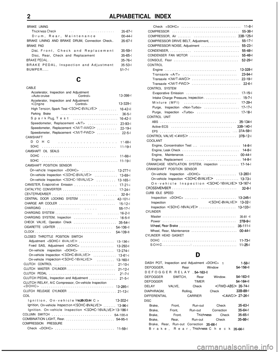
CHARGE AIR COOLER...............................
.
15-l
2-l
CHARGING..................
.
..... 55-17-I
CHARGING SYSTEM....................
.
...........
16-2-11CHARGING SYSTEM, Inspection.......................
.
16-5-11CHECK VALVE, Operation Check......................
.
35-54-l
CIGARETTE LIGHTER..........................
.
54-106-11
CLOCK........................................
.
54-109-11CLOSED THROTTLE POSITION SWITCHAdjustment
.................. 13-136-I
Frxed SAS, Adjustment
..................
.
13-250-I
On-vehicle inspection
On-vehicle Inspection
.
13-61-I
On-vehicle Inspection
. 13-160-I
CLUTCH CONTROL.................................
.
21-10-I
CLUTCH MASTER CYLINDER.........................
.
21-12-l
CLUTCH PEDAL.....................................
.
21-7-l
CLUTCH PEDAL, Inspection and Adjustment ................
21-5-1CLUTCH RELAY, A/C Compressor, On-vehicle Inspection
....................................... 13-285-l
CLUTCH RELEASE CYLINDER.........................
21-13-lCOIL
Ignition, On-vehicle
Inspectron
Ignition, On-vehicle
InspectIon
. 13-96-l
Ignition. On-vehicle Inspection
COLUMN SWITCH............................
.
54-100-11COMBINATION LIGHT, Rear.
.........................
.
54-95-11COMPRESSION PRESSURE
Check
...............................
.
1
i-59-1Check
..................................
11-8-l
COMPRESSOR...................................
.
55-38-l
COMPRESSOR, Air.......
.
........................ 338-125-I
COMPRESSOR DRIVE BELT, Adjustment, ................. 55-17-l
COMPRESSOR NOISE, Adjustment ...................... 55-23-l
CONDENSER, ............ .......................... 55-48-l
CONDENSER FAN MOTOR...........................
.
55-48-l
CONSOLE, Floor....................................
.
52-29-l
CONTROL
Engine
........................................
.
13-328-l
Transaxle ............................... 23-94-l
Transaxle
.
22-19-I
Transaxle
.
22-6-l
CONTROL SYSTEM
Evaporative Emission
.............................
.
17-15-l
Intake Charge Pressure, Inspection.
....................
15-7-lMixture (MFI
)
.............................. 17-29-l
Purge, Inspection
Purge, Inspection
CONTROL UNIT
ABS
........................................
.
35-134-l
Active-ECS ................................... 338-140-I
EPS.....................................
.
...37A-59-lCONTROL VALVE <4WS>..........................
.
378-12-I
COOLANT
Engine, Concentration Test ..........................
14-8-lEngine, Leak Check ................................
.
14-8-l
Engine, Maintenance. ............................ 00-44-I
Engine, Replacement ...........
................... 14-8-lCRANKCASE VENTILATION SYSTEM, inspection..........
.
17-14-l
CRANKSHAFT POSITION SENSOR
On-vehicle Inspection
..................
.
13-280-I
On-vehicle Inspection
.
13-73-l
On-vehicle Inspection
CROSSMEMBER....................................
.
32-8-l
CURB IDLE SPEED
Inspection
.......
.
.................... 13-245-l
Inspection
Inspection
.
13-133-l
CYLINDER
Master
.........................................
.
35-81 -IPower
.........................................
.
378-9-I
Wheel,RearBrake...............................
. 35-111-l
Wheel, Rear, Maintenance .......................... 00-44-I
CYLINDER HEAD GASKET
DOHC
.......................................
.
11-73-l
SOHC.................: ......................... 11-25-l
D
DASH POT, Inspection and Adjustment
1 l-58-lDEFOGGER, Rear Window 64-156-11
DEFOGGER RELA
Y
.54-163-11DEFOGGER SWITCH, Rear Window. 54-163-11
DEFOGGER TIMER 54-164-11
DELAY VALVE, Check
35-74-l
DIAPHRAGM, Rolling, Check 33B-89-l
DIFFERENTIAL CARRIER
DISC
Brake, Front, Run-out Check
35-63-l
Brake, Front, Run-out Correction 35-64-l
Brake, Front.
Thichness Check 35-65-l
Brake, Rear, Run-out Check 35-66-l
Brake, Rear, Run-out Correction 35-66-l
Brake, Rear,
Thichness Chec
k
35-66-l
Page 1270 of 1273
ALPHABETICAL INDEX
EGR
k
37A-19-I
Evaporative Emission Purge
17-21 -IEvaporative Emission Purge, On-vehicle Inspection
Evaporative Emission Purge, On-vehicle Inspection
Evaporative Emission Purge, On-vehicle Inspection
Fuel Pressure
13-307-I
Turbocharger Waste Gate, Inspectron
15-8-l
Turbocharger Waste Gate, On-vehicle Inspection
00-40-I
16-42-11
16-42-11
54-151-I
35-126-l
35-69-l
23-93-l
22-19-l
22-5-l
SPARK PLUG
Maintenanc
e
........
Test .........................
SPARK PLUG CABLE, Test........
.
SPEAKER.......................
.
SPEED SENSOR
Wheel
.
Wheel, Output Voltage Measurement
SPEEDOMETER CABLE
Replacement ..........
.
Replacement
.
Replacement
.
STABILIZER BAR
Active-ECS
.........
.
Front
Suspensron...........
.
Rear Suspension
.
STARTER MOTOR..................
.
STARTING SYSTEM................
.
STEERING GEAR BOX, Power.........
.
STEERING LINKAGE SEALS, Maintenance
STEERING SHAFT.................
.
STEERING WHEEL..............
.
STEERING WHEEL
AngleCheck.....................
. 37A-15-l
Centering ...................... 37A-16-l
Free Play Check. ............... 37A-15-l
Return to Center Check ............. 37A-19-l
STOP LIGHT, High Mounted ...........
54-96-l
I
STOPPER, Roll. Engine
................
. 32-6-i
STRUT
Active-ECS
338-97-I
.......
Front Suspension. ........................... 33A-6-l
...
SUNROOFBody
..........................
.
.......... 42-116-l
Fit Adjustment ................................ 42-53-l
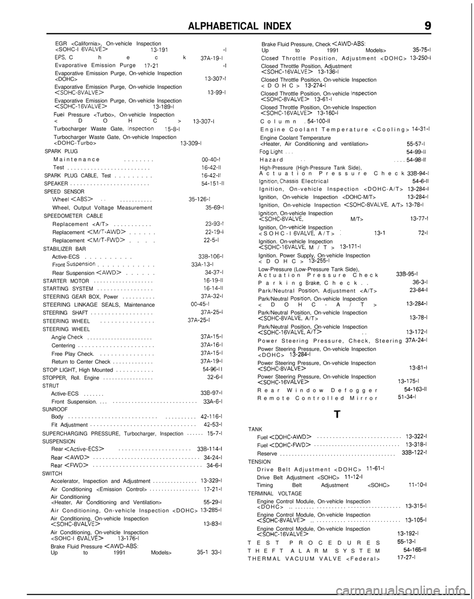
SUPERCHARGING PRESSURE, Turbocharger, Inspection.....
.
15-7-l
SUSPENSIONRear
.
33B-114-l
Rear
.
34-24-l
Rear
.
34-6-i
SWITCHAccelerator, Inspection and Adjustment
..............
.
13-329-l
Air Conditioning
33A-13-l
34-37-l
16-19-1116-14-I
37A-32-l
00-45-I
37A-25-1
37A-25-I
Air Conditioning
Air Conditioning, On-vehicle Inspection
Air Conditioning, On-vehicle Inspection
Air Conditioning, On-vehicle Inspection
13-176-l
Brake Fluid Pressure
Brake Fluid Pressure, Check
Closed Throttle Position, Adjustment
13-250-l
Closed Throttle Position, Adjustment
Closed Throttle Position, On-vehicle Inspection
Closed Throttle Position, On-vehicle Inspection
13-61-l
Closed Throttle Position, On-vehicle Inspection
Column
.54-100-11Engine Coolant Temperature
Engine Coolant Temperature
FogLight...
Hazar
d
., .._.
High-Pressure (High-Pressure Tank Side),Actuation Pressure Chec
k
Ignrtion, Chasscs Electrical
Ignition, On-vehicle Inspection
Ignition, On-vehicle Inspection
Ignition, On-vehicle Inspection
54-99-11
54-98-11
33B-94-l
54-6-11
13-284-i
13-284-l
13-78-l
Ignitron. On-vehicle Inspection
Ignition, On-vehicle
Inspection
: 13-I 72-l
Ignition. On-vehicle Inspection
Ignition. Power Supply, On-vehicle Inspection
Low-Pressure (Low-Pressure Tank Side),
Actuation Pressure Check
Parking
Brake. Check.
.
Park/Neutral
Posrtion, Adjustment
Park/Neutral
Posrtion, On-vehicle Inspection
Park/Neutral Position, On-vehicle Inspection
36-3-l
23-84-l
13-284-I
13-78-l
Park/Neutral Position, On-vehicle Inspection
Power Steering Pressure, Check, Steering 37A-24-l
Power Steering Pressure, On-vehicle Inspection
Power Steering Pressure, On-vehicle Inspection
Rear Window Defogge
r
Remote Controlled Mirror 13-81-l
13-175-l
54-163-11
51-34-l
T
TANK
Fuel
.
13-322-l
Fuel
.
13-318-I
Reserve ....................................... 338-122-I
TENSIONDrive Belt Adjustment
>
11-61-1
Drive Belt Adjustment
11-12-I
Timing Belt Adjustment
TERMINAL VOLTAGE
Engine Control Module, On-vehicle Inspection
.................. 13-315-l
.. ....... ..........
Engine Control Module, On-vehicle Inspection
.
13-l 05-i..
.........
.
Engine Control Module, On-vehicle Inspection
TEST PROCEDURE
S
THEFT ALARM SYSTEM THERMAL VACUUM VALVE
55-13-l
54-165-11
17-27-l
Page 1271 of 1273
