1989 MITSUBISHI GALANT sensor
[x] Cancel search: sensorPage 8 of 1273
00-6GENERAL - How to Use This Manual
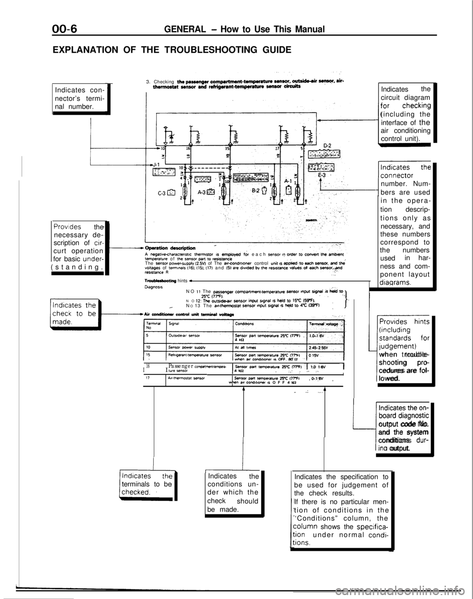
EXPLANATION OF THE TROUBLESHOOTING GUIDEIndicates con-
nector’s termi-
nal number. 3. Checking
the pasmngw compartment-twnpwatu* UnSO!. ~ F, ah-thermo8tat sensor and refdgwant-tempnaturs sensor ufalitsIndicates
the
circuit diagram
(including the interface of the
air conditioning
control unit).
number. Num-
bers are used temperawe
of
the Sensor pm
to resistanceeach sensor t? order to convest lb+ amben
The sense, power-supply l2.W of The atrcOnd,f,oner control unit s aD&d~to each SmSOt snd lhevoltages of te,mmaIs 116). (151. (17) and (51 are
dwded by the reslstme va!ueS.of each ““Freelstance R..
TmuMnhooting
hints *Dtagnoss
in the opera
-
tion descrip-
tions only as necessary, and
these numbers
correspond to
the numbers
used in har-
ness and com-
ponent layout diagrams.Provides
the
necessary de-
scription of
cir-
curt operation
for basic under-
(standing.
NO
1, The passenger cPrrlpmme”l-lemperatu4
-r tnput sigrml is
hid toZ’C (77-F).,, “”NO 1’2 The ou~sde.ar sensor
inpu
srgnal IS held to WC (5IpF).._N
O 13 The air#t,?,mpSf~ SenSO, VlPut SlgMl 6 t+ 10 4% G33-F):I-Airwndtlimluconhdunittwmirutwtmge
~~
I16I lYle *“MIPassenger com,wnme”t-tawa.1 sensor Parr lem,mat”r~ 25-c OFFI 7 to WV1,‘W. _: ,. L. .LI17A~r.,hermos,at seworsensor
Pm
remoeraure 2% 177% WM”
m cQndlt*Ow IS OFF 1 Lo, o-‘l,W
,
terminals to be 4
_
.: ._. 4
-hiIndicates
the
conditions un-
der which the
check should
be made. Provides hints
(including
standards for
I-- judgement)
when trouble-
shooting
pro-
cedures are fol-
lowed.
Indicates the on-
board diagnostic
L:
output code No.
and the system
conditions
dur-
ina output.
Indicates the specification to
be used for judgement of
the check results.
If there is no particular men-
tion of conditions in th
e
‘Conditions” column, the column
shows the
specifica-:ionunder normal condi-
:ions.
Page 41 of 1273
GENERAL - Scheduled Maintenance Table/Maintenance Service00-39
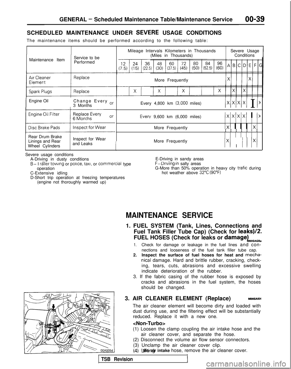
SCHEDULED MAINTENANCE UNDER SEVEiRE USAGE CONDITIONS
The maintenance items should be performed according to the following tab\
le:
Maintenance Item Service to be
Performed
IEngine Oil Change Every or
3 Months
(:z:.:a::I
Rear Drum Brake
Linings and Rear
Wheel Cylinders Inspect for Wear
and Leaks
1
Mileage Intervals Kilometers in Thousands (Miles in Thousands) Severe Usage
Conditions
More Frequently
Every 4,800 km
(3,000 miles)/xlxlx/xI I I1 Every
9,600 km (6,000 miles)
IxIxlxIxI I I>(
More Frequently1x1 I I I 1x1I I I I I I I
More Frequently
Ix1 I I I lx/
Severe usage conditions A-Driving in dusty conditions
- -B- I railer
towing or police.
taxi,
or commercial
type
operation
C-Extensive idling
D-Short trip operation at freezing temperatures (engine not thoroughly warmed up) E-Driving in sandy areas- -..F-Dnvlng In salty areas
G-More than 50% operation in heavy city trafic during
hot weather above 32°C (90°F)
MAINTENANCE SERVICE
1. FUEL SYSTEM (Tank, Lines, Connections and
Fuel Tank Filler Tube Cap) (Check for leaks)/2.
FUEL HOSES (Check for leaks or
damagekOOSnOB.
1.Check for damage or leakage in the fuel lines and con-
nections and looseness of the fuel tank filler tube cap.
2. Inspect the surface of fuel hoses for heat and mecha-
nicall damage. Hard and brittle rubber, cracking, check-
ing, tears, cuts, abrasions and excessive swelling
indicate deterioration of the rubber.
3. If the fabric casing of the rubber hose is exposed by cracks and abrasions in the fuel system, the hoses
should be changed.
3. AIR CLEANER ELEMENT (Replace)
MMlSAKH
The air cleaner element will become dirty and loaded with dust during use, and the filtering effect will be substantiallyreduced. Replace it with a new one.
(1) Loosen the clamp coupling the air intake hose and the air cleaner cover, and separate the hose.
(2) Disconnect the volume air flow sensor connectors.
(3) Unclamp the air cleaner cover clip.
(4) Lifting the air intake hose, remove the air cleaner cover.
TSB Revision1
Page 42 of 1273
00-40GENERAL- Maintenance Service
Caution
The air cleaner cover should be removed carefully,
because it includes the volume air flow sensor.
/
(5) Remove the air cleaner element.(6) Set a new air cleaner element and install the air cleaner cover.
I hose,I
Plug gapgauge
Measurementrection01
If
0110182
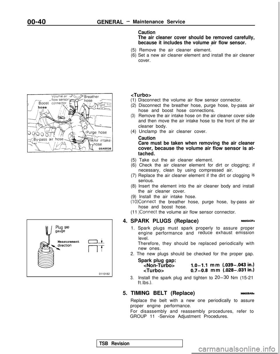
(1) Disconnect the volume air flow sensor connector.
(2) Disconnect the breather hose, purge hose, by-pass air hose and boost hose connections.
(3)Remove the air intake hose on the air cleaner cover side
and then move the air intake hose to the front of the air
cleaner body.
(4) Unclamp the air cleaner cover.
Caution
Care must be taken when removing the air cleaner
cover, because the volume air flow sensor is at-
tached.
(5) Take out the air cleaner element.
(6) Check the air cleaner element for dirt or clogging; if necessary, clean by using compressed air.
(7) Replace the air cleaner element if the dirt or clogging
is
serious.
(8) Insert the element into the air cleaner body and install the air cleaner cover.
(9) Install the air intake hose.
(10)Connect the breather hose, purge hose, by-pass air
hose and boost hose.
(11
)Connect the volume air flow sensor connector.
4. SPARK PLUGS (Replace)
h%OSAOFa
1. Spark plugs must spark properly to assure proper engine performance and reduce exhaust emission
level.
Therefore, they should be replaced periodically with
new ones.
2. The new plugs should be checked for the proper gap.
Spark plug gap:
mm (.039-.043
in.)
0.7-0.8 mm (.028-.031 in.)
3.Install the spark plug and tighten to 20-30 Nm (15-21
ftlbs.).
5. TIMING BELT (Replace)moossAsa
Replace the belt with a new one periodically to assure
proper engine performance.
For disassembly and reassembly procedures, refer to
GROUP 11 -Service Adjustment Procedures.
TSB Revision
Page 48 of 1273
00-46GENERAL - Table of Main Sealants and Adhesives
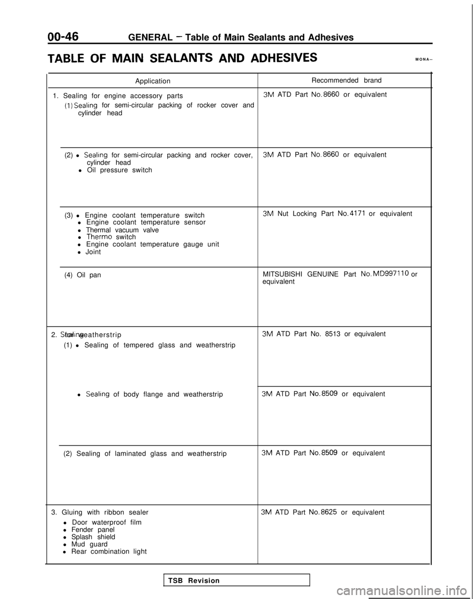
TABLEOF MAINSEALANTS
AND
ADHESIVES
MONA--
Application Recommended brand
1. Sealing for engine accessory parts 3M
ATD Part No.8660
or equivalent
(1) Sealing
for semi-circular packing of rocker cover and
cylinder head
(2) l
Sealrng for semi-circular packing and rocker cover, 3M
ATD Part No.8660
or equivalent
cylinder head
l Oil pressure switch
(3) l Engine coolant temperature switch l Engine coolant temperature sensor
l Thermal vacuum valvel Therm0
switch
l Engine coolant temperature gauge unit
l Joint 3M
Nut Locking Part
No.4171 or equivalent
(4) Oil pan MITSUBISHI GENUINE Part No.MD997110
or
equivalent
2. Sealing for weatherstrip
(1) l Sealing of tempered glass and weatherstrip 3M
ATD Part No. 8513 or equivalent
l Sealing
of body flange and weatherstrip 3M
ATD Part No.8509
or equivalent
(2) Sealing of laminated glass and weatherstrip 3M
ATD Part No.8509
or equivalent
3. Gluing with ribbon sealer l Door waterproof film
l Fender panel
l Splash shield
l Mud guard 3M
ATD Part No.8625
or equivalent
l Rear combination light TSB Revision
Page 65 of 1273
ENGINE
35-4
5
25-33 35-45 Nm
25-33
ft.lbs.
24
35-45 N
m
25-33
ft.lbs.
23-2
7
250166309
I23
:l;nbs.
50-65 Nm
36-47 ft.lbs.
dv--iu wm: ’22-29 ft.lbs. \ d.(,(I3L i‘9
50-65 Nm*Cb36-47 ft.lbs.* -
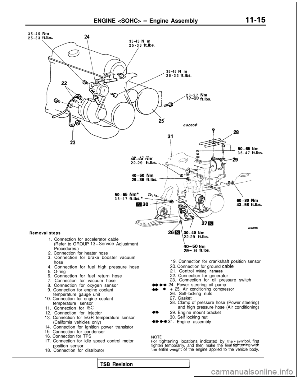
Removal steps
1. Connection for accelerator cable(Refer to GROUP
13-Service Adjustment
Procedures.)
2. Connection for heater hose
3. Connection for brake booster vacuum
hose
4. Connection for fuel high pressure hose 5. O-ring
6. Connection for fuel return hose
7. Connection for vacuum hose
8. Connection for oxygen sensor
9. Connection for engine coolant temperature gauge unit
10. Connection for engine coolant
temperature sensor
11. Connection for
ISC12. Connection for injector13. Connection for EGR temperature sensor (California vehicles only)
14. Connection for ignition power transistor
15. Connection for condenser
16. Connection for TPS
17. Connection for idle speed control motor
position sensor
18. Connection for distributor
30-40 Nm
\22-29 ft.lbs.
bO-50 Nm29- 36 ft.lbs.
19. Connection for crankshaft position sensor
20. Connection for ground cable
21. Control wiring harness
22. Connection for generator
23. Connection for oil pressure switch
dae I)* 24. Power steering oil pump
28. Clamp of pressure hose (Power steering) and high pressure hose (Air conditioning)
29. Engine mount bracket
30. Self locking nut
,** *+ 31. Engine assembly
IdOTEf-or tightening locations indicated by the * symbol. firsttighten temporarily, and then make the final tightenrng wrth?he entire werght of the engine applied to the vehicle body.
TSB Revision1
Page 67 of 1273
ENGINE
ENGINE ASSEMBLY
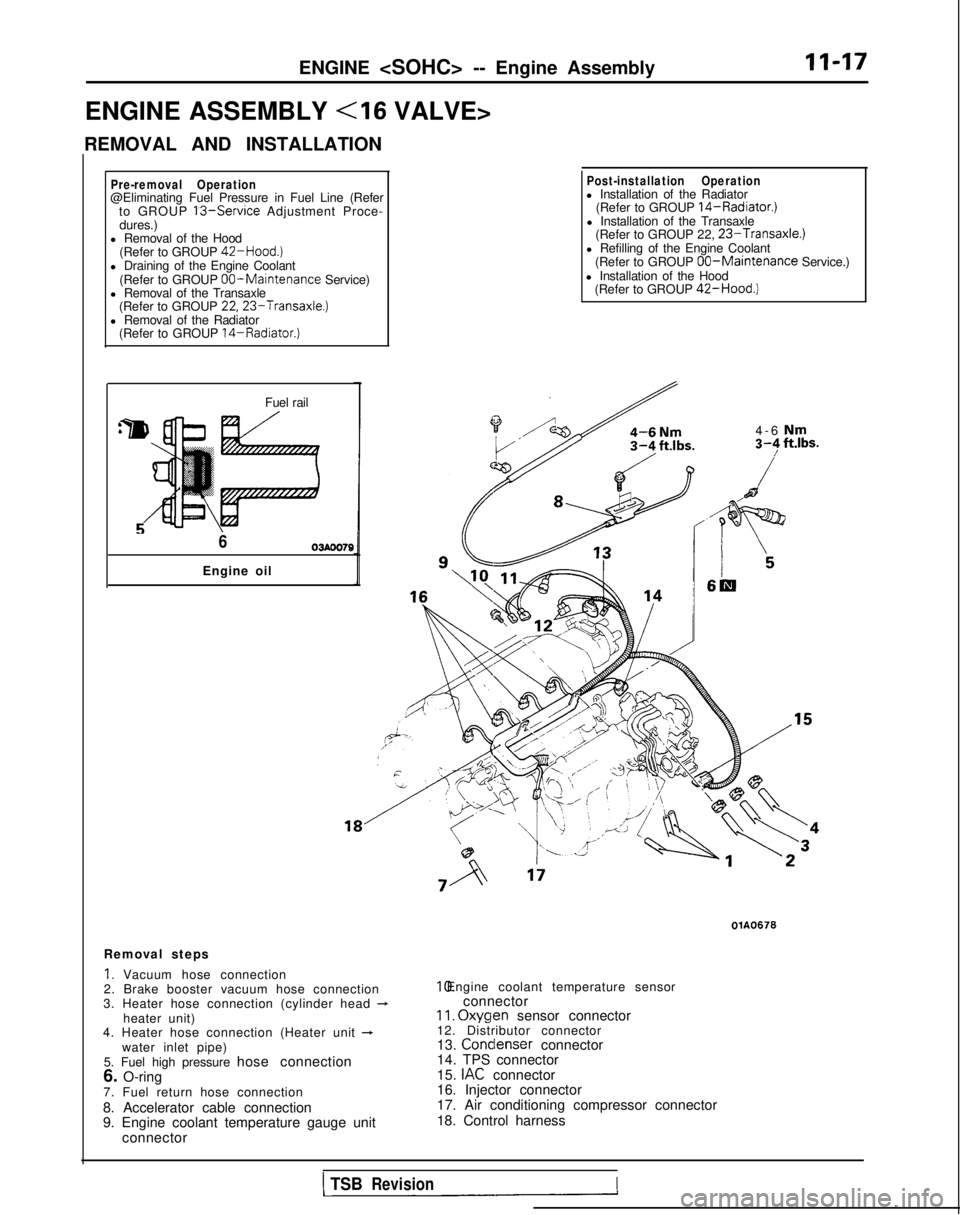
REMOVAL AND INSTALLATION
II-17
Pre-removal Operation@Eliminating Fuel Pressure in Fuel Line (Refer to GROUP 13-Service Adjustment Proce-
dures.)
l Removal of the Hood
(Refer to GROUP
42-Hood.)l Draining of the Engine Coolant
(Refer to GROUP 00-Maintenance Service)
l Removal of the Transaxle (Refer to GROUP
22,23-Transaxle.)l Removal of the Radiator(Refer to GROUP 14-Radiator.)
Fuel rail
603AOO70
Engine oil
Post-installation Operationl Installation of the Radiator (Refer to GROUP 14-Radiator.)l Installation of the Transaxle(Refer to GROUP 22, 23-Transaxle.)l Refilling of the Engine Coolant
(Refer to GROUP 00-Maintenance Service.)
l Installation of the Hood (Refer to GROUP
42-Hood.)
4-6 Nm3-F ft.lbs.
I6m
Removal steps
1. Vacuum hose connection
2. Brake booster vacuum hose connection
3. Heater hose connection (cylinder head
-heater unit)
4. Heater hose connection (Heater unit +water inlet pipe)
5. Fuel high pressure hose connection
6. O-ring
7. Fuel return hose connection
8. Accelerator cable connection
9. Engine coolant temperature gauge unit connector
OlA0676 10. Engine coolant temperature sensor
connector
II. Oxyqen
sensor connector
12. Distributor connector
13. Condenser
connector
14. TPS connector
15.
IAC connector
16. Injector connector
17. Air conditioning compressor connector
18. Control harness
1 TSBRevisionI
Page 76 of 1273
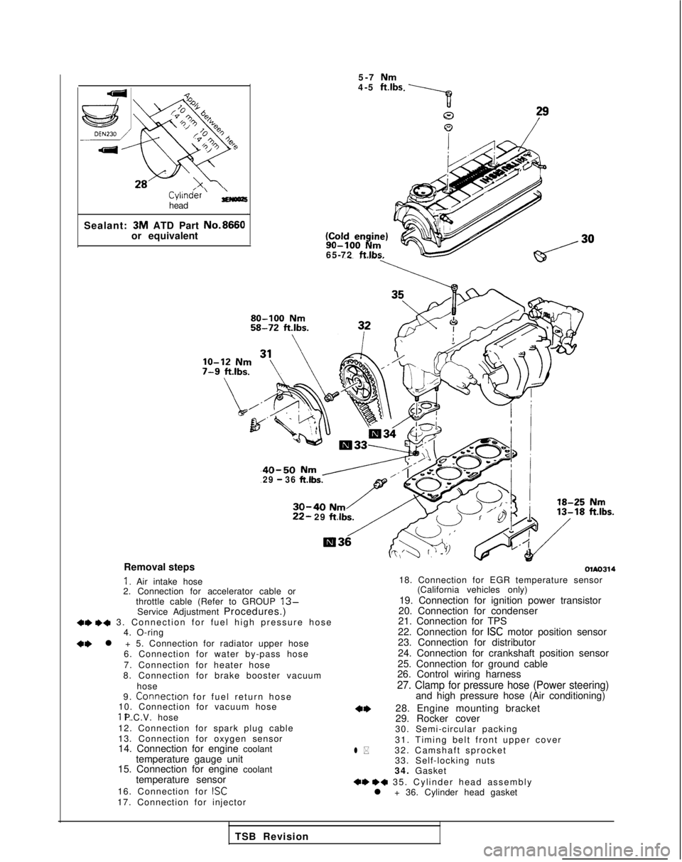
Cyl1n&r’ ;;(oozhead
Sealant: 3M
ATD Part No.8660
or equivalent 5-7
Nm4-5 ft.lbs 90-100
Nm65-72 ftlbs.
40-50 Nm /29 - 36 ft.lbs.
30-40 Nm22- 29
ftlbs.
Removal steps
I. Air intake hose
2. Connection for accelerator cable or
throttle cable (Refer to GROUP
13-Service Adjustment Procedures.)+e +a 3. Connection for fuel high pressure hos
e
4. O-ring
+e l + 5. Connection for radiator upper hose
6. Connection for water by-pass hose
7. Connection for heater hose
8. Connection for brake booster vacuum
hose
9.
Connectron for fuel return hos
e
10. Connection for vacuum hose 11. P.C.V. hose
12. Connection for spark plug cable
13. Connection for oxygen sensor
14. Connection for engine coolant temperature gauge unit
15. Connection for engine coolant
temperature sensor
16. Connection for
ISC17. Connection for injector
olAo314
l *
18. Connection for EGR temperature sensor (California vehicles only)
19. Connection for ignition power transistor
20. Connection for condenser
21. Connection for TPS
22. Connection for
ISC motor position sensor
23. Connection for distributor
24. Connection for crankshaft position sensor
25. Connection for ground cable
26. Control wiring harness
27. Clamp for pressure hose (Power steering)and high pressure hose (Air conditioning)
28. Engine mounting bracket
29. Rocker cover
30. Semi-circular packing
31. Timing belt front upper cover
32. Camshaft sprocket 33. Self-locking nuts
34. Gasket
+e ++ 35. Cylinder head assembl
y
l + 36. Cylinder head gasket
TSB Revision
Page 80 of 1273
II-30ENGINE
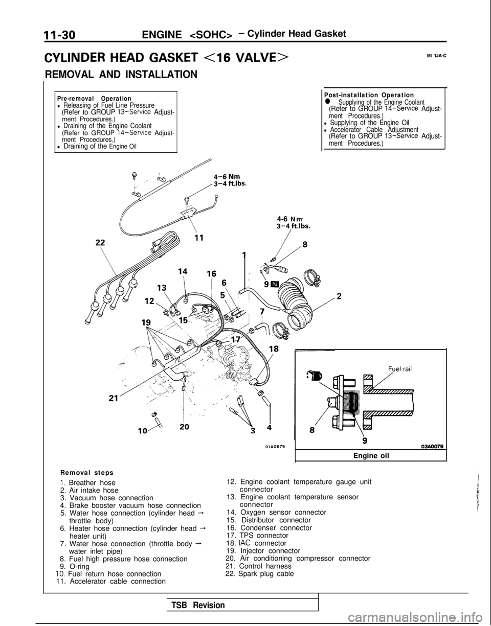
CYLINDER HEAD GASKET
REMOVAL AND INSTALLATION
Ml IJA-C
Pre-removal Operationl Releasing of Fuel Line Pressure(Refer to GROUP 13-Service Adjust-ment Procedures.)l Draining of the Engine Coolant(Refer to GROUP 14-Service Adjust-
ment Procedures.)
l Draining of the Engine Oil
il4-6 Nm
Post-installation Operationl Supplying of the Engine Coolant(Refer to GROUP 14-Service Adjust-ment Procedures.)l Supplying of the Engine Oill Accelerator Cable Adjustment(Refer to GROUP 13-Service Adjust-ment Procedures.)
Removal steps
I. Breather hose
2. Air intake hose
3. Vacuum hose connection
4. Brake booster vacuum hose connection 5. Water hose connection (cylinder head
-throttle body)
6. Heater hose connection (cylinder head --Lheater unit)
7. Water hose connection (throttle body -water inlet pipe)
8. Fuel high pressure hose connection
9. O-ring
10. Fuel return hose connection
11. Accelerator cable connection
2
9.
Engine oil
12. Engine coolant temperature gauge unit connector
13. Engine coolant temperature sensor connector
14. Oxygen sensor connector
15. Distributor connector
16. Condenser connector
17. TPS connector
18.
IAC connector
19. Injector connector
20. Air conditioning compressor connector
21. Control harness
22. Spark plug cable
TSB Revision