Page 159 of 1273

FUEL SYSTEM - Troubleshooting 13-17
\ I\-\\\\\\6FUO807
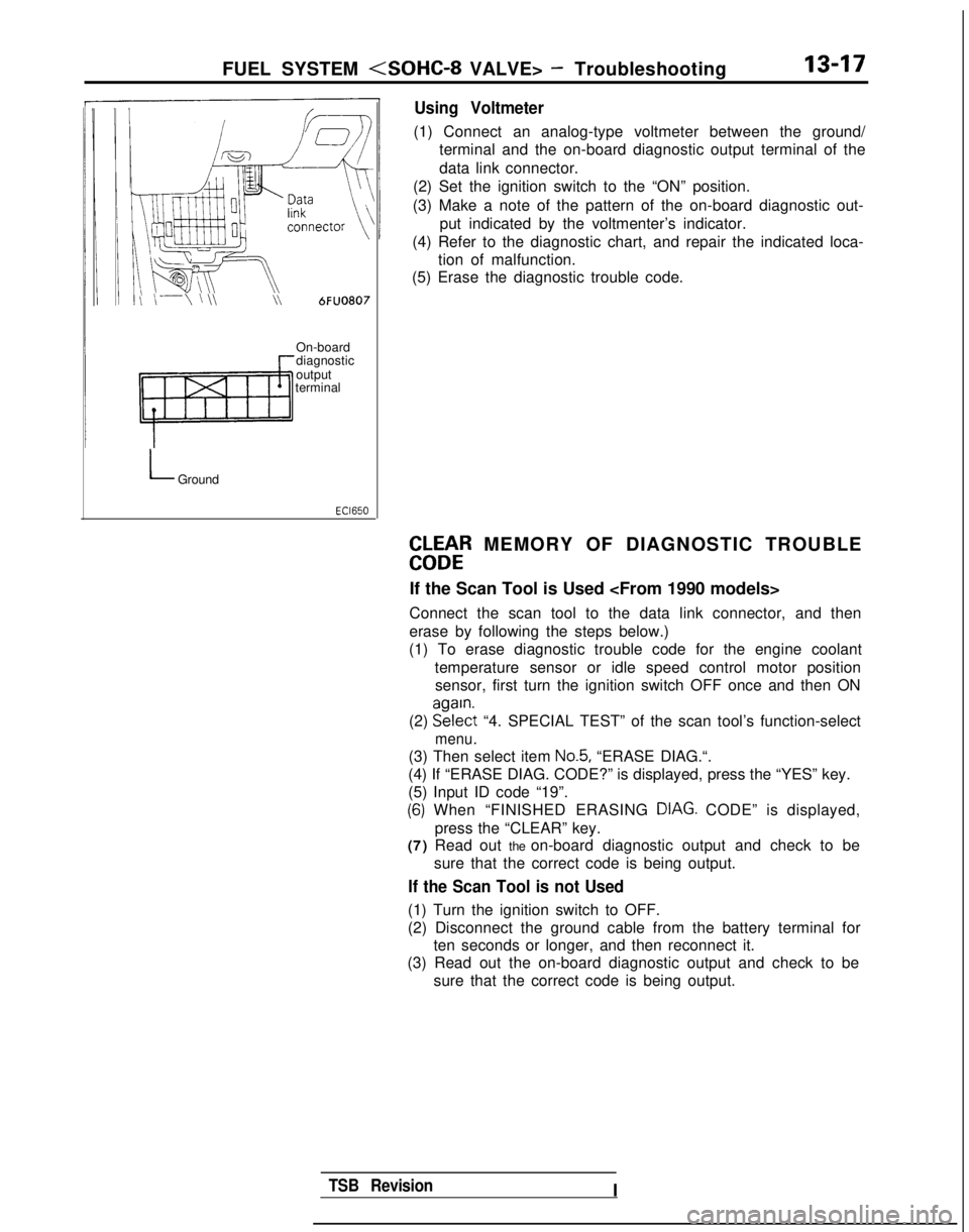
Using Voltmeter
(1) Connect an analog-type voltmeter between the ground/
terminal and the on-board diagnostic output terminal of the
data link connector.
(2) Set the ignition switch to the “ON” position.
(3) Make a note of the pattern of the on-board diagnostic out- put indicated by the voltmenter’s indicator.
(4) Refer to the diagnostic chart, and repair the indicated loca- tion of malfunction.
(5) Erase the diagnostic trouble code.
On-board
diagnostic
output
terminal
LGround
EbLbtR MEMORY OF DIAGNOSTIC TROUBLE
If the Scan Tool is Used
Connect the scan tool to the data link connector, and then
erase by following the steps below.)
(1) To erase diagnostic trouble code for the engine coolant
temperature sensor or idle speed control motor positionsensor, first turn the ignition switch OFF once and then ON
(2) EE?$t
“4. SPECIAL TEST” of the scan tool’s function-select
menu.
(3) Then select item No.5, “ERASE DIAG.“.
(4) If “ERASE DIAG. CODE?” is displayed, press the “YES” k\
ey.
(5) Input ID code “19”.
(6) When “FINISHED ERASING DIAG. CODE” is displayed,> Ipress the “CLEAR” key.
(7) Read out the on-board diagnostic output and check to be
sure that the correct code is being output.
If the Scan Tool is not Used
(1) Turn the ignition switch to OFF.
(2) Disconnect the ground cable from the battery terminal forten seconds or longer, and then reconnect it.
(3) Read out the on-board diagnostic output and check to be
sure that the correct code is being output.
TSB RevisionI
Page 164 of 1273
13-22
FUEL SYSTEM - Troubleshooting
CIRCUIT DIAGRAM (CONTINUED)
< 1989 models>
IGNITIONSWITCHlIGl)#OF?OWERMFIRELAYIGNIlTRANf
;ROLKUN1
am\lR Fl.tlW i=XNSOR
A-57
II Il-
EF g?JEi _______ JLllOI:02&j12_1---& im
Y-+-I
k$$
Yh
I5VI I 5Y
syv s_v-e-*-e
-
“,
*-r
-5. IIII 5.5
c
L
III I
III1II --I-
-
I
II,---
1’ 8Iis%%
Gi3mv1 a+2 pg3 $14I
?Ic
IDLE SPEEDCONTROL MOTORPOSITJON SENSOR
A-53 12El(VEHICLES FOR94CALIFORNIA)
B-02 B @
KX35-AC-HO525A-NY
B-04 m
1 TSB Revision1I
Page 165 of 1273
FUEL SYSTEM - Troubleshooting13-23
--
r-B-20 I
LXYG~!tEN6OR 1
’I
W!E~W~,F;~R
-2 EVAPORATIVE ! ““L;,$ m&S-ON
h SOLENOID,\,C” 1 PI FR
*q
1:
2_1 El ,
Lk.i,i iiI
NJECTOi- 11
B-12 =
m
2
7'
2
A-56
IIQI2
/A T//
cpII
Ii
ime Ii i aI
%
i
‘OR
7VE
ICI A
I
“d
OT
4
-1 ;;I
I
5v
r5
s.- -
I
1
4J
POWERPRESSU
' OXYGEN SENSOR'(VEHICLES FOR
FEDE;zd
C-18 FRONT SIDE
DATA LINKCONNECTOR
4
IENG)
(DATA)
c-40
plqismq
C-38
7
F
J/B
cp4
", H
I e
Ell94
TSB RevisionI
Page 169 of 1273
FUEL SYSTEM (SOHC-8 VALVE> - Troubleshooting13-27
INJECTOR&INJECTOR&INJECTOR&NJEC
--
!-B-20 -7
!OXYGE!!ENSOR I'(VEHICLES FORCALIFORNIA)
5v
-w-Qz-I-
-
^
_____---______-_- ---____--&vs-- -__---- T18
I1
>
,..
-----.2
15
12
I
----.58
8
I
1
IDLE SPEEDDATA LINKCONTROL MOTORCONNECTOR
59
cl-11
I
2
1
m
II
!II II1
ib -
I
' OXYGEN SENSOR'(VEHICLES FOR
FEDE89":;
i 63 i
TSB RevisionI
Page 172 of 1273
13-30FUEL SYSTEM - Troubleshooting
CIRCUIT DIAGRAM (CONTINUED)
<1991,1992 models>
IGNITIONSWITCH(IG1)IGNITION POWERTRANSISTOR
FROL
91
\lxI
z;.
F
R
VOLUME AIR FLOW SENSORs
LYAYE
z m
1
rl
\I\I/ ,,I"3"5"4 "6 "1
E
stz
8
d
j,
Y4Y (
gj ~~p=q~ @
5v5v5v
) f $ T$z T T $5$ $GNI
CLOSED'
THROTTLE :;:/,fT
THROTTLE EGRPOSITION ;;;;!;TURE
@~#ON ~&~~~~ATUREsENSoRB-02-1(VEHICLESFOR
B-02
1 4-1RI
CALIFORNIA)
B-04 /@KX35-AC-HOSWA-NY
TSB Revision
Page 173 of 1273
FUEL SYSTEM - Troubleshooting13-31
MFIRELAY
IIOXYGEN SENSOR(VEHICLES FORCALIFORNIA)
g k______ -___----__ -------------
mlI
----518>
EF
!, -I
s A-08c-09
f@p&g~,,-yg@
POWER STEERINGPRESSURE SWITCH
.
---
-
1
3
14
--
-
3
1-
I
_------3
15
P
10
I [
12 t-----58
(ENG)
(DATA)
c-40-0
3
1
2
1
C-38
DATA LINKCONTROL MOTORCONNECTOR
' OXYGEN SENSOR'(VEHICLES FOR
1 TSB RevisionI
Page 176 of 1273

13-34 FUEL SYSTEM -Service Adjustment Procedures
(5) Switch ON the ignition switch (but do not start the engine)and leave as if for 15 seconds or longer.
NOTE
When the ignition switch is switched ON, the idle speed
control plunger extends to the fast-idle opening degree,
and, after 15 seconds have passed, contracts to the initialposition and stops there.
Initial position: the suitable idling position at which the idle speed control motor position sensor output
voltage is
0.9V.
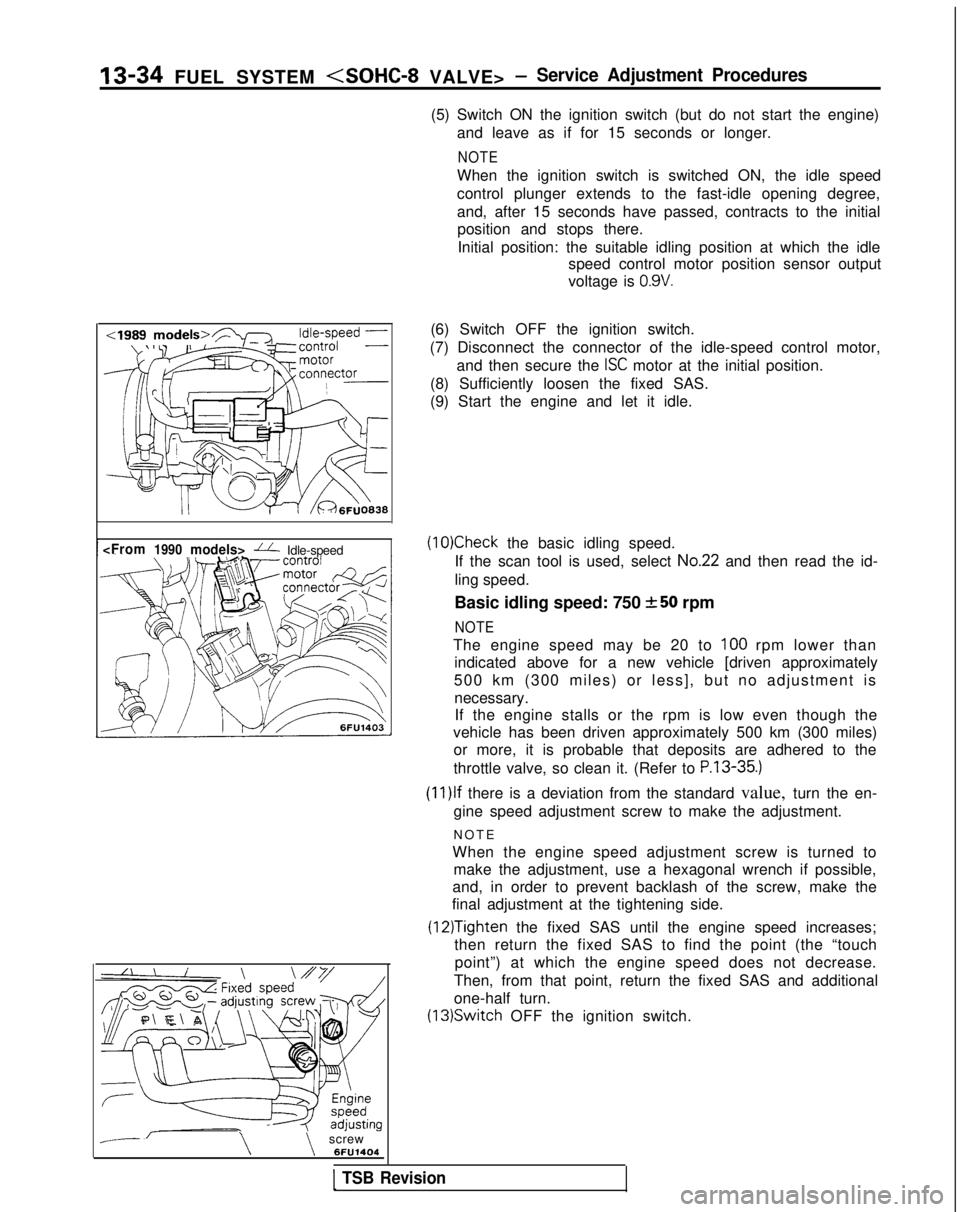
fi Idle-speed
--\\screw 6FU1404(6) Switch OFF the ignition switch.
(7) Disconnect the connector of the idle-speed control motor, and then secure the
ISC motor at the initial position.
(8) Sufficiently loosen the fixed SAS.
(9) Start the engine and let it idle.
(10)Check the basic idling speed.
If the scan tool is used, select
No.22 and then read the id-
ling speed.
Basic idling speed: 750
+-50 rpm
NOTE
The engine speed may be 20 to 100 rpm lower than
indicated above for a new vehicle [driven approximately
500 km (300 miles) or less], but no adjustment is necessary.If the engine stalls or the rpm is low even though the
vehicle has been driven approximately 500 km (300 miles) or more, it is probable that deposits are adhered to the
throttle valve, so clean it. (Refer to
P.13-35.)
(1l)lf there is a deviation from the standard value, turn the en-
gine speed adjustment screw to make the adjustment.
NOT
E
When the engine speed adjustment screw is turned to make the adjustment, use a hexagonal wrench if possible,
and, in order to prevent backlash of the screw, make the
final adjustment at the tightening side.
(12)Tighten the fixed SAS until the engine speed increases;
then return the fixed SAS to find the point (the “touch
point”) at which the engine speed does not decrease.
Then, from that point, return the fixed SAS and additional
one-half turn. (13)Switch
OFF the ignition switch.
1 TSB Revision
Page 177 of 1273

FUEL SYSTEM -Service Adjustment Procedures 13-35
(14)Adjust the play of the accelerator cable. (Refer to P.13-
329.)
(15)Connect the idle-speed control motor’s connector.
(16)Adjust the throttle-position sensor.
(17)Start the engine again and let it run at idle speed for about
ten minutes; check to be sure that the idling condition is
normal.
THROTTLE BODY (THROTTLE VALVE AREA)
CLEANING
MllFlCK
(1)Start the engine and warm it up until the temperature of the
engine coolant reaches
80°C (176°F) or higher; then stop
the engine.
(2) Disconnect the air intake hose at the throttle body side.
(3) Spray cleaning liquid (from the intake port of the throttle body) onto the valve, and then leave as is for about fiveminutes.
(4) Start the engine and race it a few times; then let it run at idle speed for about one minute.
NOTE
If the engine idling speed is unstable (or the engine stalls),
let the engine run with the throttle valve slightly open.
(5) If deposits are not removed from the throttle valve, repeat steps (3) and (4).
(6) Connect the air intake hose.
(7) Using the scan tool, erase the diagnostic trouble code, or disconnect the battery’s ground cable for ten seconds orlonger and then reconnect it.
(8) Adjust the basic idle speed (engine speed adjusting screw). (Refer to
P.13-33.)
(9) Adjust the throttle position sensor.
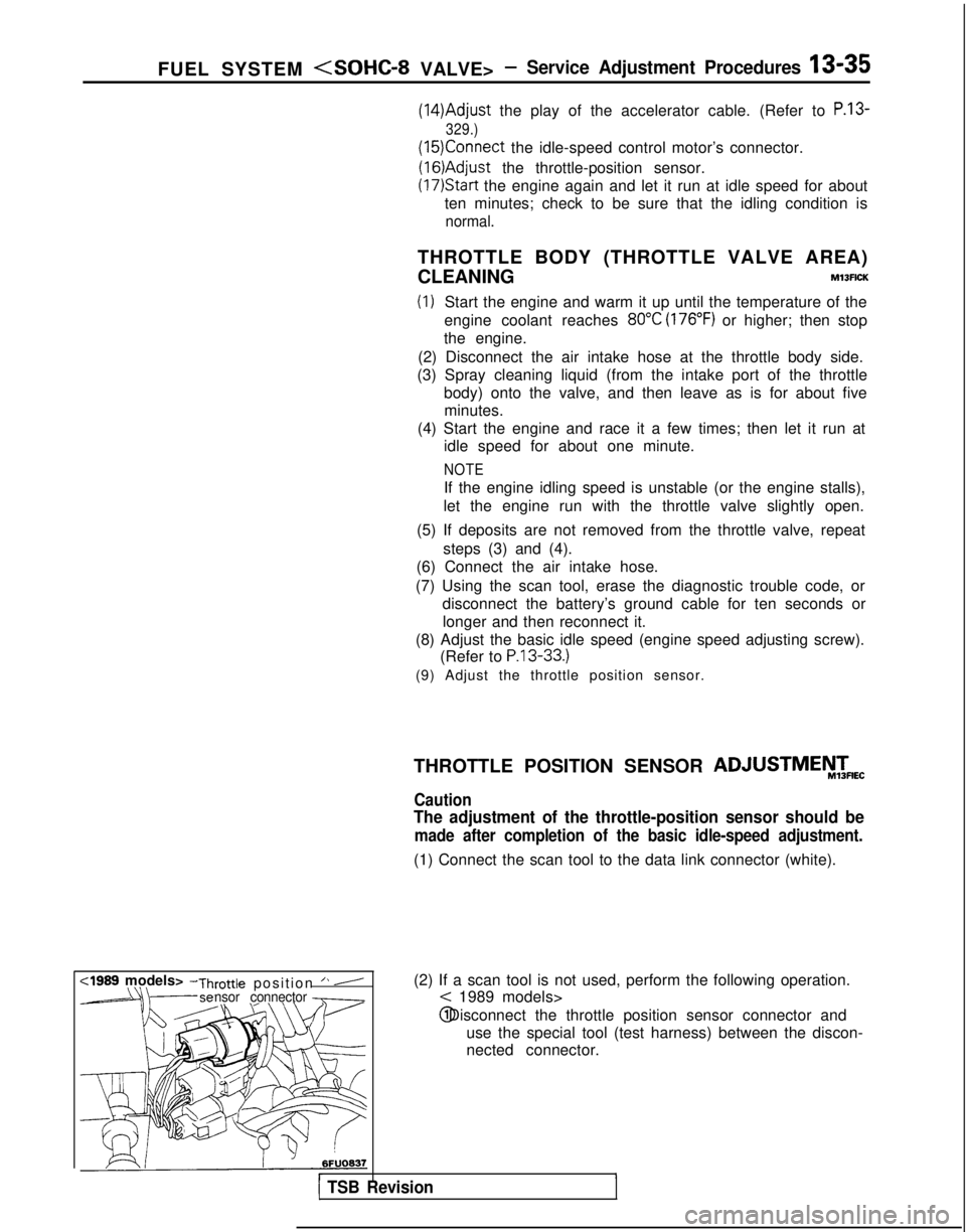
-rottle position ” ynsor connector
(2) If a scan tool is not used, perform the following operation.
< 1989 models> @ Disconnect the throttle position sensor connector and
use the special tool (test harness) between the discon-
nected connector.
r1 TSB Revision
THROTTLE POSITION SENSOR ADJUSTMEiW&
Caution
The adjustment of the throttle-position sensor should be
made after completion of the basic idle-speed adjustment.
(1) Connect the scan tool to the data link connector (white).
,