Page 211 of 1273
FUEL SYSTEM - On-Vehicule lnwection
of MFI Components13-69
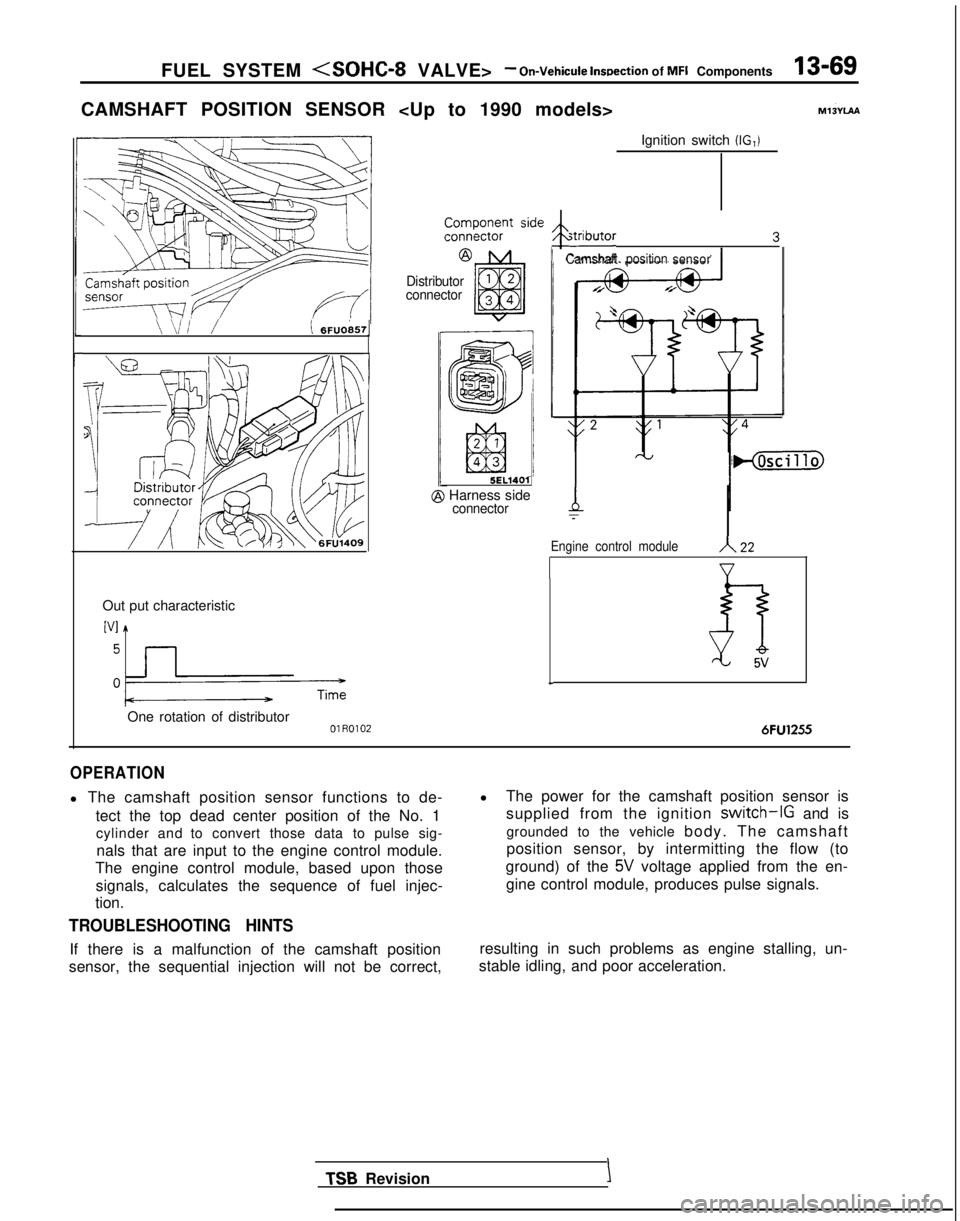
CAMSHAFT POSITION SENSOR
\ /‘4 iI ‘j6FUO857
r
1
Out put characteristic ‘“!I
pm
One rotation of distributorOlR0102
Ignition switch (IG,) ~~~!%k?nt
side ,Distributor4 3
Camshaft position
sensor
Distributor
connector 5EL1401
@ Harness sideconnectorT
Engine control moduleA22
V
L
6FU1255
OPERATION
l The camshaft position sensor functions to de-
tect the top dead center position of the No. 1cylinder and to convert those data to pulse sig-
nals that are input to the engine control module.
The engine control module, based upon those
signals, calculates the sequence of fuel injec-
tion.
TROUBLESHOOTING HINTS
If there is a malfunction of the camshaft position
sensor, the sequential injection will not be correct, l
The power for the camshaft position sensor is
supplied from the ignition
switch-IG and is
grounded to the vehicle body. The camshaft
position sensor, by intermitting the flow (to
ground) of the
5V voltage applied from the en-
gine control module, produces pulse signals.
resulting in such problems as engine stalling, un-
stable idling, and poor acceleration.
TSB RevisionI
Page 213 of 1273
FUEL SYSTEM
VALVE> -On-Vehicule Inspection of MFI Components13-71
CAMSHAFT POSITION SENSOR MlBYU8
sensor/
WV?: (I 6FUO857
Out put charactenstic
I->Time
One rotatton of distributor01 R0102
@ Component side
connector
Ignition switch (IG,)
I
\/\/\/\/\/\/4 2
&T]
f-b
9r
Engine control moduleA 22
h
5v
OPERATION
TROUBLESHOOTING HINTS
INSPECTION-Using Oscilloscope
Refer to P.13-69.
HARNESS INSPECTION
Harness side
connector
@
7FUO49t
r1 TSB Revision Measure the power supply voltage.
. Connector: Disconnected
. Ignition switch: ON
Voltage
(V)
Battery positive voltage
Iswitch)
Page 215 of 1273
FUEL SYSTEM -On-Vehicule
inspection of MFI Components13-73
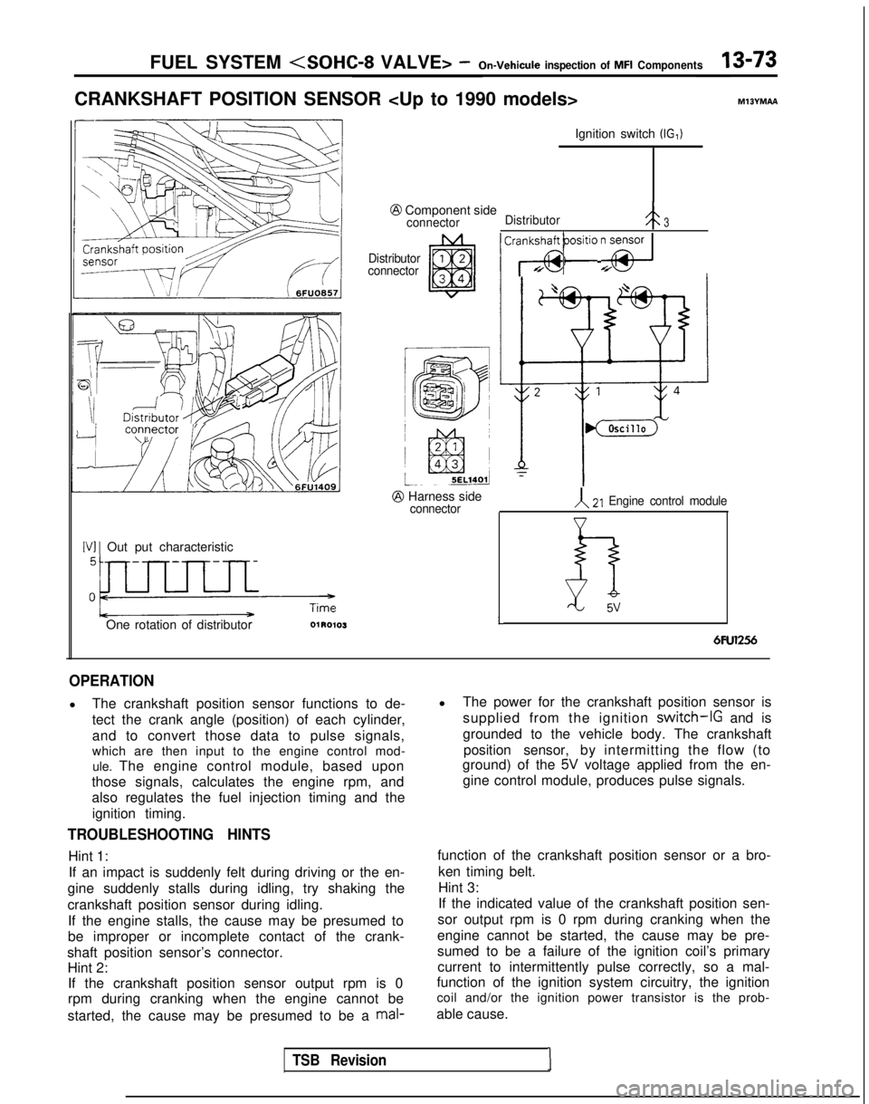
CRANKSHAFT POSITION SENSOR MllYMAA
\IDikZ!utoJP
[VI 1 Out put characteristic
One rotation of distributor Ignition switch
(IG,)
@ Component sideconnector
Distributor3
Distributor
connector
@ Harness sideconnector
/ CraTSiti0 y$/
A21 Engine control module
LD5vLI
6Fu1256
OPERATION
l The crankshaft position sensor functions to de-
tect the crank angle (position) of each cylinder,
and to convert those data to pulse signals,
which are then input to the engine control mod-
ule. The engine control module, based upon
those signals, calculates the engine rpm, and
also regulates the fuel injection timing and the
ignition timing.
TROUBLESHOOTING HINTS
Hint 1:If an impact is suddenly felt during driving or the en-
gine suddenly stalls during idling, try shaking the
crankshaft position sensor during idling. If the engine stalls, the cause may be presumed to
be improper or incomplete contact of the crank-
shaft position sensor’s connector. Hint 2:If the crankshaft position sensor output rpm is 0
rpm during cranking when the engine cannot be
started, the cause may be presumed to be a
mal-
l The power for the crankshaft position sensor is
supplied from the ignition
switch-IG and is
grounded to the vehicle body. The crankshaft position sensor, by intermitting the flow (to
ground) of the
5V voltage applied from the en-
gine control module, produces pulse signals.
function of the crankshaft position sensor or a bro- ken timing belt.
Hint 3:
If the indicated value of the crankshaft position sen-
sor output rpm is 0 rpm during cranking when the
engine cannot be started, the cause may be pre-
sumed to be a failure of the ignition coil’s primary current to intermittently pulse correctly, so a mal-
function of the ignition system circuitry, the ignition
coil and/or the ignition power transistor is the prob-
able cause.
TSB Revision1
Page 216 of 1273
13-74 FUEL SYSTEM
VALVE> -On-Vehicule inspection of MFI Components
Hint 4:
If idling is possible even though the crankshaft posi-
tion sensor indicated rpm is a deviation from the standard value, the cause is usually a malfunction of
something other than the crankshaft position sen-
sor.
Examples:
(1) Malfunction of the coolant-temperature sensor.
(2) Malfunction of the idling-speed control motor.
(3) Improper adjustment of the standard idling
speed.
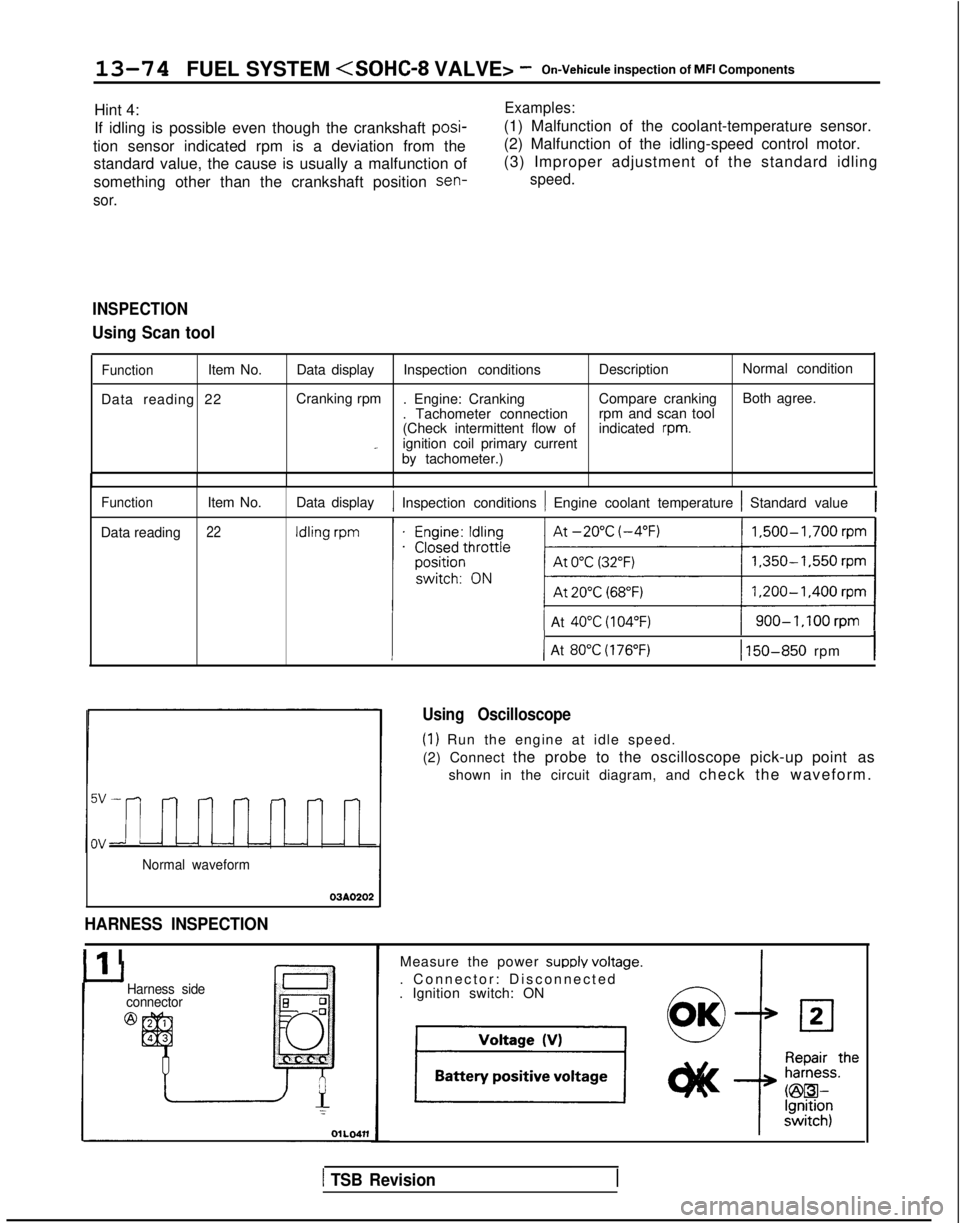
INSPECTION
Using Scan tool
FunctionItem No.
Data reading 22 Data display
Inspection conditions DescriptionNormal condition
Cranking rpm . Engine: Cranking Compare crankingBoth agree.
. Tachometer connection rpm and scan tool
(Check intermittent flow of indicated
rpm._ignition coil primary current
by tachometer.)
Function
Data reading Item No.22
Data display1 Inspection conditions 1 Engine coolant temperature 1 Standard value1
1 At 40°C (104°F)1 900-1,100rpm 1
III-I( At 80°C (176°F)1 150-850 rpm
Normal waveform
03AO202
HARNESS INSPECTION
Ilr I
Using Oscilloscope
(1) Run the engine at idle speed.
(2) Connect the probe to the oscilloscope pick-up point as
shown in the circuit diagram, and check the waveform.
Harness side
connector
@
Measure the power SUPPIY voltaoe.
. Connector: Disconnected
-. Ignition switch: ON
1 TSB Revision
Page 217 of 1273
FUEL SYSTEM
VALVE> -On-Vehicule lnsoection of MFI Comoonents13975
@ Harness srdeconnector
@ Harness sideconnector
Check for continuity of the ground
circuit.
. Connector: Disconnected
1 Reoair the
t
hainess.
(@B-Ground)
Check the voltage of the output cir-
cuit.
. Connector: Disconnected
. ignition switch: ON
u
O
K
ASTOP
Repair the
harness.
(@m-m)
CRANKSHAFT POSITION SENSOR MIBYMAB
m/i /i 6FUO6571
[VI 1 Output characteristic
@ Component sideconnector
Ignition switch (IG1)
One rotation of crankshaftposition sensor
01R0’05
TSB Revision
Engine control module,( 21
m---l 7F”04pp
I
Page 222 of 1273
13-80 FUEL SYSTEM -On-Vehicule Inspection of MFI Components
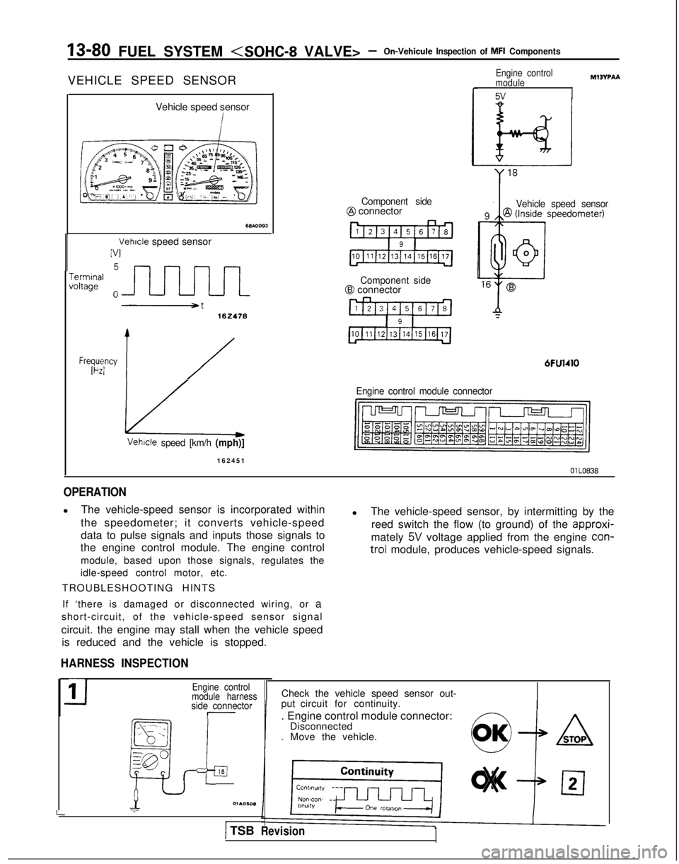
VEHICLE SPEED SENSOR
Vehicle speed sensor
Vehicle speed sensor
IV1
-errnInafoltage
102418
Frwyy 1/
Component side@ connector
Component side@ connector
6FU1410
Engine control
module
5v
MIBVPAA
Vehicle speed sensor
Engine control module connector Vetwle
speed [km/h (mph)]
16245
1
OlLO838
OPERATION
l
The vehicle-speed sensor is incorporated within
the speedometer; it converts vehicle-speed
data to pulse signals and inputs those signals to
the engine control module. The engine control
module, based upon those signals, regulates the
idle-speed control motor, etc.
TROUBLESHOOTING HINTS l
The vehicle-speed sensor, by intermitting by the
reed switch the flow (to ground) of the approxi-
mately
5V voltage applied from the engine con-
trol
module, produces vehicle-speed signals.
If ‘there is damaged or disconnected wiring, or a
short-circuit, of the vehicle-speed sensor signal
circuit. the engine may stall when the vehicle speed is reduced and the vehicle is stopped.
HARNESS INSPECTION
-side connector
_--- _
ia
_, - .,
:_--
gp
p
L
11Engine control
module harness
=l01AOW(1
I
Check the vehicle speed sensor out-
put circuit for continuity.
. Engine control module connector: Disconnected
. Move the vehicle.
) TSBRevision
Page 223 of 1273
FUEL SYSTEM - On-Vehicule Inspection of MFI Components13-81
@ Harness sideconnector
6FU1265
n
8171615141312 11 9 1171615141312~1~1
0
I
Measure the power supply voltage of
the vehicle speed sensor.
. Connector: Disconnected
. Ignition switch: ON
6&loIw I
Voltage (V)
I4.5-4.9--I
Repair theharness.
II
I
Check for continuity of the ground
circuit.
Connector: Disconnected
Repair the
harness.
@WGround)
SENSOR INSPECTION
Refer to GROUP 54-Meters and Gauges.
POWER STEERING PRESSURE SWITCH MI3Yclha
------LI~lI I’ 6FUO65f
TSB Revision
Engine
Power steering 1@
blHarness sideconnector
Enoine control module connector
Page 227 of 1273
FUEL SYSTEnrll (SOHC-8 VALVE> -On-Vehicule
Inspection of MFI Components13-85
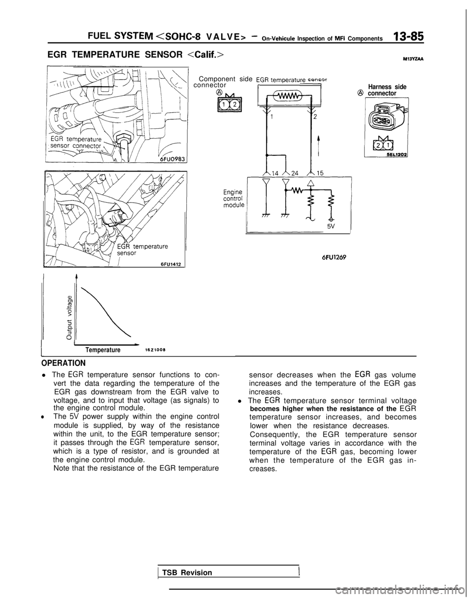
EGR TEMPERATURE SENSOR Ml3Yza
\+\+I connectorComponent side EGR temperaturn r-n~nrrHarness side@
connector 6FlJ1412
1
IwTemperaturelEzlooB
OPERATION
l The EGR temperature sensor functions to con-
vert the data regarding the temperature of the EGR gas downstream from the EGR valve to
voltage, and to input that voltage (as signals) to
the engine control module.
lThe 5V power supply within the engine control
module is supplied, by way of the resistance
within the unit, to the EGR temperature sensor; it passes through the
EGR temperature sensor,
which is a type of resistor, and is grounded at
the engine control module. Note that the resistance of the EGR temperature
6FU1269
sensor decreases when the EGR gas volume
increases and the temperature of the EGR gas
increases.
l The EGR temperature sensor terminal voltage
becomes higher when the resistance of the EGR
temperature sensor increases, and becomes
lower when the resistance decreases.
Consequently, the EGR temperature sensor
terminal voltage varies in accordance with the
temperature of the
EGR gas, becoming lower
when the temperature of the EGR gas in-
creases.
TSB RevisionI