1989 MITSUBISHI GALANT low beam
[x] Cancel search: low beamPage 253 of 1273
FUEL SYSTEM
03R0297
Vapor hose
mmin.)Fillerhose
i2.l
B
3FOO7
A
1
Flare nut
Skure side
03Yo43
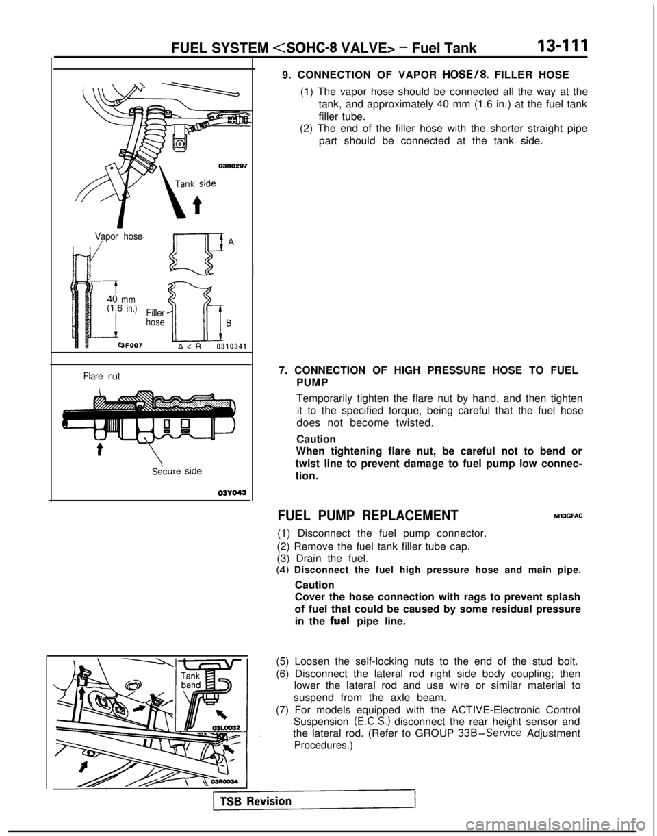
9. CONNECTION OF VAPOR HOSE/8. FILLER HOSE
(1) The vapor hose should be connected all the way at the tank, and approximately 40 mm (1.6 in.) at the fuel tank
filler tube.
(2) The end of the filler hose with the shorter straight pipe
part should be connected at the tank side.
7. CONNECTION OF HIGH PRESSURE HOSE TO FUEL PUMP
Temporarily tighten the flare nut by hand, and then tightenit to the specified torque, being careful that the fuel hose
does not become twisted.
Caution
When tightening flare nut, be careful not to bend or
twist line to prevent damage to fuel pump low connec-
tion.
FUEL PUMP REPLACEMENT
(1) Disconnect the fuel pump connector.
(2) Remove the fuel tank filler tube cap.
(3) Drain the fuel. MllGFAC
(4)
Disconnect the fuel high pressure hose and main pipe.
Caution
Cover the hose connection with rags to prevent splash
of fuel that could be caused by some residual pressure in the
fuel. pipe line.
(5) Loosen the self-locking nuts to the end of the stud bolt.
(6) Disconnect the lateral rod right side body coupling; then lower the lateral rod and use wire or similar material to
suspend from the axle beam.
(7) For models equipped with the ACTIVE-Electronic Control Suspension
(E.C.S.) disconnect the rear height sensor and
the lateral rod. (Refer to GROUP
33B-Service Adjustment
Procedures.)
Page 462 of 1273
13-320FUEL SYSTEM
03RO297
V/apor hose
mmin.)
3FOO7
Filler
hoseB
A
\Secure side 03YO43
Ll
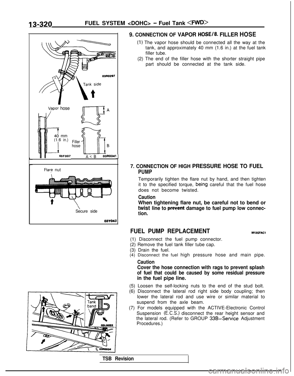
9. CONNECTION OF VAPOR HOSE/8. FILLER HOSE
(1) The vapor hose should be connected all the way at the
tank, and approximately 40 mm (1.6 in.) at the fuel tank
filler tube.
(2) The end of the filler hose with the shorter straight pipe part should be connected at the tank side.
7. CONNECTION OF HIGH PRESSURE HOSE TO FUEL
PUMP
Temporarily tighten the flare nut by hand, and then tighten
it to the specified torque,
bein,g careful that the fuel hose
does not become twisted.
Caution
When tightening flare nut, be careful not to bend or
twist line to prevent damage to fuel pump low connec-
tion.
FUEL PUMP REPLACEMENT
(1) Disconnect the fuel pump connector.
(2) Remove the fuel tank filler tube cap.
(3) Drain the fuel.
Ml3GFAt.X
(4) Disconnect the fuel high pressure hose and main pipe.
Caution
Cover the hose connection with rags to prevent splash
of fuel that could be caused by some residual pressure
in the fuel pipe line.
(5) Loosen the self-locking nuts to the end of the stud bolt.
(6) Disconnect the lateral rod right side body coupling; then
lower the lateral rod and use wire or similar material to
suspend from the axle beam.
(7) For models equipped with the ACTIVE-Electronic Control Suspension
(E.C.S.) disconnect the rear height sensor and
the lateral rod. (Refer to GROUP
33B-Service Adjustment
Procedures.)
TSB Revision
Page 944 of 1273
ACTIVE-ELECTRONIC CONTROL SUSPENSION - Specifications33B-5
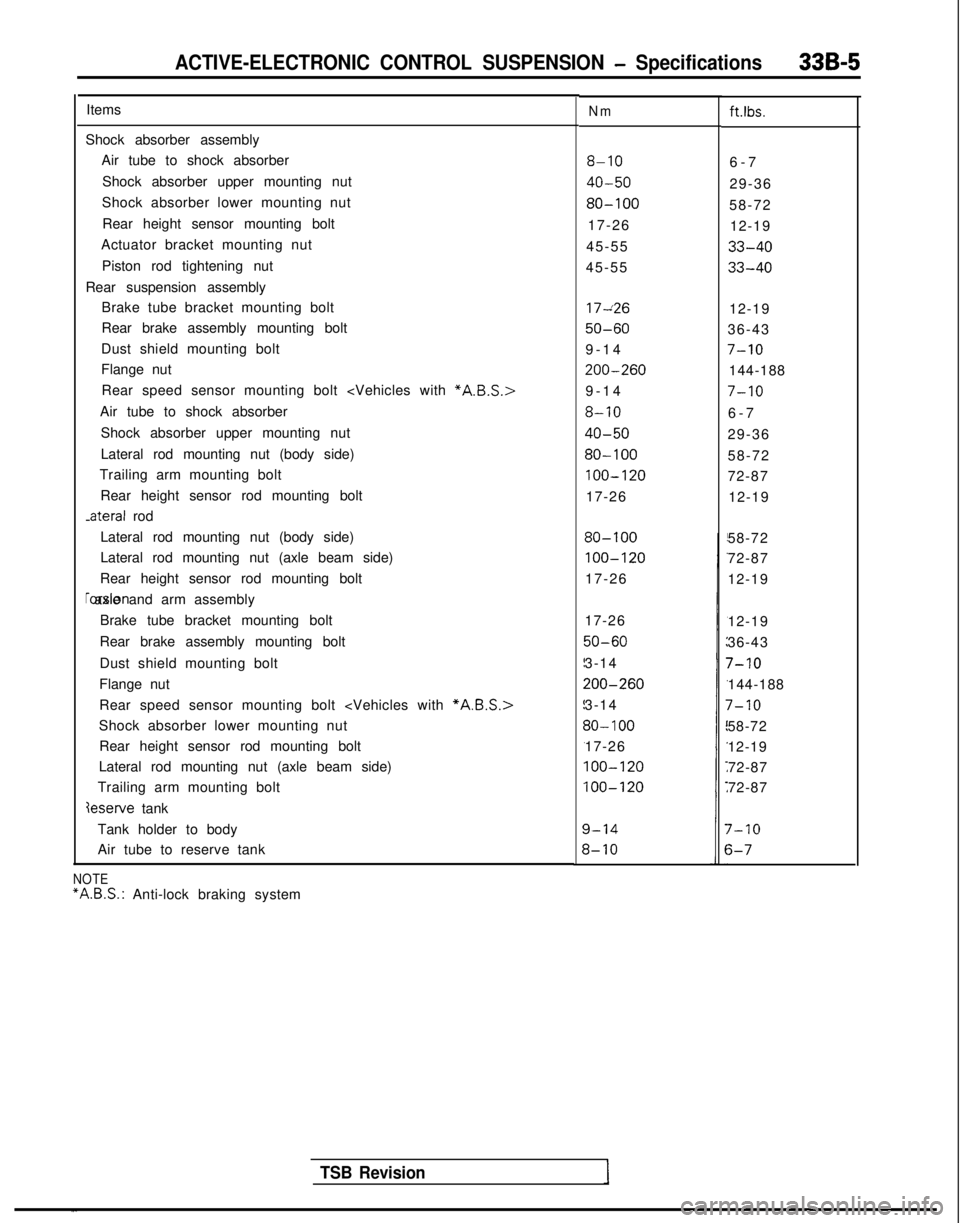
ItemsNmft.lbs.
Shock absorber assemblyAir tube to shock absorber
Shock absorber upper mounting nut
Shock absorber lower mounting nut
Rear height sensor mounting bolt
Actuator bracket mounting nut
Piston rod tightening nut
Rear suspension assembly Brake tube bracket mounting bolt
Rear brake assembly mounting bolt
Dust shield mounting bolt
Flange nut
8-106-
7
40-5029-36
80-10058-72
17-26 12-19
45-55
33-40
45-5533-40
Rear speed sensor mounting bolt
Air tube to shock absorber
Shock absorber upper mounting nut
Lateral rod mounting nut (body side)
Trailing arm mounting bolt
Rear height sensor rod mounting bolt -ateral
rod 17~26
12-19
50-6036-43
9-1
4
7-10
200-260144-188
9-1
4
7-10
8-106-
7
40-5029-36
80-10058-72
100-12072-87
17-26 12-19
Lateral rod mounting nut (body side)
Lateral rod mounting nut (axle beam side)
Rear height sensor rod mounting bolt rorsion axle and arm assembly
Brake tube bracket mounting bolt
Rear brake assembly mounting bolt
Dust shield mounting bolt
Flange nut
80-100
100-120
17-26 58-72
72-87
12-19
Rear speed sensor mounting bolt
Shock absorber lower mounting nut Rear height sensor rod mounting bolt
Lateral rod mounting nut (axle beam side)
Trailing arm mounting bolt
deserve tank 17-26
50-60
3-14
200-260
3-14
30- 100
17-26
100-120
100-120
12-19
36-43
7-10
144-188
7-10
58-72
12-19
72-87
72-87
Tank holder to body
Air tube to reserve tank
7-10
s-7
TSB Revision
NOTE “A.B.S.:
Anti-lock braking system
Page 978 of 1273
ACTIVE-ELECTRONIC CONTROL SUSPENSION - Troubleshooting 33B-39
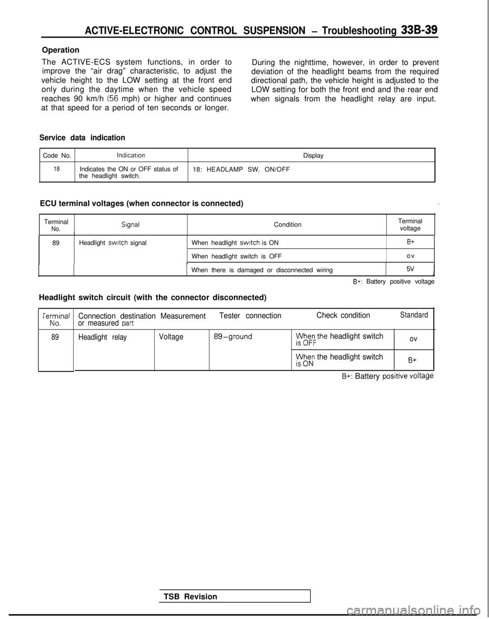
Operation
The ACTIVE-ECS system functions, in order to improve the “air drag” characteristic, to adjust the During the nighttime, however, in order to prevent
vehicle height to the LOW setting at the front end deviation of the headlight beams from the required
only during the daytime when the vehicle speed directional path, the vehicle height is adjusted to the
reaches 90 km/h
(56 mph) or higher and continues LOW setting for both the front end and the rear end
at that speed for a period of ten seconds or longer. when signals from the headlight relay are input.
Service data indication
Code No.lndlcation
Display
18Indicates the ON or OFF status of
18: HEADLAMP SW. ON/OFF
the headlight switch.
ECU terminal voltages (when connector is connected)
/
TerminalNo. Slgnal
ConditionTerminal
voltage
89 Headlight switch
signal When headlight
switch is ON
When headlight switch is OFFB+
o
v
When there is damaged or disconnected wiring
5vJ
B+: Battery positive voltage
Headlight switch circuit (with the connector disconnected)
TSB Revision
TeKJna’
89
Connection destination Measurement Tester connectionCheck conditionStandard
or measured Dart
Headlight relayVoltage 89-groundph&the headlight switchov
rt$z; the headlight switchB+
~.A.-II___B+: Battery posrrrve voltage
Page 981 of 1273
![MITSUBISHI GALANT 1989 Service Repair Manual 33B-42
ACTIVE-ELECTRONIC CONTROL SUSPENSION - Troubleshooting
IO] FRONT-HEIGHT SENSOR CIRCUIT
.ever
Seysor
,..e
Relationship between N (normal vehicle height) and othervehicle-height levels
High 1
No](/manual-img/19/57312/w960_57312-980.png "MITSUBISHI GALANT 1989 Service Repair Manual 33B-42
ACTIVE-ELECTRONIC CONTROL SUSPENSION - Troubleshooting
IO] FRONT-HEIGHT SENSOR CIRCUIT
.ever
Seysor
,..e
Relationship between N (normal vehicle height) and othervehicle-height levels
High 1
No")
33B-42
ACTIVE-ELECTRONIC CONTROL SUSPENSION - Troubleshooting
IO] FRONT-HEIGHT SENSOR CIRCUIT
.ever
Seysor
,..e
Relationship between N (normal vehicle height) and othervehicle-height levels
High 1
Normal 50
(1.97)
40(1.57)
30(1.18)
201.791
10C.39)
0
tEH (highest)._--
HH (higher than HIGH)
H (HIGH vehicle height)
NH (higher
than NORM)
N (NORMAL vehicle height)
EL (lowest) A-27
[Unit: mm
(in.11
Front-helghf
sensor
Operation
The front-height sensor detects (by detecting the
sistors, and the slits in the disc thus interrupt, or let
relative position of the body and the front axle) the
action movements (bouncing, nose diving, etc.), pass, the light beams between the light-emitting
diodes and the photo-transistors. By employing the data gathered in this way, the
sen-
sor can detect the vehicle height as any one of the
nine level classifications.
and the vehicle height, of the front of the vehicle,
The rotating disc plate rotates in the area between
four pairs of light-emitting diodes and photo-tran-
TSB Revision
Page 983 of 1273
![MITSUBISHI GALANT 1989 Service Repair Manual 33B-44 ACTIVE-ELECTRONIC CONTROL SUSPENSION - Troubleshooting
[ll] REAR-HEIGHT SENSOR CIRCUIT
1989 models
F-18
-1
F-l 9
pjimlq
piTgs%q
c-07
D-27
G-05
High
I
Normal50 (1.97)
4..:::.:.:_~-.^::::::::“.](/manual-img/19/57312/w960_57312-982.png "MITSUBISHI GALANT 1989 Service Repair Manual 33B-44 ACTIVE-ELECTRONIC CONTROL SUSPENSION - Troubleshooting
[ll] REAR-HEIGHT SENSOR CIRCUIT
1989 models
F-18
-1
F-l 9
pjimlq
piTgs%q
c-07
D-27
G-05
High
I
Normal50 (1.97)
4..:::.:.:_~-.^::::::::“.")
33B-44 ACTIVE-ELECTRONIC CONTROL SUSPENSION - Troubleshooting
[ll] REAR-HEIGHT SENSOR CIRCUIT
1989 models
F-18
-1
F-l 9
pjimlq
piTgs%q
c-07
D-27
G-05
High
I
Normal50 (1.97)
4..:::.:.:_~-.^::::::::“.“::i
+E
jr;::::::::::_:
40 (1.57)
30 (1.18)
LowI[Unit: mm (in.11
ECU
1 Rear vehicle-height/fisjnmy3tp I (I
Rear-height sensor12AQ414
-LL (lower than LOW) HH (higher than HIGH)
H (HIGH vehicle height)
NH (higher than NORM)
N (NORMAL vehicle height)
NL (lower than NORM)
L (LOW vehicle height)
12AO182
Operation
The rear-height sensor detects (by detecting the relative position of the body and the rear axle) the
action movements (bouncing, pitching, etc.), and
the vehicle height, of the rear of the vehicle. The
rotating disc plate rotates in the area between three
pairs of light-emitting diodes and photo-transistors, and the slits in the disc thus interrupt, or let pass.
the light beams between the light-emitting diodes
and the photo-transistors. By employing the datagathered in this way, the sensor can detect the vehi-
cle height as any one of the seven level
classifica-
tions.
TSB Revision
Page 1049 of 1273
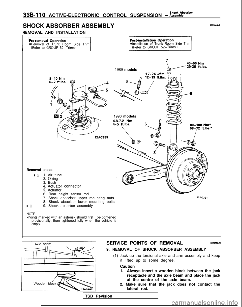
33B-110 ACTIVE-ELECTRONIC CONTROL SUSPENSION - i=ttbborber
SHOCK ABSORBER ASSEMBLYhl33MA-A[EMOVAL
AND INSTALLATION
1989 models
40-50 Nm
29-36 ft.lbs.
Removal
l *
l *
8-10 Nm
steps
1.Air tube2.O-ring3.Bush4.Actuator connector5.Actuator6. Rear height sensor rod
6
17-26 Nm 9127 ft.lbs;.i
1990 modelsz??
4.8-7.2 Nm
4-5 ftlbs.
\
6 80-100
Nm*
58-72
ft.lbs.*
7. Shock at%orber
upper mounting nuts
8. Shock absorber lower mounting bolts
9. Shock absorber assemblyWA0331
NOTE *: Points marked with an asterisk should first
be tightened
provisionally, then tightened fully when the vehicle is
empty.
SERVICE POINTS OF REMOVALm33hlsN
9. REMOVAL OF SHOCK ABSORBER ASSEMBLY
(1) Jack up the torsional axle and arm assembly and keep it lifted up to some degree.
Caution
1.Always insert a wooden block between the jack receptacle and the axle beam and place the jack
at the centre of the axle beam.
2. Make sure that the jack does not contact the lateral rod.
TSB Revision
Page 1055 of 1273
33B-116 ACTIVE-ELECTRONIC CONTROL SUSPENSION - z%rension
‘3.
Apply rubber grease
1Paint
Install at the shockabsorber side.
12A0327
19. REMOVAL OF SHOCK ABSORBER UPPER MOUNTING
NUTS/PO. TRAILING ARM MOUNTING
BOLTS/Zl.
REAR SUSPENSION ASSEMBLY
(1) Jack up the torsion axle and arm assembly in order to raise it slightly.
Caution 1. Always insert a wooden block between the jack receptacle and the axle beam and place the jack
at the centre of the axle beam.
2. Make sure that the jack does not contact the lateral rod.
(2) Remove the shock absorber mounting bolts and the trailing arm mounting bolts.
(3) Lower the jack slowly, and then remove the rear
suspension assembly.
INSPECTION
M33GCBC
l Check the trailing arm and axle beam for deformation or
damage.
l Check the torsion bar for damage.
l Check the lateral rod for damage or deformation.
l Check the bushings for cracking, deterioration, or unusual
wear.
BUSHING REPLACEMENT
TRAILING ARM BUSHING
Refer to
P.33B-121.
LATERAL ROD BUSHINGRefer to
P.33B-118.
SERVICE POINTS OF INSTALLATIONM33GDSC
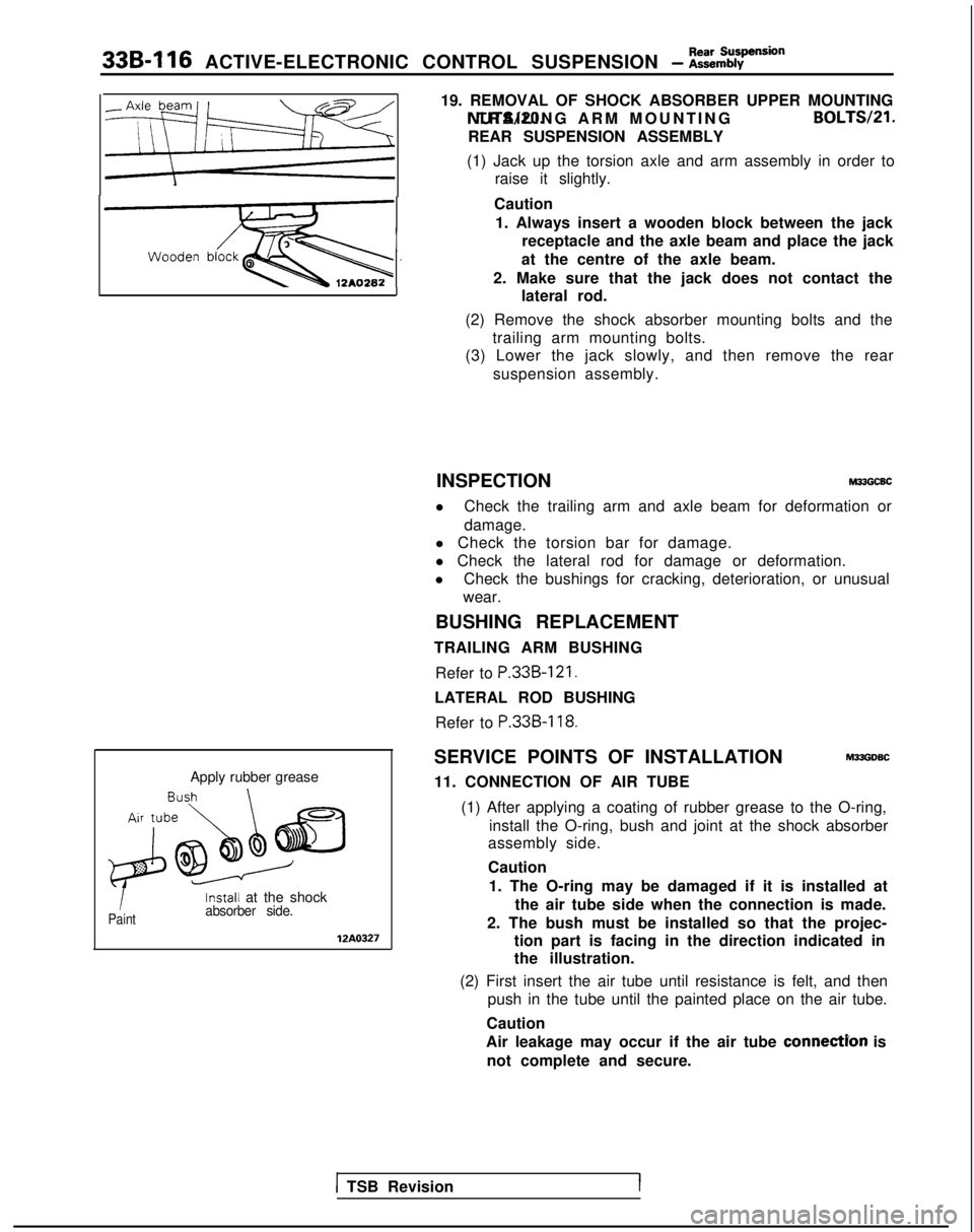
11. CONNECTION OF AIR TUBE
(1) After applying a coating of rubber grease to the O-ring, install the O-ring, bush and joint at the shock absorber
assembly side.
Caution
1. The O-ring may be damaged if it is installed at the air tube side when the connection is made.
2. The bush must be installed so that the projec- tion part is facing in the direction indicated in
the illustration.
(2) First insert the air tube until resistance is felt, and then push in the tube until the painted place on the air tube.
Caution
Air leakage may occur if the air tube
connectYon is
not complete and secure.
1 TSB RevisionI