Page 1059 of 1273
33B-120 ACTIVE-ELECTRONIC CONTROL SUSPENSION - Z%iZky8”d
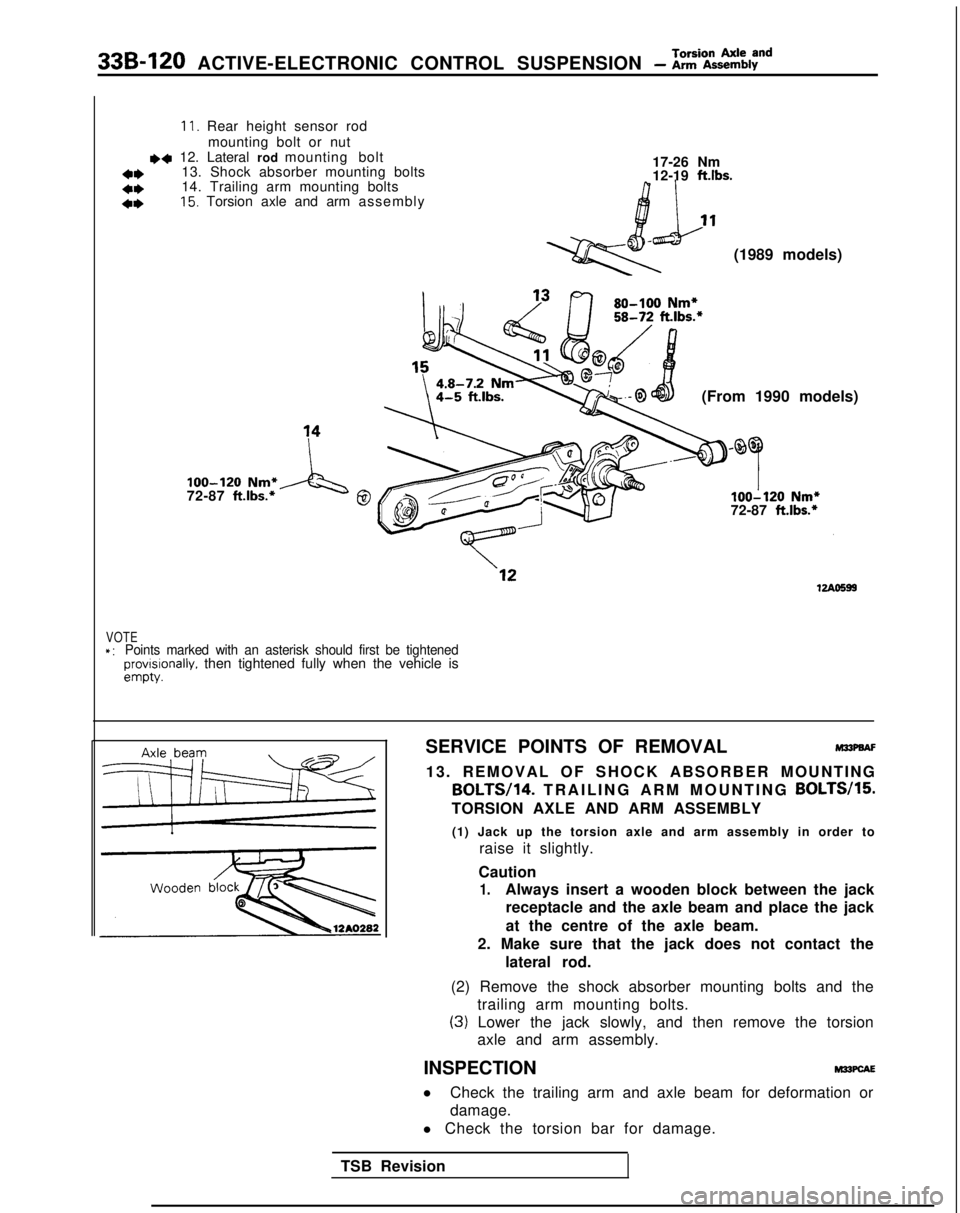
11. Rear height sensor rodmounting bolt or nut
~~ 12. Lateral rod mounting bolt
13. Shock absorber mounting bolts 17-26 Nm
a*12-19 ftlbs.*I)14. Trailing arm mounting bolts
4*15. Torsion axle and arm assembl
y
(1989 models)
(From 1990 models)
loo-120 Nm*
72-87 ft.lbs.*A‘g0loo-120 Nm*
72-87 ft.lbs.*
VOTE*:Points marked with an asterisk should first be tightenedprovrslonally. then tightened fully when the vehicle isempty.
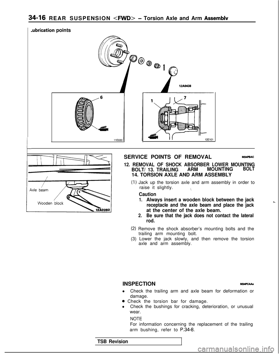
SERVICE POINTS OF REMOVALM33PaAF
13. REMOVAL OF SHOCK ABSORBER MOUNTING BOLTW14.
TRAILING ARM MOUNTING BOLTW15.
TORSION AXLE AND ARM ASSEMBLY
(1) Jack up the torsion axle and arm assembly in order to raise it slightly.
Caution
1.Always insert a wooden block between the jack receptacle and the axle beam and place the jack
at the centre of the axle beam.
2. Make sure that the jack does not contact the lateral rod.
(2) Remove the shock absorber mounting bolts and the trailing arm mounting bolts.
(3) Lower the jack slowly, and then remove the torsionaxle and arm assembly.
INSPECTION
M22PcAE
l Check the trailing arm and axle beam for deformation or
damage.
l Check the torsion bar for damage.
TSB Revision
Page 1085 of 1273
34-4REAR SUSPENSION -Specifications/Special Tools
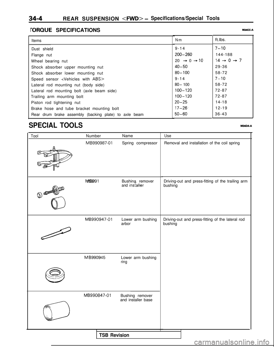
rORQUE SPECIFICATIONSt&4X-A
Items
Dust shield
Flange nut
Wheel bearing nut Shock absorber upper mounting nut
Shock absorber lower mounting nut
Speed sensor
ABS>
Lateral rod mounting nut (body side)
Lateral rod mounting bolt (axle beam side)
Trailing arm mounting bolt
Piston rod tightening nut
Brake hose and tube bracket mounting boltRear drum brake assembly (backing plate) to axle beam
SPECIAL TOOLSM34DA-A
ToolNumber Name MB990987-01
Spring compressor MB991 159
Bushina remover
and insraIler
MB990947-01
Lower arm bushing
arbor M
B990945
Lower arm bushingring MB990847-01
Bushing remover
and installer base
Nmft.lbs.
9-1
4
7-10
200-260144-188
20
+ 0 + IO14-+0+7
40-5029-36
80- 10058-72
9-1
4
7-10
80- 10058-72
100-12072-87
100-12072-87
20-2514-18
17-26,12-19
50-6036-43
Use
Removal and installation of the coil spring
Driving-out and press-fitting of the trailing arm
bushing
Driving-out and press-fitting of the lateral rod
bushing
TSB Revision
Page 1088 of 1273
REAR SUSPENSION - Rear Suspension Assembly
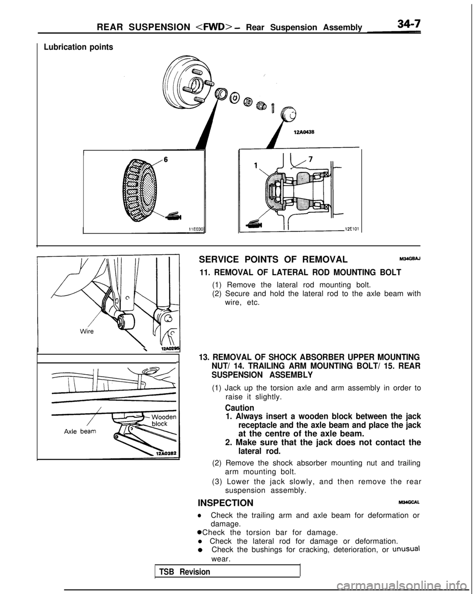
Lubrication points
12ElOl
SERVICE POINTS OF REMOVALM34GsAJ
11. REMOVAL OF LATERAL ROD MOUNTING BOLT
(1) Remove the lateral rod mounting bolt.
(2) Secure and hold the lateral rod to the axle beam with
wire, etc.
\
13. REMOVAL OF SHOCK ABSORBER UPPER MOUNTING-INUT/ 14. TRAILING ARM MOUNTING BOLT/ 15. REAR
SUSPENSION ASSEMBLY
(1) Jack up the torsion axle and arm assembly in order to
raise it slightly.
Caution1. Always insert a wooden block between the jack
receptacle and the axle beam and place the jack
at the centre of the axle beam.
2. Make sure that the jack does not contact the
lateral rod.
(2) Remove the shock absorber mounting nut and trailing arm mounting bolt.
(3) Lower the jack slowly, and then remove the rear suspension assembly.
INSPECTION
M34Glxl.
lCheck the trailing arm and axle beam for deformation or
damage. 0 Check the torsion bar for damage.
l Check the lateral rod for damage or deformation. 0
Check the bushings for cracking, deterioration, or
unusual
wear.
TSB Revision
Page 1089 of 1273
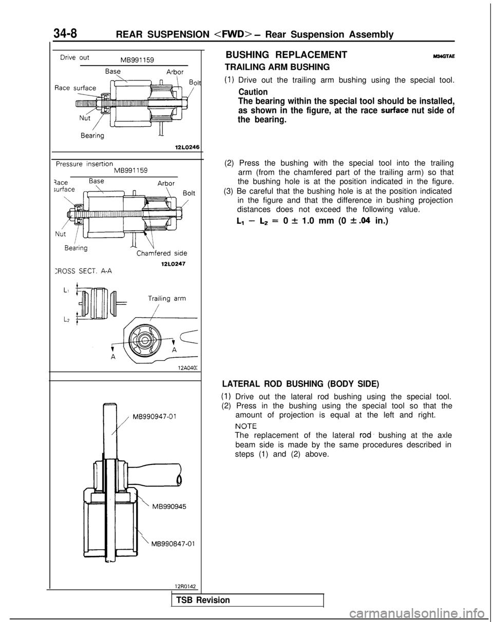
Drive out
Race
BUSHING REPLACEMENTM34GlAEMB991 159
BaseArborTRAILING ARM BUSHING
Oh(1) Drive out the trailing arm bushing using the special tool.
Caution
34-8REAR SUSPENSION - Rear Suspension Assembly
The bearing within the special tool should be installed,
as shown in the figure, at the race
surface nut side of
the bearing.
12LO246
Pressure insertionMB991159
XOSS SECT. A-A
Chamfered side
12LO247
12A040: k
MB990947-01
’ MB990945
\MB990847-01
12R0142(2) Press the bushing with the special tool into the trailing
arm (from the chamfered part of the trailing arm) so that
the bushing hole is at the position indicated in the figure.
(3) Be careful that the bushing hole is at the position indicated in the figure and that the difference in bushing projection
distances does not exceed the following value.
l-1 -L2 =0 f 1.0 mm (0 f .04 in.)
LATERAL ROD BUSHING (BODY SIDE)
(1) Drive out the lateral rod bushing using the special tool.
(2) Press in the bushing using the special tool so that the amount of projection is equal at the left and right. NOTE
The replacement of the lateral rod’
bushing at the axle
beam side is made by the same procedures described in
steps (1) and (2) above.
TSB Revision
Page 1092 of 1273
REAR SUSPENSION - Shock Absorber Assemblv
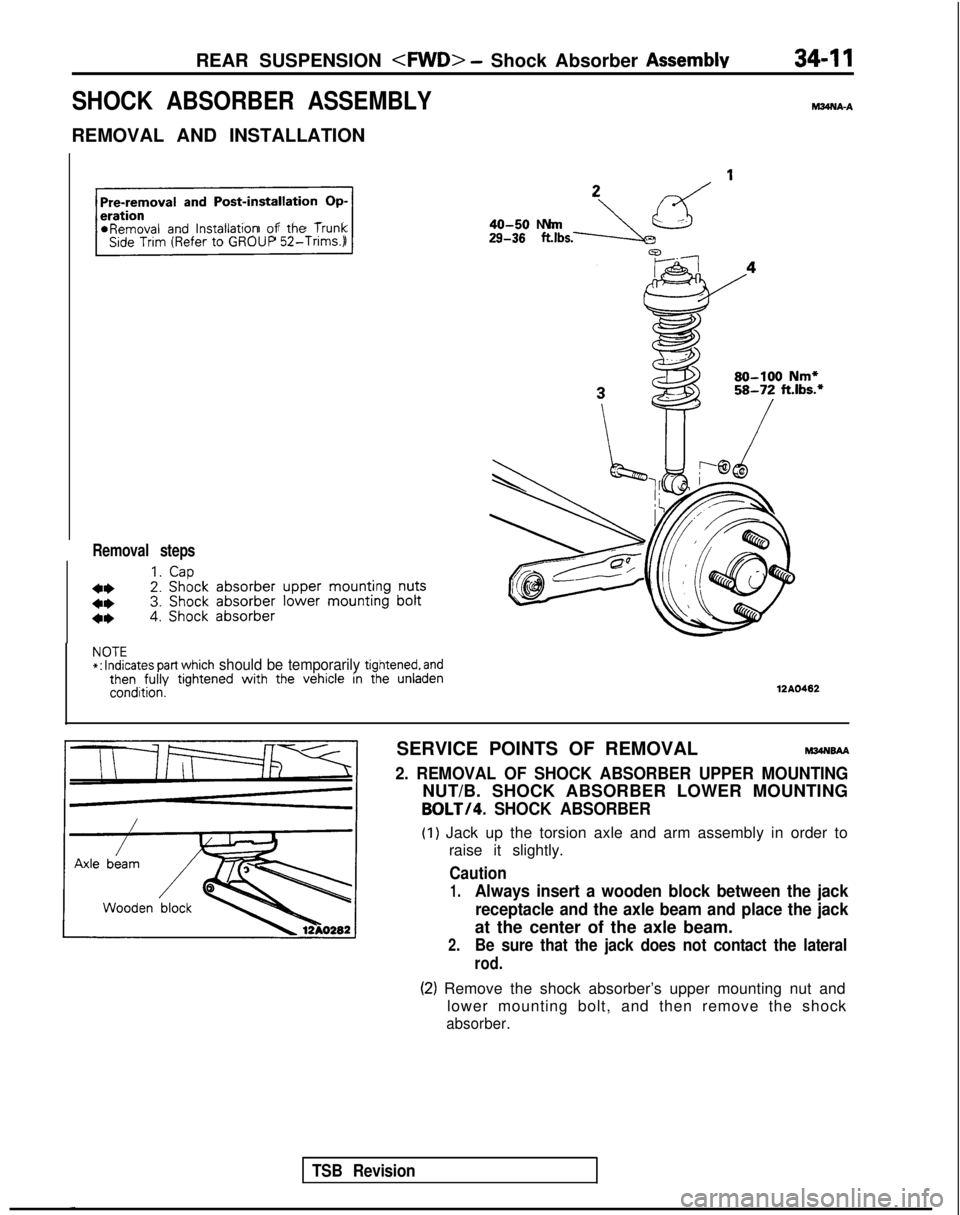
SHOCK ABSORBER ASSEMBLY
REMOVAL AND INSTALLATION
hl34NA-A
Pre-removal
and Post-installation Op-
r
*Removal and lnstallatlon of the TrunkSide Trim (Refer to GROUP
52-Trims.)
Removal steps
1.Cap
4*2. Shock
absorber
upper
mounting
nuts
4*3. Shock
absorber
lower mounting
bolt
4*4. Shock absorber
29-38 .,bs.-JLzd ’40-50 N
m
80-100 Nm*58-72 ft.lbs.*
NOTE*:
Indicates part which should be temporarily tightened, andthen fully
tightened with
the vehicle in the unladencondition.12AO462
TSB Revision
SERVICE POINTS OF REMOVALM34NsAA
2. REMOVAL OF SHOCK ABSORBER UPPER MOUNTING
NUT/B. SHOCK ABSORBER LOWER MOUNTING
BOLT/4. SHOCK ABSORBER
(1) Jack up the torsion axle and arm assembly in order to
raise it slightly.
Caution
1.Always insert a wooden block between the jack
receptacle and the axle beam and place the jack
at the center of the axle beam.
2.Be sure that the jack does not contact the lateral
rod.
(2) Remove the shock absorber’s upper mounting nut and lower mounting bolt, and then remove the shock
absorber.
Page 1097 of 1273
34-16 REAR SUSPENSION - Torsion Axle and Arm Assemblv
L
.ubrication points
12ElOl
SERVICE POINTS OF REMOVALM34PBAC
12. REMOVAL OF SHOCK ABSORBER LOWER MOUNTING
BOLT/ 13. TRAILINGARM
MOUNTINGBOLT
14. TORSION AXLE AND ARM ASSEMBLY
(1) Jack up the torsion axle and arm assembly in order to
raise it slightly.
I
Caution
1.Always insert a wooden block between the jack
receptacle and the axle beam and place the jackh
at the center of the axle beam.
2.Be sure that the jack does not contact the lateral
rod.
(2) Remove the shock absorber’s mounting bolts and the trailing arm mounting bolt.
(3) Lower the jack slowly, and then remove the torsion axle and arm assembly.
INSPECTION
l Check the trailing arm and axle beam for deformation or
damage.
0 Check the torsion bar for damage.
lCheck the bushings for cracking, deterioration, or unusual
wear.
NOTE
For information concerning the replacement of the trailing
arm bushing, refer to
P.34-8.
TSB Revision