1989 MITSUBISHI GALANT compression ratio
[x] Cancel search: compression ratioPage 28 of 1273
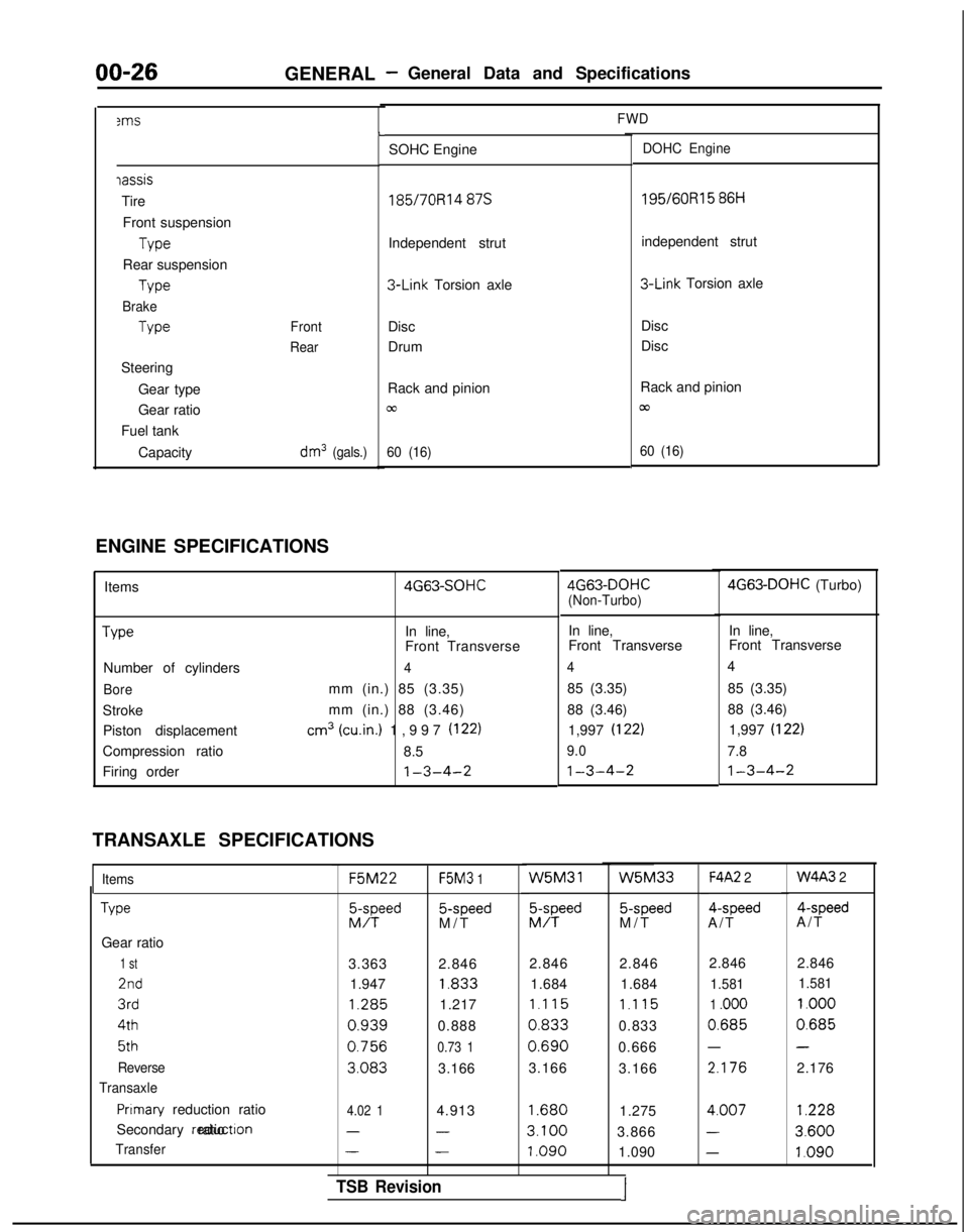
00-263ms
GENERAL -General Data and Specifications
FWD
iassis
Tire
Front suspension Type
Rear suspension Type
Brake
Type
Steering Gear type
Gear ratio
Fuel tank
Capacity
Front
Rear
dm3 (gals.)
L
SOHC EngineDOHC Engine
185/7ORl4 87s 195/60R15
86H
Independent strut independent strut 3-Link
Torsion axle 3-Link
Torsion axle
Disc
Drum Disc
Disc
Rack and pinion
cc
60 (16)
Rack and pinion
/cu
60 (16)
ENGINE SPECIFICATIONS Items Type
Number of cylinders
Bore
StrokePiston displacement
Compression ratio
Firing order 4G63-SOHC
In line,
Front Transverse
4
mm (in.) 85 (3.35)
mm (in.) 88 (3.46)
cm3 (win.) 1,997 (122)
8.5
1-3-4-2
TRANSAXLE SPECIFICATIONS
Items
Type
Gear ratio
1 st
2nd
3rd 4th
5th
Reverse
Transaxle
Pnmary reduction ratio
Secondary reductron ratio
Transfer F5M22
F5M3
1 5-speed
M/T W5M31
EFd
5-speed
M/T
F4A2 2 4-speed
A/T 4-speed
A/T
3.363 2.846 2.846 2.846
1.947 1.833
1.684 1.684 1.285
1.217
1.115 1.115
0.9390.8880.8330.833
0.7560.73 10.6900.666
3.0833.166
3.166
3.166 2.846 2.846
1.581
1.581
1 .ooo 1.000
0.6850.685
--
2.1762.176
4.02 14.9131.6801.2754.007
1.228
---3.1003.8663.600
---1.0901.090
1.0904G63-DOHC
(Non-Turbo) 4G63-DOHC
(Turbo)
In line, In line,
Front Transverse Front Transverse
44
85 (3.35) 85 (3.35)
88 (3.46) 88 (3.46)
1,997 (I
22)1,997 (I 22)
9.0
7.8
1-3-4-21-3-4-2
W5M33W4A3 2
TSB Revision1
Page 31 of 1273
GENERAL - Master Troubleshooting00-29
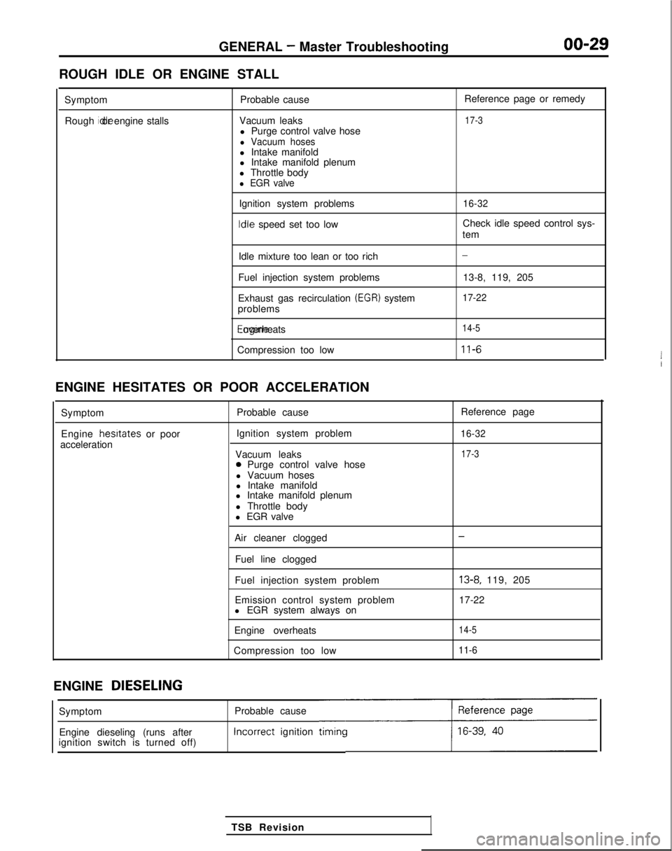
ROUGH IDLE OR ENGINE STALL
SymptomRough idle or engine stalls
Probable cause
Vacuum leaks l Purge control valve hose
l Vacuum hosesl Intake manifold
l Intake manifold plenum
l Throttle body
l EGR valve
Ignition system problems Idle
speed set too low Reference page or remedy
17-3
16-32
Check idle speed control sys-
tem
Idle mixture too lean or too rich
Fuel injection system problems
Exhaust gas recirculation
(EGR) system
problems Engine overheats
Compression too low
-
13-8, 119, 205
17-22
14-5
11-6
ENGINE HESITATES OR POOR ACCELERATION
Symptom
Engine hesrtates
or poor
acceleration Probable cause
Ignition system problem
Vacuum leaks
0 Purge control valve hose
l Vacuum hoses
l Intake manifold
l Intake manifold plenum
l Throttle body
l EGR valve Reference page
16-32
17-3
Air cleaner clogged
Fuel line clogged
Fuel injection system problem
Emission control system problem
l EGR system always on
Engine overheats
Compression too low-
13-8, 119, 205
17-22
14-5
11-6
ENGINE DIESELING
Probable cause Incorrect
ignition
timincc
TSB Revision
Symptom
Engine dieseling (runs after
ignition switch is turned off)
Page 51 of 1273
11-I
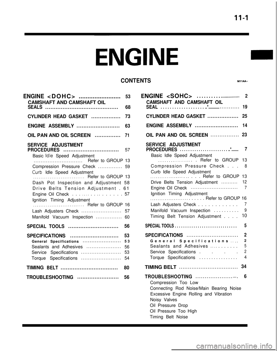
CONTENTSM11AA-
ENGINE
........................
53
CAMSHAFT AND CAMSHAFT OIL
SEALS..........................................68
CYLINDER HEAD GASKET
.................73
ENGINE ASSEMBLY
.........................63
OIL PAN AND OIL SCREEN ...............71
SERVICE ADJUSTMENT
PROCEDURES................................
57
Basic
Idle Speed Adjustment
...........................
.
Refer to GROUP 13
Compression Pressure Check ..............
59
Curb- Idle Speed Adjustment_.___..__._____....___._....Refer to GROUP 13
Dash Pot Inspection and Adjustment 58
Drive Belts Tension Adjustment . 6
1
Engine Oil Check . . .
_. _. . . _. . . . . . . 57
Ignition Timing Adjustment
__..._.__...................Refer to GROUP 16
Lash Adjusters Check ......................
.
57
Manifold Vacuum Inspection
..............
.
60
SPECIAL TOOLS.............................56
SPECIFICATIONS
............................53
General Specifications .....................
.
53
Sealants and Adhesives ....................
56
Service Specifications......................
.
53
Torque Specifications
......................
.
54
TIMINGBELT.................................80
TROUBLESHOOTING
........................56
E,NGINE
CAMSHAFT AND CAMSHAFT OIL
SEAL. . . . . . . . . . . . . . . . . . . ..*............ . . . . . . . . . .19
CYLINDER HEAD GASKET..................25
ENGINE ASSEMBLY.........................14
OIL PAN AND OIL SCREEN. . . . . . . . . . . . . . . .23
SERVICE ADJUSTMENT
PROCEDURES. . . . . . . . . . . . . . . . . . . . . . . ..*.......7
Basic Idle Speed Adjustment
. . . . . . . .._......... . Refer to GROUP 13
Compression Pressure Check . .
.
8
Curb Idle Speed Adjustment
.__................ _. . . . Refer to GROUP 13
Drive Belts Tension Adjustment .........
.
12
Engine Oil Check
..........................
.
7
Ignition Timing Adjustment
_...___............... . . . . . Refer to GROUP 16
Lash Adjusters Check . . . . . . . . . . . .
7
Manifold Vacuum Inspection . . . . . . . . . .9
Timing Belt Tension Adjustment . . . .10
SPECIAL TOOLS . . . . . . . . . . . . . . . . . . . . . . . . . . . . . \
.5
SPECIFICATIONS. . . . . . . . . . . . . . . . . . . . . . . . . . . . .2
General Specifications _. _.2
Sealants and Adhesives
._ _. . . . . . . .5
Service Specifications . . . .2
Torque Specifications . . . . . . . . . . . . . . . .4
TIMING BELT. . . . . . . . . . . . . . . . . . . . . . . . . . . . . . . . .34
TROUBLESHOOTING. . . . . . . . . . . . . . . . . . . . m.. .6
Compression Too Low
Connecting Rod Noise/Main Bearing Noise Excessive Engine Rolling and Vibration
Noisy Valves
Oil Pressure Drop
Oil Pressure Too High
Timing Belt Noise
Page 52 of 1273
11-2ENGINE
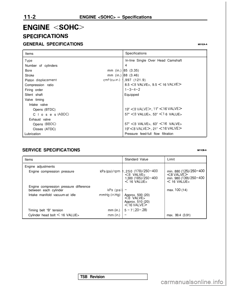
ENGINE
SPECIFICATIONS
GENERAL SPECIFICATIONSMllCA-A
ItemsType
Number of cylinders
Bore
Stroke
Piston drsplacement
Compression ratio
Firing order
Silent shaft
Valve timing
Intake valveOpens (BTDC)
Closes
(ABDC)
Exhaust valveOpens
(BBDC)
Closes (ATDC)
Lubrication Specifications
In-line Single Over Head Camshaft
4
mm (in.) 85 (3.35)
mm (in.) 88 (3.46)
cm3 (cu.in.) 1,997 (121.9)
8.5
<8 VALVE>, 9.5 < 16 VALVE>
1-3-4-2
I Equipped
19”<8VALVE>,11”<16VALVE>
57” <8 VALUE>, 53”
57”
<8 VALVE>, 63”
19” , 21” <16VALVE>
Pressure feed-full flow filtration
SERVICE SPECIFICATIONS
MllCB-A
Items Standard Value
Limit
Engine adjustments Engine compression pressure
Engine compression pressure difference
between each cylinder
Intake manifold vacuum-at idle
kPa (psi)/rpm 1,250 (178)/250-400<8 VALVE>1,300 (185)/250-400< 16 VALUE>
kPa (psi) - mmHg
(in.Hg)Approx. 500 (20)<8 VALVE>
Approx. 510 (20)
<16VALUE>
min. 880 (125)/250-400<8 VALUE>min. 980 (139)/250-400< 16 VALUE>
max.
100 (14)
Timing belt “B” tension mm (in.)
5
- 7 (.20-.28)
Cylinder head bolt
< 16 VALUE>mm(in.) -max. 99.4 (3.91)
TSB Revision
Page 56 of 1273
11-6
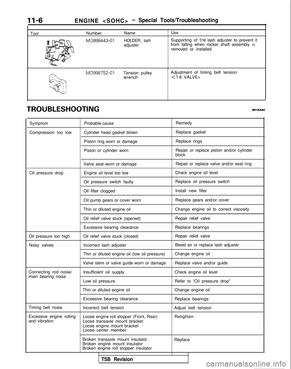
ToolENGINE
-Special Tools/Troubleshooting
Number
NameUse
M
D998443-01 HOLDER, lashSupporting of the lash adjuster to prevent it
adjuster from falling when rocker shaft assembly
IS
removed or installed MD998752-01
Tension pulley Adjustment of timing belt tension
wrench
TROUBLESHOOTINGMHEAAK
Symptom
Compression too low Probable cause
Cylinder head gasket blown Piston ring worn or damage
Piston or cylinder worn Remedy
Replace gasket
Replace rings
Repair or replace piston and/or cylinder
block
Valve seat worn or damage Repair or replace valve and/or seat ring
Oil pressure drop Engine oil level too low Check engine oil level
Oil pressure switch faulty Replace oil pressure switch
Oil filter clogged Install new filter
Oil pump gears or cover worn Replace gears and/or cover
Thin or diluted engine oil Change engine oil to correct viscosity
Oil relief valve stuck (opened) Repair relief valve
Excessive bearing clearance Replace bearings
Oil pressure too high Oil relief valve stuck (closed) Repair relief valve
Noisy valves Incorrect lash adjuster Bleed air or replace lash adjuster
Thin or diluted engine oil (low oil pressure) Change engine oil
Valve stem or valve guide worn or damage Replace valve and/or guide
Connecting rod noise/ Insufficient oil supply Check engine oil level
main bearing noise
Low oil pressure Refer to “Oil pressure drop”
Thin or diluted engine oil Change engine oil
Excessive bearing clearance Replace bearings
Timing belt noise Incorrect belt tension Adjust belt tension
Excessive engine rolling Loose engine roll stopper (Front, Rear)
and vibration Retighten
Loose transaxle mount bracket
Loose engine mount bracket
Loose center member
Broken transaxle mount insulator
Broken engine mount insulator
Broken engine roll stopper insulator Replace
TSB Revision
Page 103 of 1273
ENGINE
s
ENGINE
SPECIFICATIONS
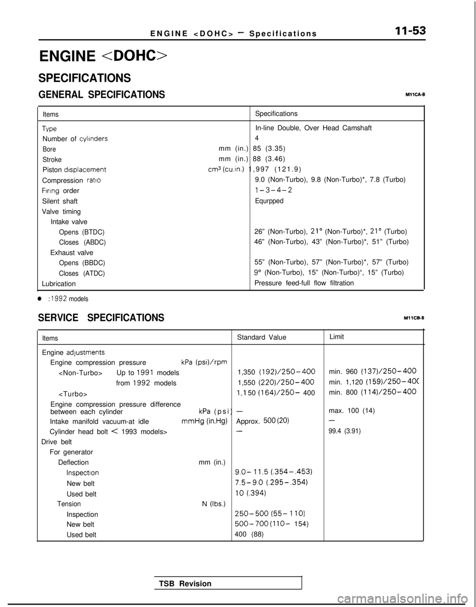
GENERAL SPECIFICATIONSMllCA-6
Items
Tvpe
Number of
cylinders
Bore
Stroke
Piston
drsplacement
Compression
ratto
Firing order
Silent shaft
Valve timing Intake valve
Opens (BTDC)
Closes (ABDC)
Exhaust valve
Opens (BBDC)
Closes (ATDC)
Lubrication
l : 1992 models
Specifications
In-line Double, Over Head Camshaft
4
mm (in.) 85 (3.35)
mm (in.) 88 (3.46)
cm3 (cu.in.) 1,997 (121.9
)
9.0 (Non-Turbo), 9.8 (Non-Turbo)*, 7.8 (Turbo)
l-3-4-2
Equrpped
26” (Non-Turbo), 21’ (Non-Turbo)*, 21’ (Turbo)
46” (Non-Turbo), 43” (Non-Turbo)*, 51” (Turbo)
55” (Non-Turbo), 57” (Non-Turbo)*, 57” (Turbo) 9”
(Non-Turbo), 15” (Non-Turbo)“, 15” (Turbo)
Pressure feed-full flow filtration
SERVICE SPECIFICATIONSMllCB-B
ItemsStandard Value Limit
Engine
adystments
Engine compression pressurekPa (psi)/rpm
from 1992
models 1,550 (220)/250-400min. 1,120 (159)/250- 4OC
Engine compression pressure difference
between each cylinderkPa (psi) -max. 100 (14)
Intake manifold vacuum-at idle mmHg
(in.Hg)Approx. 500 (20)-
Cylinder head bolt < 1993 models>-99.4 (3.91)
Drive belt
For generator
Deflection mm (in.)
Inspectron9.0- 11.5 (.354-.453)
New belt7.5-9.0 (.295-.354)
Used belt10
f.394)
TensionN (Ibs.)
Inspection250-500 (55- 1
IO)
New belt
500-700 (1 lo- 154)
Used belt 400 (88)
TSB Revision
Page 109 of 1273
ENGINE
7 Go;;ikv position
switch
(11)Check that there is continuity between the closed throttle
position switch terminal and body.
NOTE
When there is continuity, a clearance will be created between the throttle lever and dash pot rod when the dash
pot rod is pressed lightly.
(12) When there is no continuity, lower the engine speed when the dash pot begins operation to within the standard value
tolerance. Make sure to create continuity between the
closed throttle position switch terminal and body.
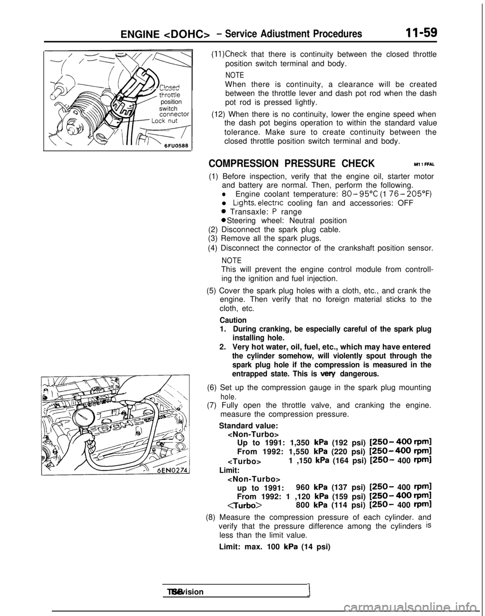
COMPRESSION PRESSURE CHECK Ml 1 FFAL
(1) Before inspection, verify that the engine oil, starter motor
and battery are normal. Then, perform the following.
lEngine coolant temperature: 80- 95°C
(1 76- 205’F)
l Lights, electnc
cooling fan and accessories: OFF
0 Transaxle: P range 0 Steering wheel: Neutral position
(2) Disconnect the spark plug cable.
(3) Remove all the spark plugs.
(4) Disconnect the connector of the crankshaft position sensor.
NOTE
This will prevent the engine control module from controll- ing the ignition and fuel injection.
(5) Cover the spark plug holes with a cloth, etc., and crank the engine. Then verify that no foreign material sticks to the
cloth, etc.
Caution
1.During cranking, be especially careful of the spark plug
installing hole.
2. Very hot water, oil, fuel, etc., which may have entered
the cylinder somehow, will violently spout through the
spark plug hole if the compression is measured in the
entrapped state. This is
vex/ dangerous.
(6) Set up the compression gauge in the spark plug mounting
hole.
(7) Fully open the throttle valve, and cranking the engine.
measure the compression pressure.
Standard value:
kPa (192 psi) [250- 400 rpml
From 1992: 1,550
kPa (220 psi) [250-400 rpm]
Limit:
up to 1991: 960
kPa (137 psi) [250- 400 rpml
From 1992: 1 ,120 kPa (159 psi) [250- 400 rpml
CTurbo>
800
kPa (114 psi) [250- 400 rpml
(8) Measure the compression pressure of each cylinder. and verify that the pressure difference among the cylinders
is
less than the limit value.
Limit: max. 100
kPa (14 psi) TSB Revision
I
Page 191 of 1273
FUEL SYSTEM
VOLUME AIR FLOW SENSOR
@ ;;vonent
connector
Intake air amount
(Wsec)162451
Multipoh fuel
injection relay
Volume air flow sensor
/\2/\N
Harness side
connector
IHjhcillo)
1.10
f-i5V
Engine
control
module
MlOYFAA
J 6FU1394
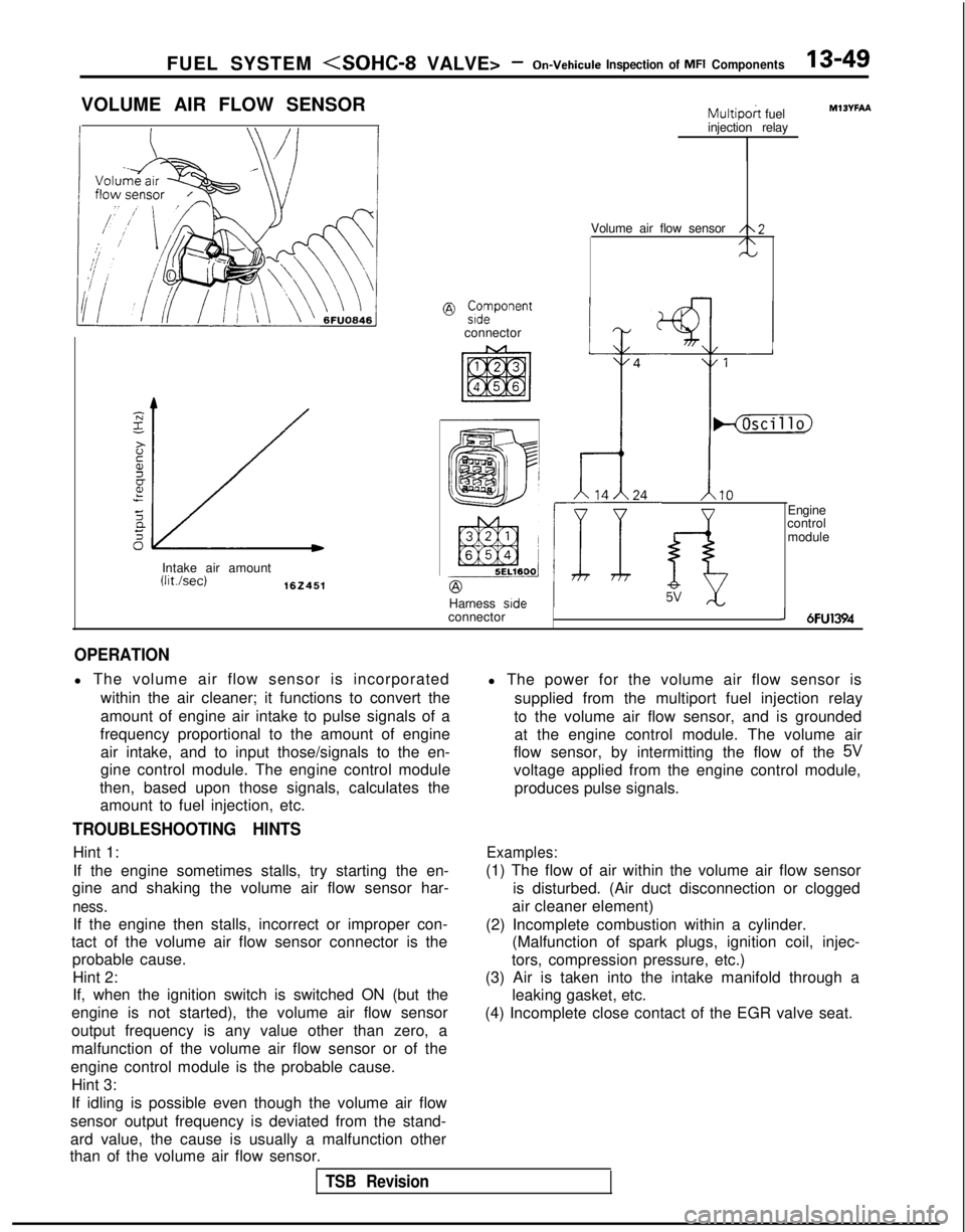
OPERATION
l The volume air flow sensor is incorporated
within the air cleaner; it functions to convert the
amount of engine air intake to pulse signals of a
frequency proportional to the amount of engine air intake, and to input those/signals to the en-
gine control module. The engine control module
then, based upon those signals, calculates the amount to fuel injection, etc.
TROUBLESHOOTING HINTS
Hint 1:
If the engine sometimes stalls, try starting the en-
gine and shaking the volume air flow sensor har-
ness.
If the engine then stalls, incorrect or improper con-
tact of the volume air flow sensor connector is the probable cause.
Hint 2:
If, when the ignition switch is switched ON (but the
engine is not started), the volume air flow sensor
output frequency is any value other than zero, a
malfunction of the volume air flow sensor or of the
engine control module is the probable cause. Hint 3:
If idling is possible even though the volume air flow
sensor output frequency is deviated from the stand-
ard value, the cause is usually a malfunction other
than of the volume air flow sensor. l The power for the volume air flow sensor is
supplied from the multiport fuel injection relay
to the volume air flow sensor, and is grounded at the engine control module. The volume air
flow sensor, by intermitting the flow of the
5V
voltage applied from the engine control module,
produces pulse signals.
Examples:
(1) The flow of air within the volume air flow sensor is disturbed. (Air duct disconnection or clogged
air cleaner element)
(2) Incomplete combustion within a cylinder. (Malfunction of spark plugs, ignition coil, injec-
tors, compression pressure, etc.)
(3) Air is taken into the intake manifold through a leaking gasket, etc.
(4) Incomplete close contact of the EGR valve seat.
TSB Revision