1989 MITSUBISHI GALANT tow
[x] Cancel search: towPage 3 of 1273
00-l
GENERAL
CONTENTS
GENERAL DATA AND SPECIFICATIONS.....23
HOWTOUSETHISMANUAL......................
3
Definition of Terms ......................................3
ExplanationofCircuitDiagrams..................7
Explanation of
ManualContents .................4
Explanation of the Troubleshooting
Guide .............................................................
6
Model
Indications .........................................3
Scope of Maintenance, Repair and
Servicing Explanations
..................................
3
Troubleshooting .............................................3
LUBRICATIONANDMAINTENANCE............
34
MAINTENANCE SERVICE............................... 39
AirCleanerElement
.....................................39
Automatic
Transaxle
.....................................43
Ball Joint and Steering Linkage Seals ........45
Brake Hoses................................................. 45
Disc Brake Pads ........................................... 44
Drive Belt (For Water Pump and
Generator) .......................................................
41
Drive
Shaft Boots .........................................45
Engine Coolant
............................................. 44
Engine Oil .....................................................
41
Engine Oil Filter ...........................................41
Exhaust System
............................................ 45
FuelHoses
...................................................39
Fuel System
.................................................39
Manual Transaxle ..........................................42
RearAxle......................................................45
Rear Drum Brake Linings and
RearWheel Cylinders
..................................44
Spark
Plugs...................................................40
Timing Belt...................................................40
MASTER
TROUBLESHOOTING.....................28
PRECAUTIONS
BEFORESERVICE................15
RECOMMENDED LUBRICANTS AND
LUBRICANT CAPACITIESTABLE..................35
SCHEDULED
MAINTENANCETABLE ...........38
SPECIAL HANDLING INSTRUCTIONS
FOR AWD MODELS
.......................................20
TABLE OF MAIN SEALANTS
AND
ADHESIVES ............................................46
TIGHTENING TORQUE
................................... 27
TOWING
ANDHOISTING ..............................17
VEHICLE
IDENTIFICATION .............................8
Chassis Number ...........................................
11
EngineModel
Stamping
...............................12
Theft Protection ............................................12
Vehicle Identification Code Chart Plate.......
8
Vehicle Identification Number List
..............8
Vehicle Identification Number Location .......
8
Vehicle Information
CodePlate...................1 1
Vehicle SafetyCertificationLabel................12
Page 19 of 1273
GENERAL - Towina and Hoisting
00-l 7
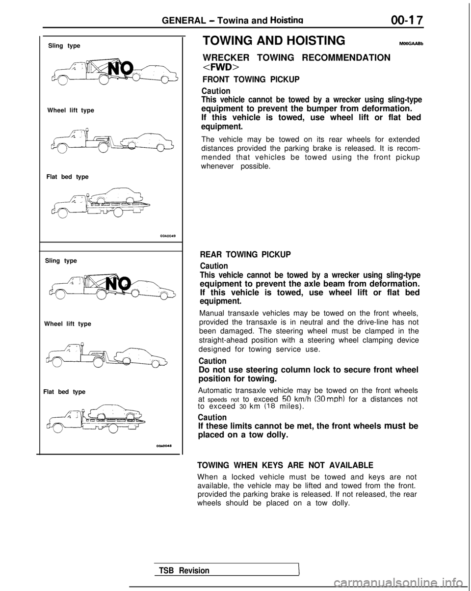
Sling type
Wheel lift type
Flat bed type
Sling type
Wheel lift type
Flat bed type TOWING AND HOISTING
WRECKER TOWING RECOMMENDATION
FRONT TOWING PICKUP
Caution
This vehicle cannot be towed by a wrecker using sling-type
equipment to prevent the bumper from deformation.
If this vehicle is towed, use wheel lift or flat bed
equipment.
The vehicle may be towed on its rear wheels for extended
distances provided the parking brake is released. It is recom-
mended that vehicles be towed using the front pickup
whenever possible.
REAR TOWING PICKUP
Caution
This vehicle cannot be towed by a wrecker using sling-type
equipment to prevent the axle beam from deformation. If this vehicle is towed, use wheel lift or flat bed
equipment.
Manual transaxle vehicles may be towed on the front wheels,
provided the transaxle is in neutral and the drive-line has not
been damaged. The steering wheel must be clamped in the
straight-ahead position with a steering wheel clamping device
designed for towing service use.
Caution
Do not use steering column lock to secure front wheel
position for towing.
Automatic transaxle vehicle may be towed on the front wheels at speeds not to exceed
50 km/h (30 mob) for a distances not
to exceed 30 km (18 miles).
Caution
If these limits cannot be met, the front wheels must be
placed on a tow dolly.
TOWING WHEN KEYS ARE NOT AVAILABLE
When a locked vehicle must be towed and keys are not available, the vehicle may be lifted and towed from the front.provided the parking brake is released. If not released, the rear
wheels should be placed on a tow dolly.
TSB Revision
Page 20 of 1273
00-l 8GENERAL - Towing and Hoisting
SAFETY PRECAUTIONS
The following precautions should be taken when towing thevehicle.
1.DO NOT LIFT OR TOW THE VEHICLE BY ATTACHING TO
OR WRAPPING AROUND THE BUMPER.
2. Any loose or protruding parts of damaged vehicle such as hoods, doors, fenders, trim, etc., should be secured prior to
moving the vehicle.
3.Operator should refrain from going under a vehicle while it
is lifted by the towing equipment, unless the vehicle in
adequately supported by satefy stands.
4. Never allow passengers to ride in a towed vehicle. 5. State and local rules and regulations must be followed when towing a vehicle.
Refer to the section “Special Handling Instructions for AWD
Models”.
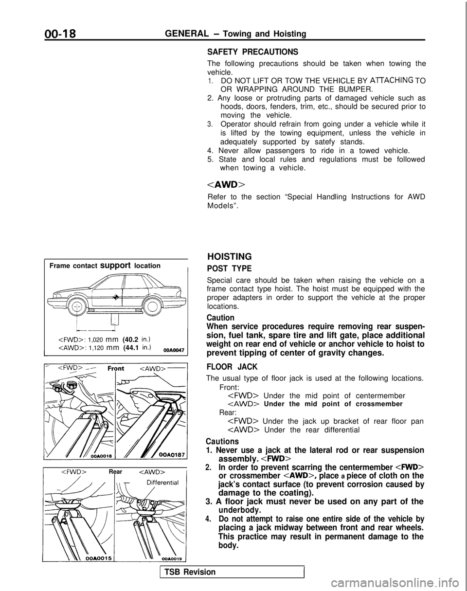
Frame contact support location
I
HOISTING
POST TYPE
Special care should be taken when raising the vehicle on a
frame contact type hoist. The hoist must be equipped with the
proper adapters in order to support the vehicle at the proper
locations.
Caution
When service procedures require removing rear suspen-
sion, fuel tank, spare tire and lift gate, place additional
weight on rear end of vehicle or anchor vehicle to hoist to
prevent tipping of center of gravity changes.
FLOOR JACK
The usual type of floor jack is used at the following locations.
Front:
tAWD> Under the mid point of crossmember
Rear:
Cautions
1. Never use a jack at the lateral rod or rear suspension
assembly.
2.In order to prevent scarring the centermember
or crossmember
place a piece of cloth on the
jack’s contact surface (to prevent corrosion caused by
damage to the coating).
3. A floor jack must never be used on any part of the
underbody.
4.Do not attempt to raise one entire side of the vehicle by
placing a jack midway between front and rear wheels.
This practice may result in permanent damage to the
body.
TSB RevisionI
Page 21 of 1273
GENERAL - Towing and Hoisting
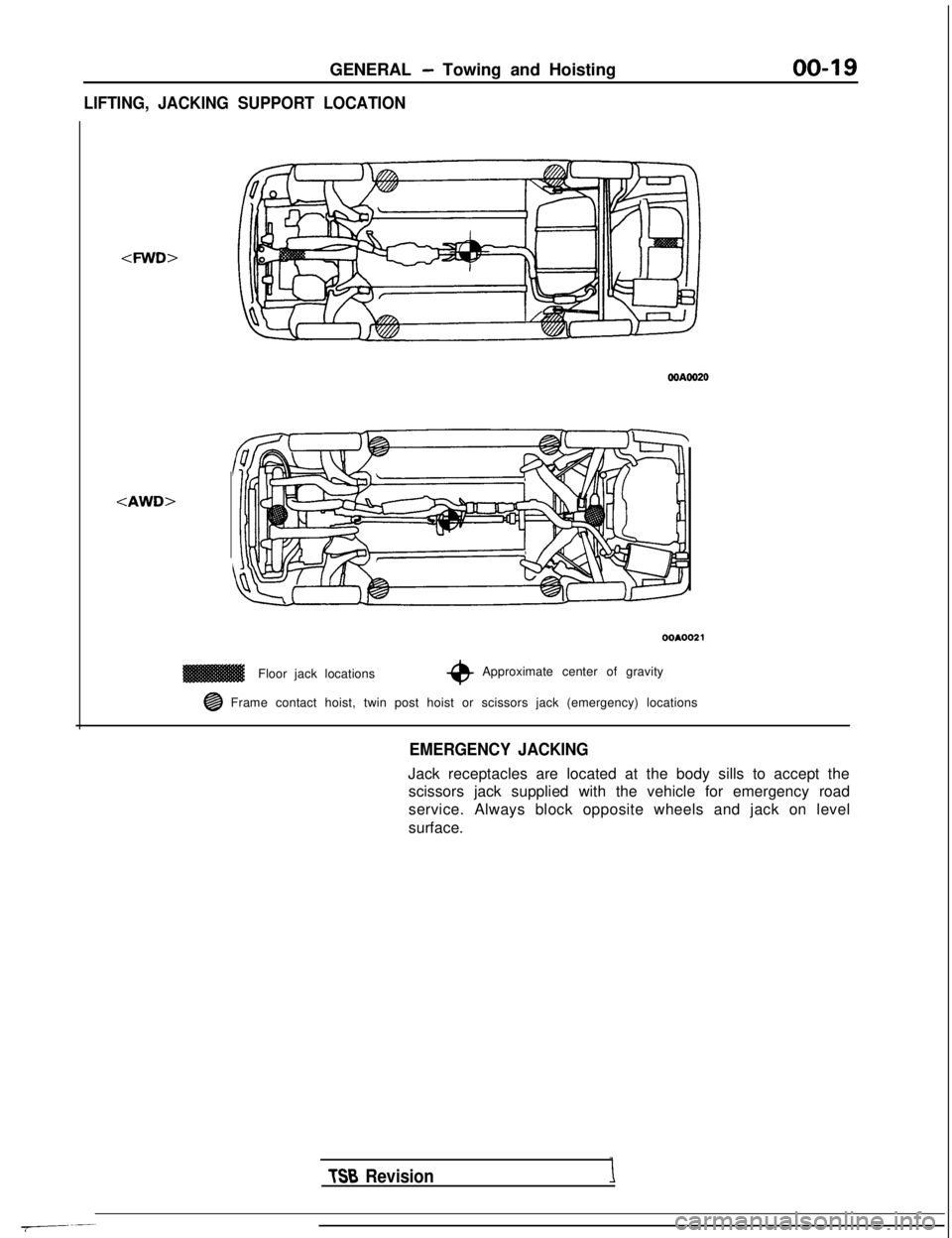
LIFTING, JACKING SUPPORT LOCATION
00-19
WA0020
00A0021
Floor jack locations-eApproximate center of gravity
@ Frame contact hoist, twin post hoist or scissors jack (emergency) loc\
ations
EMERGENCY JACKING
Jack receptacles are located at the body sills to accept the
scissors jack supplied with the vehicle for emergency road
service. Always block opposite wheels and jack on level
surface.
TSB Revision
Page 22 of 1273
00-20GENERAL - Special Handling Instructions for AWD Models
SPECIAL HANDLING INSTRUCTIONS
FOR AWD MODELS
TOWIN
G
MomMA
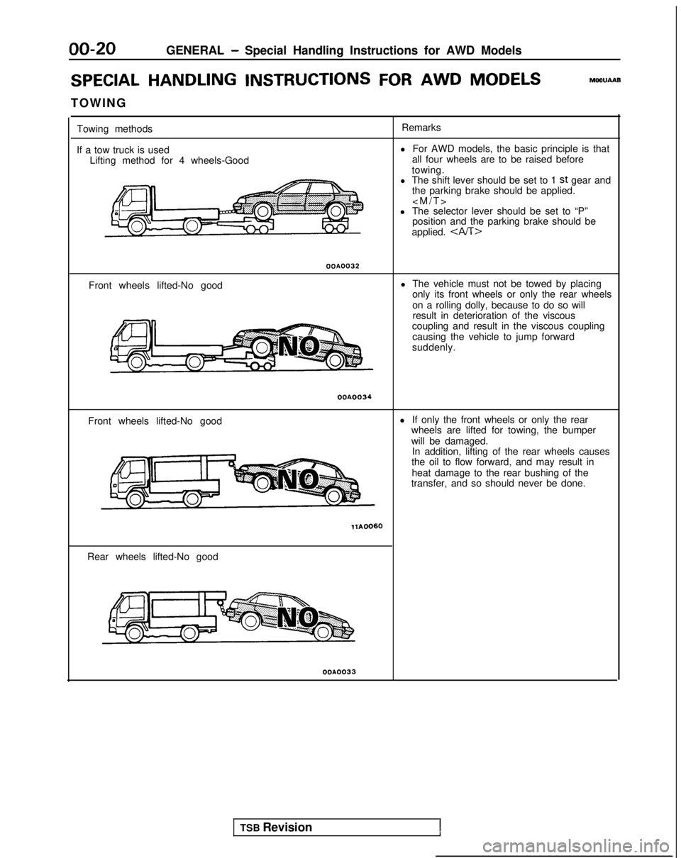
Towing methods
If a tow truck is used Lifting method for 4 wheels-Good Remarks
l For AWD models, the basic principle is that
all four wheels are to be raised before
towing.
l The shift lever should be set to 1
st gear and
the parking brake should be applied.
l The selector lever should be set to “P” position and the parking brake should be
applied.
OOA0032
Front wheels lifted-No good l The vehicle must not be towed by placing
only its front wheels or only the rear wheels
on a rolling dolly, because to do so willresult in deterioration of the viscous
coupling and result in the viscous coupling
causing the vehicle to jump forward
suddenly.
OOA0034
Front wheels lifted-No good l
If only the front wheels or only the rear
wheels are lifted for towing, the bumper
will be damaged. In addition, lifting of the rear wheels causes
the oil to flow forward, and may result in
heat damage to the rear bushing of the
transfer, and so should never be done.
Rear wheels lifted-No good
OOA0033
TSB Revision1
Page 23 of 1273
GENERAL - Special Handling Instructions for AWD Models00-21
Free roller
OOPO038
Axle stand
OOPOO37
Towino hook
Tenslon
bar
Front
eJ
Anchor plate
&-16PO209 14AO198
OOP003E
SPEEDOMETER TEST
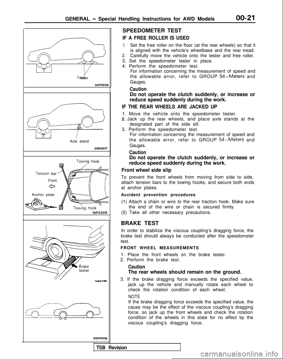
IF A FREE ROLLER IS USED
1.Set the free roller on the floor (at the rear wheels) so that it
is aligned with the vehicle’s wheelbase and the rear tread.
2.Carefully move the vehicle onto the tester and free roller.
3. Set the speedometer tester in place.
4. Perform the speedometer test. For information concerning the measurement of speed and
the allowable error, refer to GROUP
54-Meters and
Gauges.
Caution
Do not operate the clutch suddenly, or increase or
reduce speed suddenly during the work.
IF THE REAR WHEELS ARE JACKED UP
1. Move the vehicle onto the speedometer tester.
2. Jack up the rear wheels, and place axle stands at the designated part of the side sill.
3. Perform the speedometer test. For information concerning the measurement of speed and
the allowable error, refer to GROUP
54-Meters and
Gauges.
Caution
Do not operate the clutch suddenly, or increase or
reduce speed suddenly during the work.
Front wheel side slip
To prevent the front wheels from moving from side to side, attach tension bars to the towing hooks, and secure both ends
at anchor plates.
Accident prevention procedures (1) Attach a chain or wire to the rear traction hook. Make sure the end of the wire or chain is secured firmly.
(2) Take all other necessary precautions.
BRAKE TEST In order to stabilize the viscous coupling’s dragging force, the
brake test should always be conducted after the speedometer
test.
FRONT WHEEL MEASUREMENTS
1. Place the front wheels on the brake tester.
2. Perform the brake test.
Caution
The rear wheels should remain on the ground.
3. If the brake dragging force exceeds the specified value, jack up the vehicle and manually rotate each wheel tocheck the rotation condition of each wheel.
NOTE
If the brake dragging force exceeds the specified value, the
cause may be the effect of the viscous coupling’s dragging
force, so jack up the front wheels and check the rotation condition of the wheels in this state for no effect by the
viscous coupling’s dragging force.
,
TSB Revision
Page 36 of 1273
00-34GENERAL- Lubrication and Maintenance
LUBRICATION AND
MAINTE-
NANCEMOOPA-
Maintenance and lubrication service recommenda-
tions have been compiled to provide maximum protection for the vehicle owner’s investment
against all reasonable types of driving conditions. Since these conditions vary with the individual
vehicle owner’s driving habits, the area in which the
vehicle is operated and the type of driving to which
the vehicle is subjected, it is necessary to prescribe lubrication and maintenance service on a time
frequency as well as mileage interval basis.
Oils, lubricants and greases are classified and
graded according to standards recommended by the Society of Automotive Engineers (SAE), the Amer-
ican Petroleum Institute (API) and the National
Lubricating Grease Institute (NLGI).
MAINTENANCE SCHEDULES Information for service maintenance is provided
under “SCHEDULED MAINTENANCE TABLE”.
Three schedules are provided; one for “Required Maintenance”, one for “General Maintenance” and
one for “Severe Usage Service”.
The item numbers used in the “SCHEDULED MAINTENANCE TABLE” correspond to th
e
“MAINTENANCE SERVICE” section numbers.
SEVERE SERVICE
Vehicles operating under severe service conditions
will require more frequent service. Component service information
isIncluded i
n
appropriate units for vehicles operating under one or
more of the following conditrons:
1.Trailer towing or police, taxi, or
commerciai
type
operation
2. Operation of Vehicle (1) Short-trip operation at freezing temperature(engine not thoroughly warmed up)
(2) More than 50% operation in heavy city traffic during hot weather above
32°C (90°F)
(3) Extensive idling
(4) Driving in sandy areas
(5) Driving in salty areas
(6) Driving in dusty conditions
ENGINE OIL
The SAE grade number indicates the viscosity of engine oils, for example, SAE 30, which is a single
grade oil. Engine oils are also identified by a dual number, for example, SAE 1
OW-30, which Indicates
a multigrade oil.
The API classification system defines oil perform- ance in terms of engine usage. Only engine oil
designed “For Service SG” or “For Service
SGKD”,
when available, should be used. These oils contain
sufficient chemical additives to provide maximum
engine protection. Both the SAE grade and the API
designation can be found on the container.
Caution
Test results submitted to EPA have shown that
laboratory animals develop skin cancer after
prolonged contact with used engine oil. Accor-
dingly, the potential exists for humans to de-
velop a number of skin disorders, including
cancer, from such exposure to used engine oil.
Care should be taken, therefore, when changing engine oil, to minimize the amount and length of
exposure time to used engine oil on your skin.
Protective clothing and gloves, that cannot be
penetrated by oil, should be worn. The skin
should be thoroughly washed with soap and
water, or use waterless hand cleaner, to remove
any used engine oil. Do not use gasoline,
thinners, or solvents.
GEAR LUBRICANTS
The SAE grade number also indicates the viscosity of Multi-Purpose Gear Lubricants.
The API classfication
system defines gear lubricants
in terms of usage. Typically gear lubricants conform-
ing to API
GL-4 or GL-5 with a viscosity of SAE 75W-85W
are recommended for manual transaxle.
LUBRICANTS
- GREASES
Semi-solid lubricants, bear the
NLGI designation and
are further classified as grades 0, 1, 2, 3 etc.
Whenever “Chassis Lubricant” is specified,
Multi-
Purpose Grease, NLGI grade 2 should be used.
FUEL USAGE STATEMENT
Your vehicle must use unleaded gasoline only.
This vehicle has a fuel filler tube especially designed
to accept only the smaller-diameter unleaded gaso- line
dispensrng nozzle.
Caution
Using leaded gasoline in your vehicle will damage
the catalytic converter, and affect the warranty
coverage validity.
All vehicles except those with DOHC engines
Your vehicle is designed to operate on unleaded
gasoline having a minimum octane rating of 87 or
91 RON (Research Octane Number).
Vehicles equipped with DOHC engines
Your vehicle is designed to operate on premiumunleaded gasoline having a minimum
octane rating
of 91 or 95 RON (Research Octane Number).
TSB Revision
Page 41 of 1273
GENERAL - Scheduled Maintenance Table/Maintenance Service00-39
SCHEDULED MAINTENANCE UNDER SEVEiRE USAGE CONDITIONS
The maintenance items should be performed according to the following tab\
le:
Maintenance Item Service to be
Performed
IEngine Oil Change Every or
3 Months
(:z:.:a::I
Rear Drum Brake
Linings and Rear
Wheel Cylinders Inspect for Wear
and Leaks
1
Mileage Intervals Kilometers in Thousands (Miles in Thousands) Severe Usage
Conditions
More Frequently
Every 4,800 km
(3,000 miles)/xlxlx/xI I I1 Every
9,600 km (6,000 miles)
IxIxlxIxI I I>(
More Frequently1x1 I I I 1x1I I I I I I I
More Frequently
Ix1 I I I lx/
Severe usage conditions A-Driving in dusty conditions
- -B- I railer
towing or police.
taxi,
or commercial
type
operation
C-Extensive idling
D-Short trip operation at freezing temperatures (engine not thoroughly warmed up) E-Driving in sandy areas- -..F-Dnvlng In salty areas
G-More than 50% operation in heavy city trafic during
hot weather above 32°C (90°F)
MAINTENANCE SERVICE
1. FUEL SYSTEM (Tank, Lines, Connections and
Fuel Tank Filler Tube Cap) (Check for leaks)/2.
FUEL HOSES (Check for leaks or
damagekOOSnOB.
1.Check for damage or leakage in the fuel lines and con-
nections and looseness of the fuel tank filler tube cap.
2. Inspect the surface of fuel hoses for heat and mecha-
nicall damage. Hard and brittle rubber, cracking, check-
ing, tears, cuts, abrasions and excessive swelling
indicate deterioration of the rubber.
3. If the fabric casing of the rubber hose is exposed by cracks and abrasions in the fuel system, the hoses
should be changed.
3. AIR CLEANER ELEMENT (Replace)
MMlSAKH
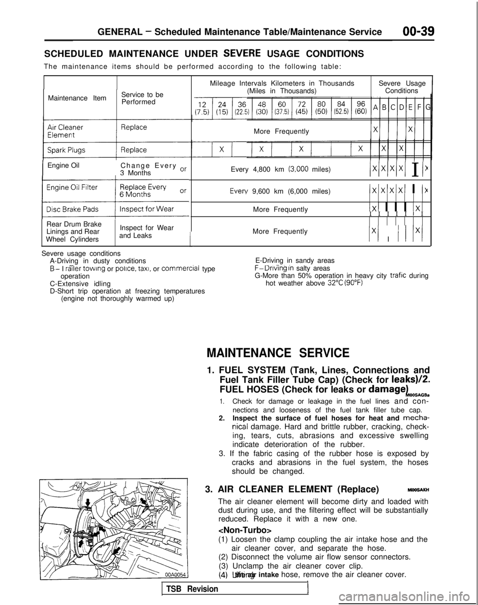
The air cleaner element will become dirty and loaded with dust during use, and the filtering effect will be substantiallyreduced. Replace it with a new one.
(1) Loosen the clamp coupling the air intake hose and the air cleaner cover, and separate the hose.
(2) Disconnect the volume air flow sensor connectors.
(3) Unclamp the air cleaner cover clip.
(4) Lifting the air intake hose, remove the air cleaner cover.
TSB Revision1