Page 46 of 1273
GENERAL -Maintenance Service
(1O)Star-t engine and allow to idle for at least two minutes.
Then, with parking brake on, move selector
fever
momentarily to each position, ending in “N” Neutral
position.
(11)Add sufficient ATF to bring fluid level to lower mark.
Recheck fluid level after transaxle is at normal Operating
temperature. Fluid level should be between upper and lower marks of
“HOT” range, Insert dipstick fully to prevent dirt from
entering transaxle.
OOA0051
11 .ENGINE
COOLANT (Change)MOOSEEAC
Check the cooling system parts, such as radiator, heater,
and oil cooler hoses, thermostat and connections for
leakage and damage.
CHANGE COOLANT
1. Remove the radiator cap.
2. Loosen the drain plug to drain the coolant.
3. Drain the coolant from the reserve tank.
4. After draining the coolant, tighten the drain plug securely.
5.Supply the coolant into the radiator until it is filled up to
its filler neck.
6. Supply the coolant into the reserve tank.
7. After warming the engine until the thermostat opens, remove the radiator cap and check the coolant level.
8.Supply the coolant into the radiator until it is filled up to
its filler neck, and install the radiator cap securely.
9.Fill the reserve tank with coolant up to the “FULL” line.
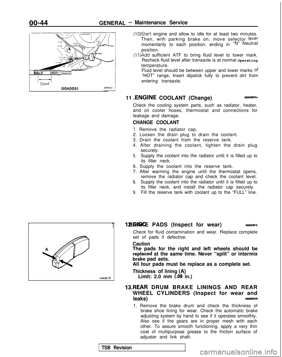
14K512
1 12.DISC BRAKE PADS (Inspect for wear) MWSBFA
Check for fluid contamination and wear. Replace complete
set of pads if defective.
Caution
The pads for the right and left wheels should be
reDlaced at the same time. Never “split” or intermix
brkke pad sets.
All four pads must be replace as a complete set.
Thickness of lining (A)
Limit: 2.0 mm (.08 in.)
13.REAR DRUM BRAKE LININGS AND REAR
WHEEL CYLINDERS (Inspect for wear and
leaks)MOOSBGB
1. Remove the brake drum and check the thickness of brake shoe lining for wear. Check the automatic brake
adjusting system by hand to see if it operates smoothly.
Also see if the gears are in proper mesh with each
other. To assure smooth functioning, apply a very thin
coat of multipurpose grease to the friction surface of
adjuster and link shaft.
TSB Revision1
Page 64 of 1273
II-14ENGINE - Ennine AssemblvENGINE
ASSEMBLY
(8 VALVE>
REMOVAL AND INSTALLATION
Pre-removal Operationl Eliminating fuel pressure in fuel line
(Refer to GROUP 13-On-Vehicle Inspection
of MFI Components.)
*Removal of the Hood (Refer to GROUP
42-Hood.)*Draining of the Coolant
(Refer to GROUP OO-Maintenance Service.)
*Removal of the Transaxle Assembly
(Refer to GROUP 22,
23-Transaxle.)*Removal of the Radiator(Refer to GROUP 14-Radiator.)
I IPost-installation Operation*Installation of the Radiator
(Refer to GROUP 14-Radiator.)*Installation of the Transaxle Assembly (Refer to GROUP 22, 23-Transaxle.)*Refilling of the Coolant(Refer to GROUP 00-Maintenance Servic
l Installation of the Hood
(Refer to GROUP
42-Hood.)
:e.) :1989
models>
-6
Nm-4 ft.lbs./
4-6 Nm3-4 ft.lbs.
cl990 models>
128
3-4 ftlbs. MllSA-A
<1991,1992 models>
1-6 Nm5-4 ft.lbs.
1-6 Nm1-4 ft.lbs.\
OlAO625
\,,OlA0647
1 TSB Revision
Page 67 of 1273
ENGINE -- Engine Assembly
ENGINE ASSEMBLY
REMOVAL AND INSTALLATION
II-17
Pre-removal Operation@Eliminating Fuel Pressure in Fuel Line (Refer to GROUP 13-Service Adjustment Proce-
dures.)
l Removal of the Hood
(Refer to GROUP
42-Hood.)l Draining of the Engine Coolant
(Refer to GROUP 00-Maintenance Service)
l Removal of the Transaxle (Refer to GROUP
22,23-Transaxle.)l Removal of the Radiator(Refer to GROUP 14-Radiator.)
Fuel rail
603AOO70
Engine oil
Post-installation Operationl Installation of the Radiator (Refer to GROUP 14-Radiator.)l Installation of the Transaxle(Refer to GROUP 22, 23-Transaxle.)l Refilling of the Engine Coolant
(Refer to GROUP 00-Maintenance Service.)
l Installation of the Hood (Refer to GROUP
42-Hood.)
4-6 Nm3-F ft.lbs.
I6m
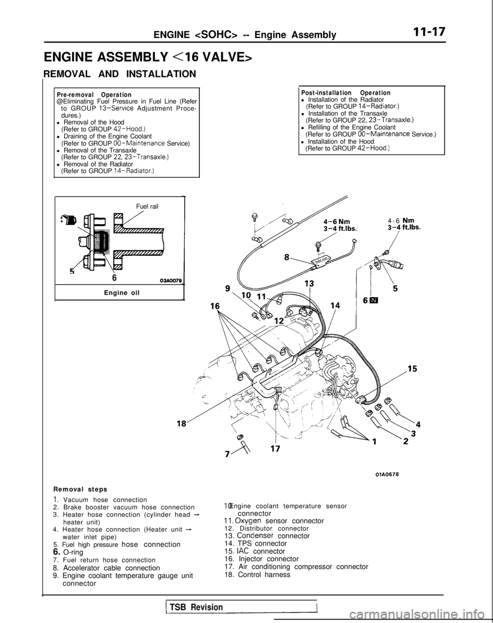
Removal steps
1. Vacuum hose connection
2. Brake booster vacuum hose connection
3. Heater hose connection (cylinder head
-heater unit)
4. Heater hose connection (Heater unit +water inlet pipe)
5. Fuel high pressure hose connection
6. O-ring
7. Fuel return hose connection
8. Accelerator cable connection
9. Engine coolant temperature gauge unit connector
OlA0676 10. Engine coolant temperature sensor
connector
II. Oxyqen
sensor connector
12. Distributor connector
13. Condenser
connector
14. TPS connector
15.
IAC connector
16. Injector connector
17. Air conditioning compressor connector
18. Control harness
1 TSBRevisionI
Page 76 of 1273
Cyl1n&r’ ;;(oozhead
Sealant: 3M
ATD Part No.8660
or equivalent 5-7
Nm4-5 ft.lbs 90-100
Nm65-72 ftlbs.
40-50 Nm /29 - 36 ft.lbs.
30-40 Nm22- 29
ftlbs.
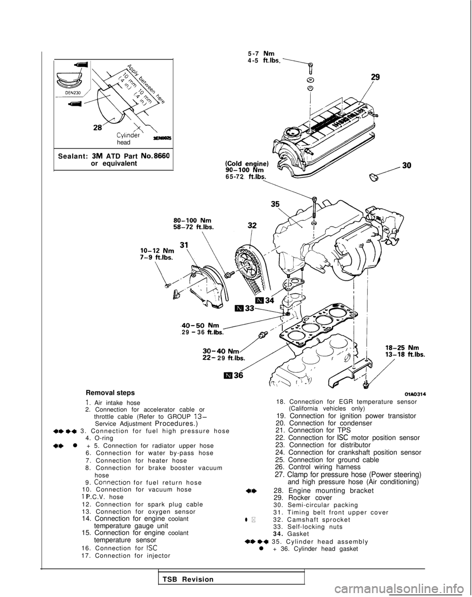
Removal steps
I. Air intake hose
2. Connection for accelerator cable or
throttle cable (Refer to GROUP
13-Service Adjustment Procedures.)+e +a 3. Connection for fuel high pressure hos
e
4. O-ring
+e l + 5. Connection for radiator upper hose
6. Connection for water by-pass hose
7. Connection for heater hose
8. Connection for brake booster vacuum
hose
9.
Connectron for fuel return hos
e
10. Connection for vacuum hose 11. P.C.V. hose
12. Connection for spark plug cable
13. Connection for oxygen sensor
14. Connection for engine coolant temperature gauge unit
15. Connection for engine coolant
temperature sensor
16. Connection for
ISC17. Connection for injector
olAo314
l *
18. Connection for EGR temperature sensor (California vehicles only)
19. Connection for ignition power transistor
20. Connection for condenser
21. Connection for TPS
22. Connection for
ISC motor position sensor
23. Connection for distributor
24. Connection for crankshaft position sensor
25. Connection for ground cable
26. Control wiring harness
27. Clamp for pressure hose (Power steering)and high pressure hose (Air conditioning)
28. Engine mounting bracket
29. Rocker cover
30. Semi-circular packing
31. Timing belt front upper cover
32. Camshaft sprocket 33. Self-locking nuts
34. Gasket
+e ++ 35. Cylinder head assembl
y
l + 36. Cylinder head gasket
TSB Revision
Page 77 of 1273
ENGINE - Cylinder Head Gasket11-27
\
r
MatingC
-I
1
J-1.‘T
:-c’ 000510020
SERVICE POINTS OF REMOVALMllJBAl
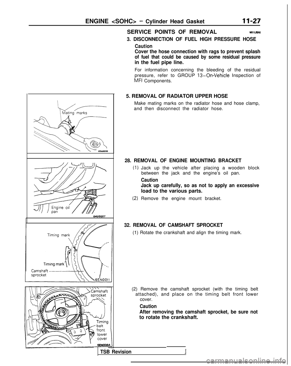
3. DISCONNECTION OF FUEL HIGH PRESSURE HOSE
Caution
Cover the hose connection with rags to prevent splash
of fuel that could be caused by some residual pressure
in the fuel pipe line.
For information concerning the bleeding of the residual
pressure, refer to GROUP
13-On-Vehicle Inspection of
MFI
Components.
5. REMOVAL OF RADIATOR UPPER HOSE Make mating marks on the radiator hose and hose clamp,
and then disconnect the radiator hose.
28. REMOVAL OF ENGINE MOUNTING BRACKET
Jack up the vehicle after placing a wooden block between the jack and the engine’s oil pan.
Caution
Jack up carefully, so as not to apply an excessive
load to the various parts.
Remove the engine mount bracket.
32. REMOVAL OF CAMSHAFT SPROCKET
(1) Rotate the crankshaft and align the timing mark.
(2) Remove the camshaft sprocket (with the timing belt attached), and place on the timing belt front lower cover.
Caution
After removing the camshaft sprocket, be sure not
to rotate the crankshaft.
TSB Revision
Page 79 of 1273
ENGINE - Cylinder Head GasketII-29
Front of engine I)Intake side
6EN094
Exhaust side
OlR0391
Fuel rail
pr&surehose\0-nng
TSB Revision
(2) Using the special tool, tighten the bolts in the order
shown in two or three steps.
5. INSTALLATION OF RADIATOR UPPER HOSE
Align the mating marks (of the radiator hose and hoseclamp), and then, while applying force in the direction of
the arrow in the illustration, seat the hose clamp to the
trace marks (on the hose) remaining from the prior connection.
Caution Be sure to install the hose clamp at the trace marks (on
the hose) remaining from the prior connection.
3. CONNECTION OF FUEL HIGH PRESSURE HOSE
When connecting the high-pressure fuel hose to the fuel rail, apply a coating of engine oil to the hose union, and in-
sert so that the O-ring is not damaged.
Page 81 of 1273
ENGINE - Winder Head Gasket
3-3.5
Nm2.2-2.5 ft.lbs. 28 Cold Engine80 Nm + 0 Nm - 20 Nm - +1/4
turn + +I/4 turn
58 ft.lbs. - 0 ftlbs. -+ 14fWbs. - +I/4 turn - +1/4 turn
/g$j?&-
- Tiff i ”.\,)
/
3
2
lo-12 Nm7-nu,L.,
40-50 Nm29-36 ftJbs.9
;;I:: k. I@@
30-40 Nm22-29 ft.lbs./18-25 Nm13-18 ft.lbs.
G
R
‘2
4
OlA0660
23. Connection for radiator upper hose
24. Connection for radiator lower hose
1)+25. Water inlet fitting, thermostat and
thermostat case assembly
26. Timing belt upper cover
4*27. Camshaft sprocket 28. Rocker cover
29. Self-locking nuts
30. Gasket
*431_ Cylinder tiead
bolt+e +432. Cylinder head assembly
l +33. Cylinder head gasket
TSB Revision
Page 113 of 1273
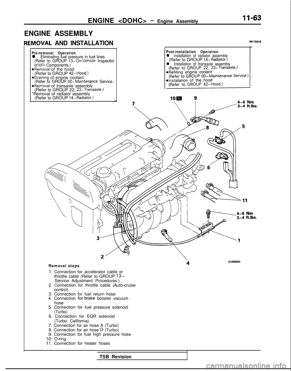
ENGINE - Engine Assembly 11-63
ENGINE ASSEMBLY
IEMOVAL AND INSTALLATION
Pre-removal Operationl Eliminating fuel pressure in fuel lines
(Refer to GROUP 13-On-Vehicle lnspectior
of MFI Components.)*Removal of the hood
(Refer to GROUP 42-Hood.)
eDraining of engine coolant(Refer to GROUP 00-Maintenance
Service.:@Removal of transaxle assembly
(Refer to GROUP 22, 23-Transaxle.)*Removal of radiator assembly
(Refer to GROUP 14-Radiator.)
MIISA-6
Post-installation Operationl installation of radiator assembly(Refer to GROUP 14-Radiator.)l Installation of transaxle assembly
Removal steps
1. Connection for accelerator cable or throttle cable (Refer to GROUP
13-Service Adjustment Procedures.)
2. Connection for throttle cable (Auto-cruise control)
3. Connection for fuel return hose
4. Connection
forbrake booster vacuum
hose
5. Connection for fuel pressure solenoid(Turbo)6. Connection for EGR solenoid (Turbo: California)
7. Connection for air hose A (Turbo) 8. Connection for air hose
D (Turbo)9. Connection for fuel high pressure hose10. O-ring11. Connection for heater hoses
TSB Revision