1989 MITSUBISHI GALANT Adjustment idle
[x] Cancel search: Adjustment idlePage 51 of 1273
11-I
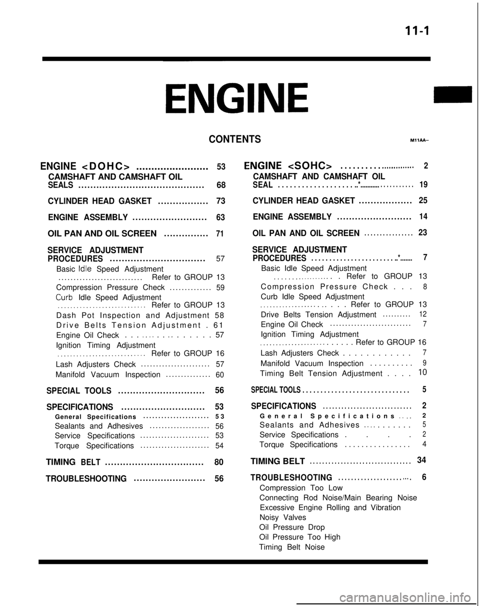
CONTENTSM11AA-
ENGINE
........................
53
CAMSHAFT AND CAMSHAFT OIL
SEALS..........................................68
CYLINDER HEAD GASKET
.................73
ENGINE ASSEMBLY
.........................63
OIL PAN AND OIL SCREEN ...............71
SERVICE ADJUSTMENT
PROCEDURES................................
57
Basic
Idle Speed Adjustment
...........................
.
Refer to GROUP 13
Compression Pressure Check ..............
59
Curb- Idle Speed Adjustment_.___..__._____....___._....Refer to GROUP 13
Dash Pot Inspection and Adjustment 58
Drive Belts Tension Adjustment . 6
1
Engine Oil Check . . .
_. _. . . _. . . . . . . 57
Ignition Timing Adjustment
__..._.__...................Refer to GROUP 16
Lash Adjusters Check ......................
.
57
Manifold Vacuum Inspection
..............
.
60
SPECIAL TOOLS.............................56
SPECIFICATIONS
............................53
General Specifications .....................
.
53
Sealants and Adhesives ....................
56
Service Specifications......................
.
53
Torque Specifications
......................
.
54
TIMINGBELT.................................80
TROUBLESHOOTING
........................56
E,NGINE
CAMSHAFT AND CAMSHAFT OIL
SEAL. . . . . . . . . . . . . . . . . . . ..*............ . . . . . . . . . .19
CYLINDER HEAD GASKET..................25
ENGINE ASSEMBLY.........................14
OIL PAN AND OIL SCREEN. . . . . . . . . . . . . . . .23
SERVICE ADJUSTMENT
PROCEDURES. . . . . . . . . . . . . . . . . . . . . . . ..*.......7
Basic Idle Speed Adjustment
. . . . . . . .._......... . Refer to GROUP 13
Compression Pressure Check . .
.
8
Curb Idle Speed Adjustment
.__................ _. . . . Refer to GROUP 13
Drive Belts Tension Adjustment .........
.
12
Engine Oil Check
..........................
.
7
Ignition Timing Adjustment
_...___............... . . . . . Refer to GROUP 16
Lash Adjusters Check . . . . . . . . . . . .
7
Manifold Vacuum Inspection . . . . . . . . . .9
Timing Belt Tension Adjustment . . . .10
SPECIAL TOOLS . . . . . . . . . . . . . . . . . . . . . . . . . . . . . \
.5
SPECIFICATIONS. . . . . . . . . . . . . . . . . . . . . . . . . . . . .2
General Specifications _. _.2
Sealants and Adhesives
._ _. . . . . . . .5
Service Specifications . . . .2
Torque Specifications . . . . . . . . . . . . . . . .4
TIMING BELT. . . . . . . . . . . . . . . . . . . . . . . . . . . . . . . . .34
TROUBLESHOOTING. . . . . . . . . . . . . . . . . . . . m.. .6
Compression Too Low
Connecting Rod Noise/Main Bearing Noise Excessive Engine Rolling and Vibration
Noisy Valves
Oil Pressure Drop
Oil Pressure Too High
Timing Belt Noise
Page 52 of 1273
11-2ENGINE
ENGINE
SPECIFICATIONS
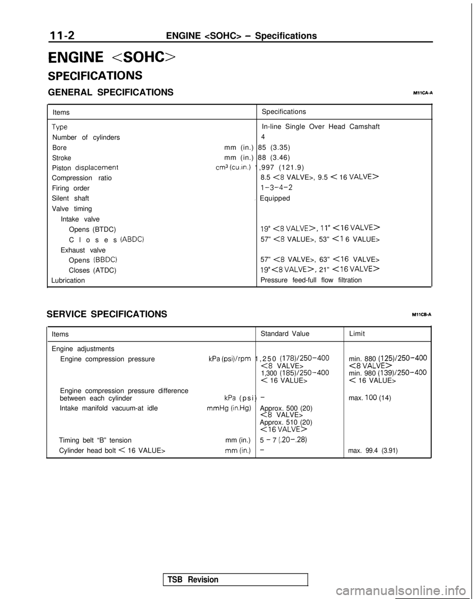
GENERAL SPECIFICATIONSMllCA-A
ItemsType
Number of cylinders
Bore
Stroke
Piston drsplacement
Compression ratio
Firing order
Silent shaft
Valve timing
Intake valveOpens (BTDC)
Closes
(ABDC)
Exhaust valveOpens
(BBDC)
Closes (ATDC)
Lubrication Specifications
In-line Single Over Head Camshaft
4
mm (in.) 85 (3.35)
mm (in.) 88 (3.46)
cm3 (cu.in.) 1,997 (121.9)
8.5
<8 VALVE>, 9.5 < 16 VALVE>
1-3-4-2
I Equipped
19”<8VALVE>,11”<16VALVE>
57” <8 VALUE>, 53”
57”
<8 VALVE>, 63”
19” , 21” <16VALVE>
Pressure feed-full flow filtration
SERVICE SPECIFICATIONS
MllCB-A
Items Standard Value
Limit
Engine adjustments Engine compression pressure
Engine compression pressure difference
between each cylinder
Intake manifold vacuum-at idle
kPa (psi)/rpm 1,250 (178)/250-400<8 VALVE>1,300 (185)/250-400< 16 VALUE>
kPa (psi) - mmHg
(in.Hg)Approx. 500 (20)<8 VALVE>
Approx. 510 (20)
<16VALUE>
min. 880 (125)/250-400<8 VALUE>min. 980 (139)/250-400< 16 VALUE>
max.
100 (14)
Timing belt “B” tension mm (in.)
5
- 7 (.20-.28)
Cylinder head bolt
< 16 VALUE>mm(in.) -max. 99.4 (3.91)
TSB Revision
Page 57 of 1273
ENGINE
OlR0340
1
SERVICE ADJUSTMENT PROCEDU$$o
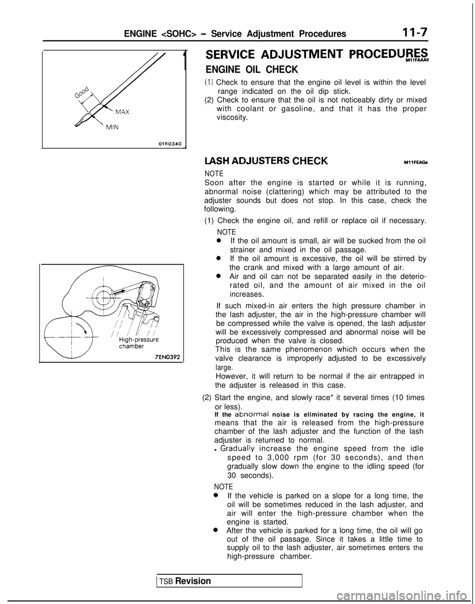
ENGINE OIL CHECK
(1) Check to ensure that the engine oil level is within the level
range indicated on the oil dip stick.
(2) Check to ensure that the oil is not noticeably dirty or mixed
with coolant or gasoline, and that it has the proper
viscosity. IASH
ACIJUSTERS CHECKMllFEAGa
NOTE
Soon after the engine is started or while it is running,
abnormal noise (clattering) which may be attributed to the
adjuster sounds but does not stop. In this case, check the
following.
(1) Check the engine oil, and refill or replace oil if necessary.
NOTE
0If the oil amount is small, air will be sucked from the oil
strainer and mixed in the oil passage.
0If the oil amount is excessive, the oil will be stirred by
the crank and mixed with a large amount of air.
0Air and oil can not be separated easily in the deterio- rated oil, and the amount of air mixed in the oil
increases.
If such mixed-in air enters the high pressure chamber in
the lash adjuster, the air in the high-pressure chamber will be compressed while the valve is opened, the lash adjuster
will be excessively compressed and abnormal noise will be produced when the valve is closed.
This is the same phenomenon which occurs when the
valve clearance is improperly adjusted to be excessively
large.
However, it will return to be normal if the air entrapped in
the adjuster is released in this case.
(2) Start the engine, and slowly race* it several times (10 times or less).
If the
ablnormal noise is eliminated by racing the engine, it
means that the air is released from the high-pressure
chamber of the lash adjuster and the function of the lash
adjuster is returned to normal.
l
Graclually increase the engine speed from the idle
speed to 3,000 rpm (for 30 seconds), and then
gradually slow down the engine to the idling speed (for
30 seconds).
NOTE 0
If the vehicle is parked on a slope for a long time, the
oil will be sometimes reduced in the lash adjuster, and
air will enter the high-pressure chamber when the
engine is started. 0
After the vehicle is parked for a long time, the oil will go
out of the oil passage. Since it takes a little time to
supply oil to the lash adjuster, air sometimes enters the
high-pressure chamber.
1 TSB Revision
Page 60 of 1273
II-IOENGINE
(3) Remove the PCV hose from the PCV valve and attach a
vacuum gauge.
(4) Check that the negative pressure at the intake manifold
during idle revolution is normal.
Standard value:
(8 VALVE>Approx. 500 mmHg (20 in.Hg)
<16VALVE>Approx. 510 mmHg (20 in.Hg)
(5) If outside the standard value, isolate the cause by referring
to the following table and repair the fault.
Symptom
CauseRemed
y
l The vacuum gauge reading is less than l Ignition timing is retarded.l Adjust the ignition timing.
standard value, but the pointer is
stable.
l The vacuum gauge pointer swings l The gas mixture is excessivelyl Check
Multiport Fuel Injection
slowly.rich.system.
l The vacuum gauge pointer drops irre-
l The gas mixture is excessively
l Check
Multiport Fuel Injectiongularly.lean.system.
l The vacuum gauge pointer drops inter-
0 Incomplete close contact of in-0 Check and repair the valve.mittently to 30 to 160
mmHg
(1.2 to take and exhaust valve seats.
6.3 in.Hg).
l The vacuum gauge pointer drops sud-l Broken cylinder head gasketl ,Replace cylinder head gasket. denly
from the normal reading to 250 mmHg
(9.8 in.Hg). then returns to
normal.
/ OlR0175
condition.
Timina mark
‘timing mark._*-
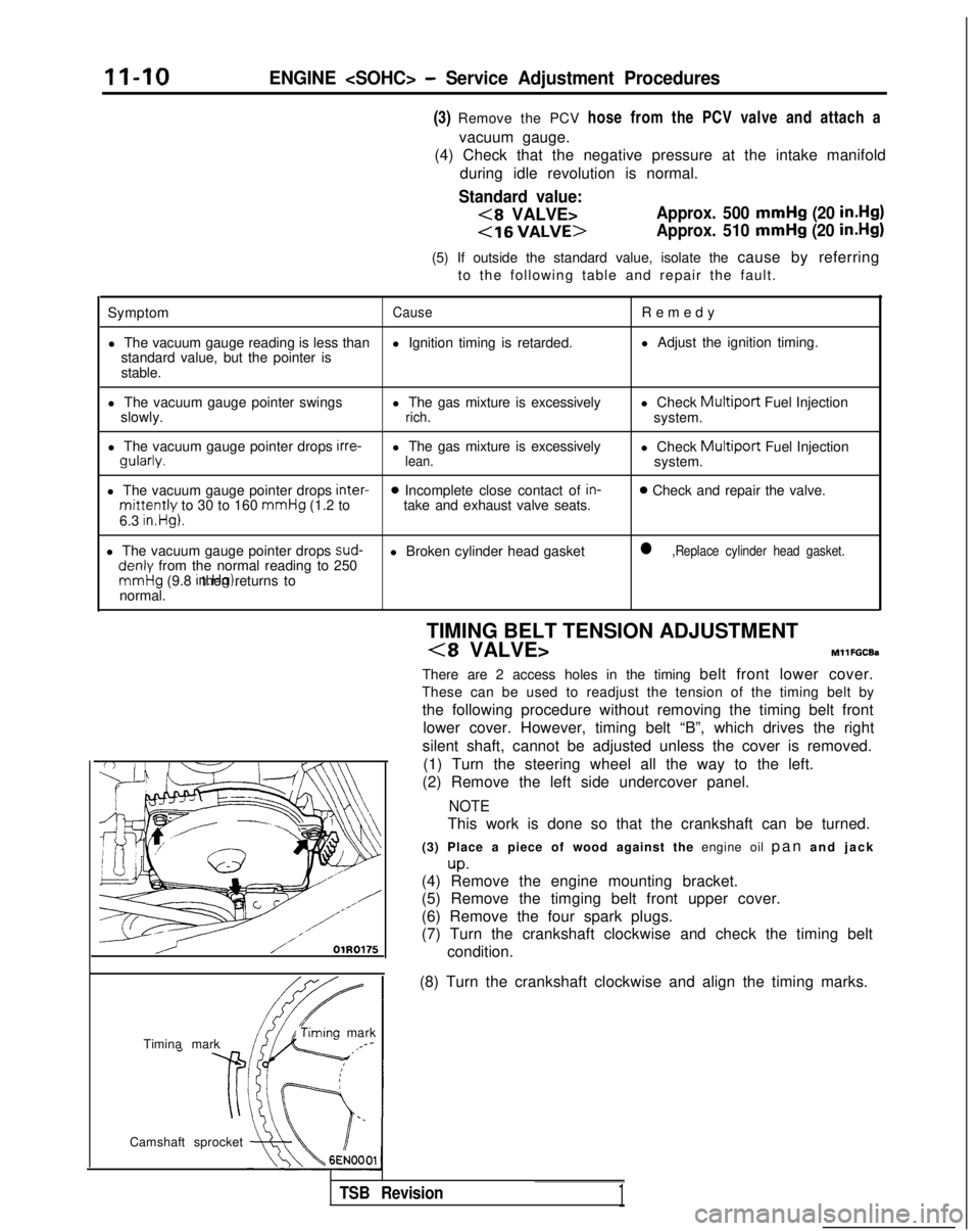
Camshaft sprocket TIMING BELT TENSION ADJUSTMENT
(8 VALVE>MllFGCEa
There are 2 access holes in the timing belt front lower cover.
These can be used to readjust the tension of the timing belt by
the following procedure without removing the timing belt front lower cover. However, timing belt “B”, which drives the right
silent shaft, cannot be adjusted unless the cover is removed. (1) Turn the steering wheel all the way to the left.
(2) Remove the left side undercover panel.
NOTE
This work is done so that the crankshaft can be turned.
(3) Place a piece of wood against the engine oil pan and jac
k
up.(4) Remove the engine mounting bracket.
(5) Remove the timging belt front upper cover.
(6) Remove the four spark plugs.
(7) Turn the crankshaft clockwise and check the timing belt
(8) Turn the crankshaft clockwise and align the timing marks.
TSB Revision1
Page 65 of 1273
ENGINE
35-4
5
25-33 35-45 Nm
25-33
ft.lbs.
24
35-45 N
m
25-33
ft.lbs.
23-2
7
250166309
I23
:l;nbs.
50-65 Nm
36-47 ft.lbs.
dv--iu wm: ’22-29 ft.lbs. \ d.(,(I3L i‘9
50-65 Nm*Cb36-47 ft.lbs.* -
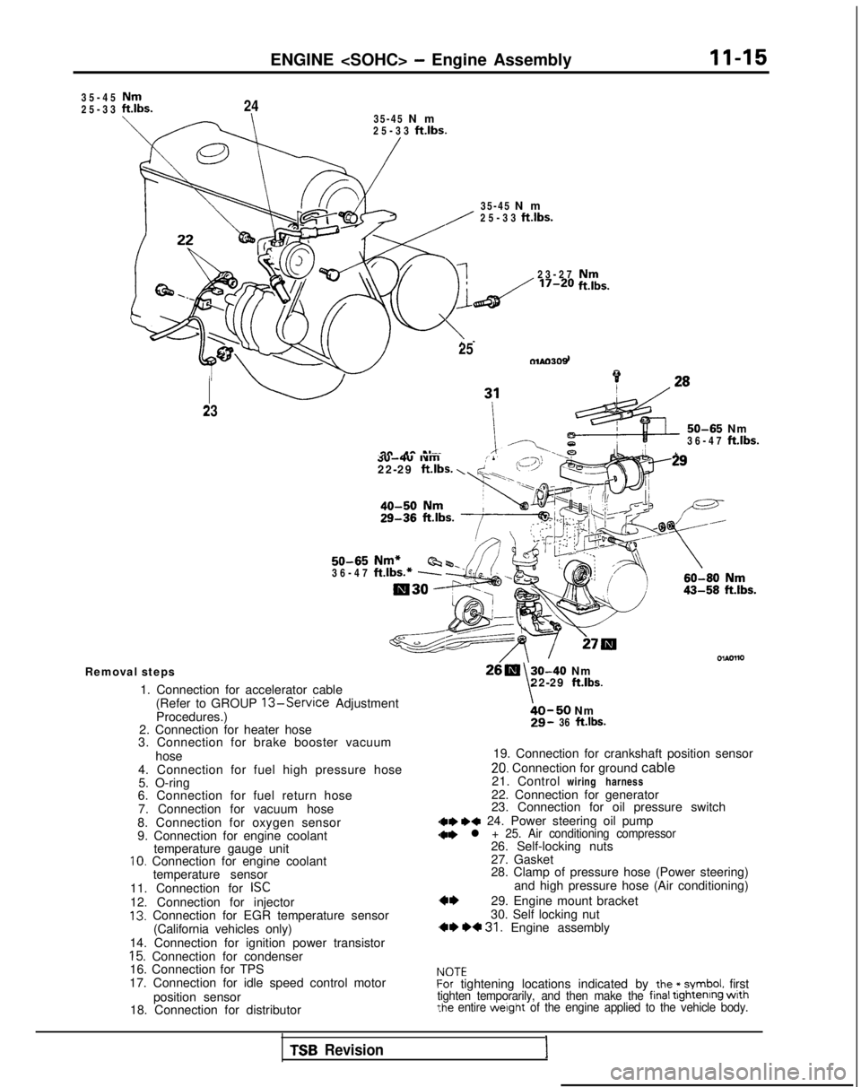
Removal steps
1. Connection for accelerator cable(Refer to GROUP
13-Service Adjustment
Procedures.)
2. Connection for heater hose
3. Connection for brake booster vacuum
hose
4. Connection for fuel high pressure hose 5. O-ring
6. Connection for fuel return hose
7. Connection for vacuum hose
8. Connection for oxygen sensor
9. Connection for engine coolant temperature gauge unit
10. Connection for engine coolant
temperature sensor
11. Connection for
ISC12. Connection for injector13. Connection for EGR temperature sensor (California vehicles only)
14. Connection for ignition power transistor
15. Connection for condenser
16. Connection for TPS
17. Connection for idle speed control motor
position sensor
18. Connection for distributor
30-40 Nm
\22-29 ft.lbs.
bO-50 Nm29- 36 ft.lbs.
19. Connection for crankshaft position sensor
20. Connection for ground cable
21. Control wiring harness
22. Connection for generator
23. Connection for oil pressure switch
dae I)* 24. Power steering oil pump
28. Clamp of pressure hose (Power steering) and high pressure hose (Air conditioning)
29. Engine mount bracket
30. Self locking nut
,** *+ 31. Engine assembly
IdOTEf-or tightening locations indicated by the * symbol. firsttighten temporarily, and then make the final tightenrng wrth?he entire werght of the engine applied to the vehicle body.
TSB Revision1
Page 93 of 1273
ENGINE
+/@Service Adjustment Procedures
24?5
20-;7 Nmio
14-20 ft.lbs.\ is\ i7
Nm50-60 Nm80-94 ft.lbs.36-43 ft.lbs.
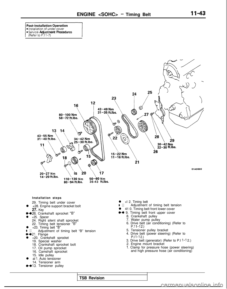
Installation steps
29. Timing belt under cover
l +28. Engine support bracket bolt
27. Keyea26. Crankshaft sprocket “6”l +25. Spacer24. Right silent shaft sprocket
22. Timing belt tensioner “B”
l +23. Timing belt
“B”l *Adjustment of timing belt “B” tension1)421. Flangel +20. Crankshaft sprocket19. Special washer
18. Crankshaft sprocket bolt
17. Oil pump sprocket
16. Camshaft sprocket
15. Idle pulley
l al
1. Auto tensioner
14. Tensioner arm 1)+13.
Tensioner pulley
ftlbs.
OlAO682
l +I 2. Timing beltl *Adjustment of timing belt tension
l 41 0. Timing belt front lower cover
I)+ 9. Timing belt front upper cover 8. Crankshaft pulley
7. Water pump pulley
6. Drive belt (air conditioning) (Refer to
P.ll-12.)5. Tensioner pulley bracket
4. Drive belt (power steering) (Refer to
P.l l-l 2.)3. Drive belt (generator) (Refer to P.l l-l 2.)
2. Engine mount bracket
I. Clamp for pressure hose (power steering) and high pressure hose (air conditioning)
TSB Revision
Page 101 of 1273
ENGINE
r
L Camshaft sprocket
Idler
pulley
/Oil pumpOlA0668
sprocket
6EN0175
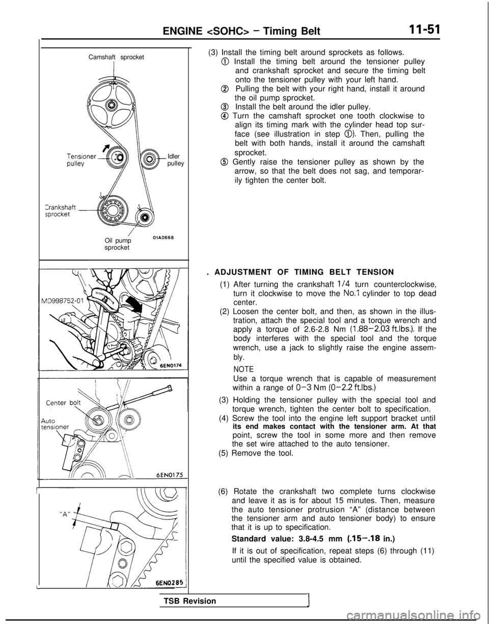
(3) Install the timing belt around sprockets as follows.
@ Install the timing belt around the tensioner pulley
and crankshaft sprocket and secure the timing belt
onto the tensioner pulley with your left hand.
@Pulling the belt with your right hand, install it around
the oil pump sprocket.
@Install the belt around the idler pulley.
@ Turn the camshaft sprocket one tooth clockwise to align its timing mark with the cylinder head top sur-
face (see illustration in step
0). Then, pulling the
belt with both hands, install it around the camshaft
sprocket.
@ Gently raise the tensioner pulley as shown by the arrow, so that the belt does not sag, and temporar-
ily tighten the center bolt.
. ADJUSTMENT OF TIMING BELT TENSION (1) After turning the crankshaft
l/4 turn counterclockwise,
turn it clockwise to move the
No.1 cylinder to top dead
center.
(2) Loosen the center bolt, and then, as shown in the illus- tration, attach the special tool and a torque wrench and
apply a torque of 2.6-2.8 Nm
(1.88-2.03 ft.lbs.). If the
body interferes with the special tool and the torque
wrench, use a jack to slightly raise the engine assem-
bly.
NOTE
Use a torque wrench that is capable of measurement
within a range of
O-3 Nm (O-2.2
ftlbs.)
(3) Holding the tensioner pulley with the special tool and
torque wrench, tighten the center bolt to specification.
(4) Screw the tool into the engine left support bracket until its end makes contact with the tensioner arm. At that
point, screw the tool in some more and then remove
the set wire attached to the auto tensioner.
(5) Remove the tool.
(6) Rotate the crankshaft two complete turns clockwise and leave it as is for about 15 minutes. Then, measure
the auto tensioner protrusion “A” (distance between
the tensioner arm and auto tensioner body) to ensure
that it is up to specification.
Standard value: 3.8-4.5 mm
(.15-.18 in.)
If it is out of specification, repeat steps (6) through (11)
until the specified value is obtained.
TSB Revision
I
Page 107 of 1273
ENGINE
OlR0340
7EN0393
1SERVICE ADJUSTMENT PROCEDUBFzo
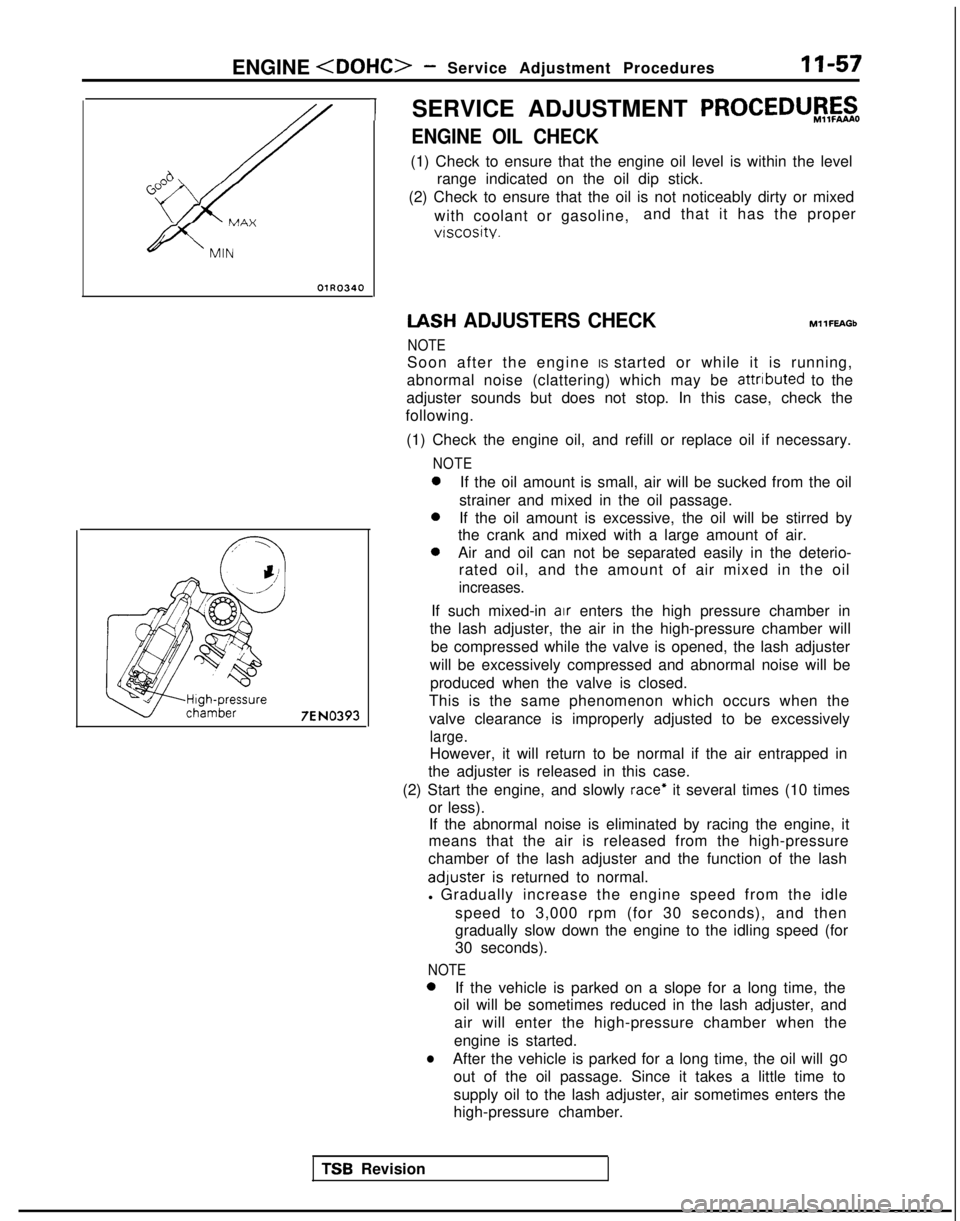
ENGINE OIL CHECK
(1) Check to ensure that the engine oil level is within the level
range indicated on the oil dip stick.
(2) Check to ensure that the oil is not noticeably dirty or mixed
with coolant or gasoline, and that it has the proper
vtscosity. IASH
ADJUSTERS CHECK
NOTE MllFEAGb
Soon after the engine IS started or while it is running,
abnormal noise (clattering) which may be attributed
to the
adjuster sounds but does not stop. In this case, check the
following.
(1) Check the engine oil, and refill or replace oil if necessary.
NOTE 0
If the oil amount is small, air will be sucked from the oil
strainer and mixed in the oil passage. 0
If the oil amount is excessive, the oil will be stirred by
the crank and mixed with a large amount of air. 0
Air and oil can not be separated easily in the deterio-
rated oil, and the amount of air mixed in the oil
increases.
If such mixed-in air enters the high pressure chamber in
the lash adjuster, the air in the high-pressure chamber will
be compressed while the valve is opened, the lash adjuster
will be excessively compressed and abnormal noise will be produced when the valve is closed.
This is the same phenomenon which occurs when the
valve clearance is improperly adjusted to be excessively
large.
However, it will return to be normal if the air entrapped in
the adjuster is released in this case.
(2) Start the engine, and slowly
race* it several times (10 times
or less). If the abnormal noise is eliminated by racing the engine, it
means that the air is released from the high-pressure
chamber of the lash adjuster and the function of the lash adluster
is returned to normal.
l Gradually increase the engine speed from the idle
speed to 3,000 rpm (for 30 seconds), and then
gradually slow down the engine to the idling speed (for
30 seconds).
NOTE 0
If the vehicle is parked on a slope for a long time, the
oil will be sometimes reduced in the lash adjuster, and
air will enter the high-pressure chamber when the
engine is started.
lAfter the vehicle is parked for a long time, the oil will go
out of the oil passage. Since it takes a little time to
supply oil to the lash adjuster, air sometimes enters the
high-pressure chamber.
TSR Revision