Page 159 of 1273
FUEL SYSTEM - Troubleshooting 13-17
\ I\-\\\\\\6FUO807
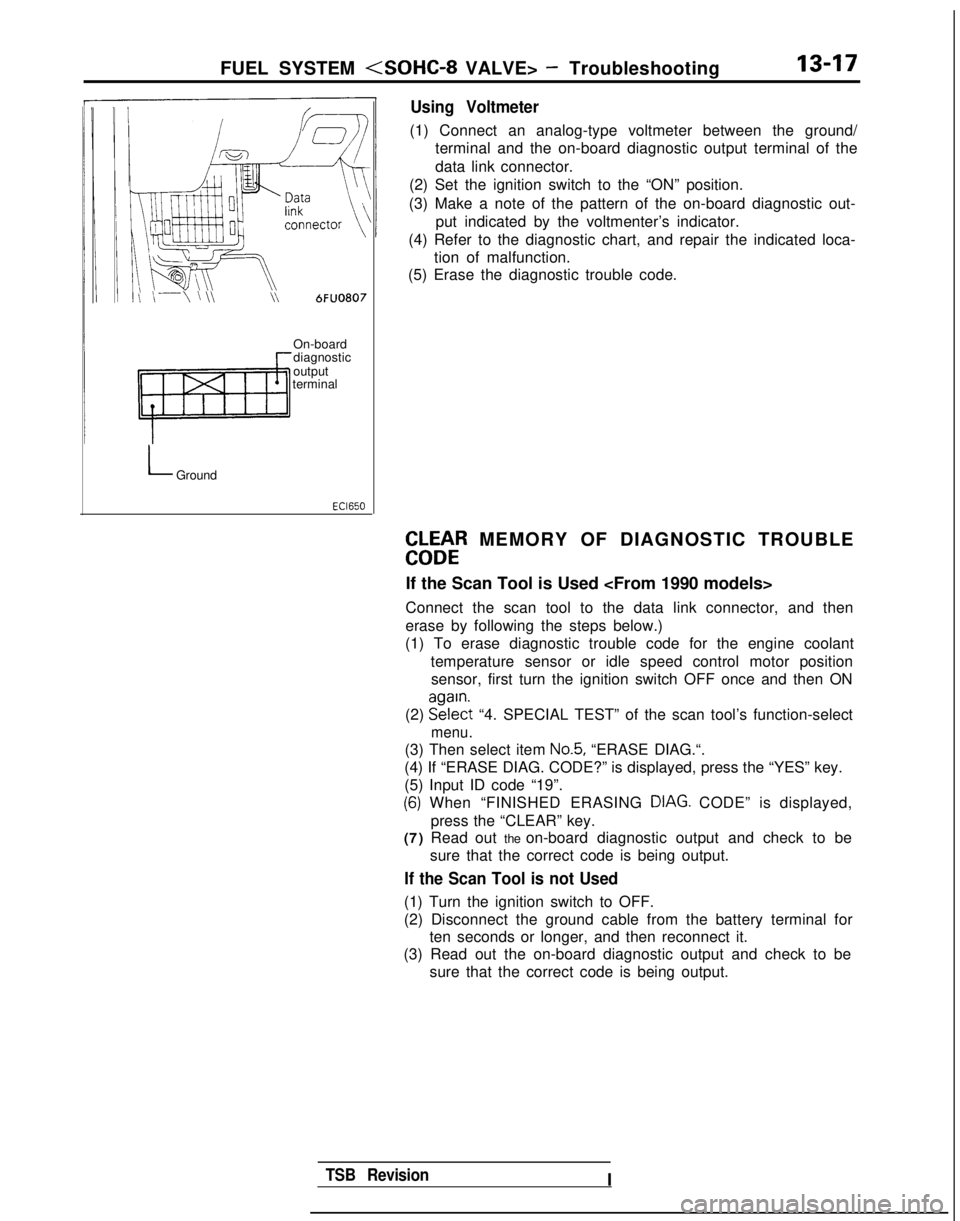
Using Voltmeter
(1) Connect an analog-type voltmeter between the ground/
terminal and the on-board diagnostic output terminal of the
data link connector.
(2) Set the ignition switch to the “ON” position.
(3) Make a note of the pattern of the on-board diagnostic out- put indicated by the voltmenter’s indicator.
(4) Refer to the diagnostic chart, and repair the indicated loca- tion of malfunction.
(5) Erase the diagnostic trouble code.
On-board
diagnostic
output
terminal
LGround
EbLbtR MEMORY OF DIAGNOSTIC TROUBLE
If the Scan Tool is Used
Connect the scan tool to the data link connector, and then
erase by following the steps below.)
(1) To erase diagnostic trouble code for the engine coolant
temperature sensor or idle speed control motor positionsensor, first turn the ignition switch OFF once and then ON
(2) EE?$t
“4. SPECIAL TEST” of the scan tool’s function-select
menu.
(3) Then select item No.5, “ERASE DIAG.“.
(4) If “ERASE DIAG. CODE?” is displayed, press the “YES” k\
ey.
(5) Input ID code “19”.
(6) When “FINISHED ERASING DIAG. CODE” is displayed,> Ipress the “CLEAR” key.
(7) Read out the on-board diagnostic output and check to be
sure that the correct code is being output.
If the Scan Tool is not Used
(1) Turn the ignition switch to OFF.
(2) Disconnect the ground cable from the battery terminal forten seconds or longer, and then reconnect it.
(3) Read out the on-board diagnostic output and check to be
sure that the correct code is being output.
TSB RevisionI
Page 184 of 1273
13-42 FUEL SYSTEM - On-Vehicule Inspection of MFI Components
(9) Switch OFF the ignition switch. (10)Disconnect
the scan tool. (11)Restart
the engine and perform a driving test, etc. to
confirm that the malfunction has been corrected.
POWER SUPPLY
Engine
control moduleu\\ v
OPERATION
l While the ignition switch is ON, battery power
supply is supplied to the engine control module,injectors, volume air flow sensor, etc.
l When the ignition switch is switched ON, cur-
rent flows from the ignition switch, via the MFI
relay coil to ground.
INSEPCTION
Using Scan Tool
relay ’
\/\/\/“
2
“3 “6
CL I 4,
Harness
side connector
Engine control module connector OlLO838
As a result, the MFI relay switch is switched ON,
and power is supplied, by way of the
MFI relay
switch, from the battery to the engine control
module.
IFunctionData displayICheck conditionsIStandard valueI
Data reading16Engine control modulepower-supply voltageIgnition switch: ONBattery positive voltage
1 TSB Revision
Page 192 of 1273
13-50 FUEL SYSTEM - On-Vehicule Inspection of MFI Components
INSPECTION
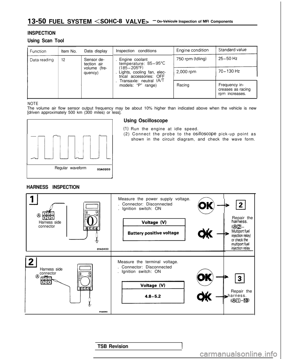
Using Scan Tool
Item No. Data display Inspection conditions
12Sensor de-
tection air
volume (fre-
quency) . Engine coolant
temperature: 85-95°C(185-205°F). Lights, cooling fan, elec-
trical accessories: OFF
. Transaxle: neutral (iVT
models: “P” range)
RacingFrequency in-
creases as racing
rpm increases.
NOTEThe volume air flow sensor output frequency may be about 10% higher than\
indicated above when the vehicle is new [driven approximately 500 km (300 miles) or less].
Regular waveform 03A0203
HARNESS INSPECTION
@
Harness sideconnector
6
0-0
~
0
=
Using Oscilloscope
(1) Run the engine at idle speed.
(2) Connect the probe to the
osilloscope pick-up point a
s
shown in the circuit diagram, and check the wave form.
Measure the power supply voltage.
. Connector: Disconnected
. Ignition switch: ON
--P
IRepair the
Harness sideconnector
Measure the terminal voltage.
. Connector: Disconnected
. Ignition switch: ON ~
0
OK’ 30
Repair the
harness
.
cm-an)
TSB Revision1
Page 194 of 1273
13-52 FUEL SYSTEM - On-Vehicule Inspection of MFI Components
Consequently, the intake air temperature sensor
terminal voltage varies in accordance with the
temperature of the intake air, becoming lower
when the temperature of the intake air in-
creases. TROUBLESHOOTING HINTS
Because the intake air temperature sensor detects
the temperature of the intake air in the air cleaner, it
indicates a temperature different than the
tempera-
ture of the outside air when the engine is running.
INSPECTION
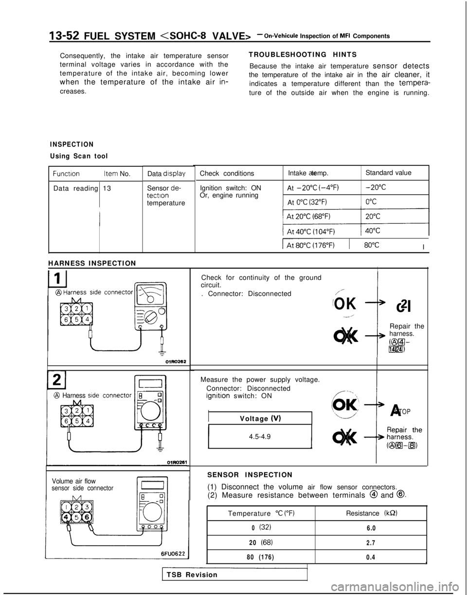
Using Scan tool
Function Item
No.
Data reading 13 Data display
Sensor de-tectlontemperature
connector
-,-S=
[
a
ry:
EQO
n
OlRO262
Check conditions
Ignition switch: ON
Or, engine running Intake air temp.
At
-20°C (-4°F)
At 0°C (32°F)
Standard value -20°C
0°C
IAt60~) I 80°CI
HARNESS INSPECTION
I
@ Harness sideconnector 8 0-0
Jill
I54
T
Volume air flowsensor side connector
Check for continuity of the ground
circuit.
. Connector: Disconnected
/-
/OKcl2
--/
Repair theharness.
@El-lT$lH)
IMeasure the power supply voltage.
Connector: Disconnected Ignition
switch: ON
IASTOPVoltage (V)
1 4.5-4.9 1
SENSOR INSPECTION
(1) Disconnect the volume air flow sensor connectors.
(2) Measure resistance between terminals @
and
@.
6FUO622
Temperature “C (“F)
0(32)
20(68)
80 (176)
Resistance (kS2)
6.0
2.7
0.4A
TSB Revision
Page 196 of 1273
13-54 FUEL SYSTEM - On-Vehicule Inspection of MFI Components
TROUBLESHOOTING HINTS Hint 1: Hint 2:
If there is a malfunction of the barometric-pressure If, during high-speed driving, there is a noticeable
sensor,
driveability of the vehicle will become worse sharp drop of the displayed pressure of th
e
barometric-rxessure sensor, check for clogging ofparticularly at hig’h altitude
.
the air cleaner.
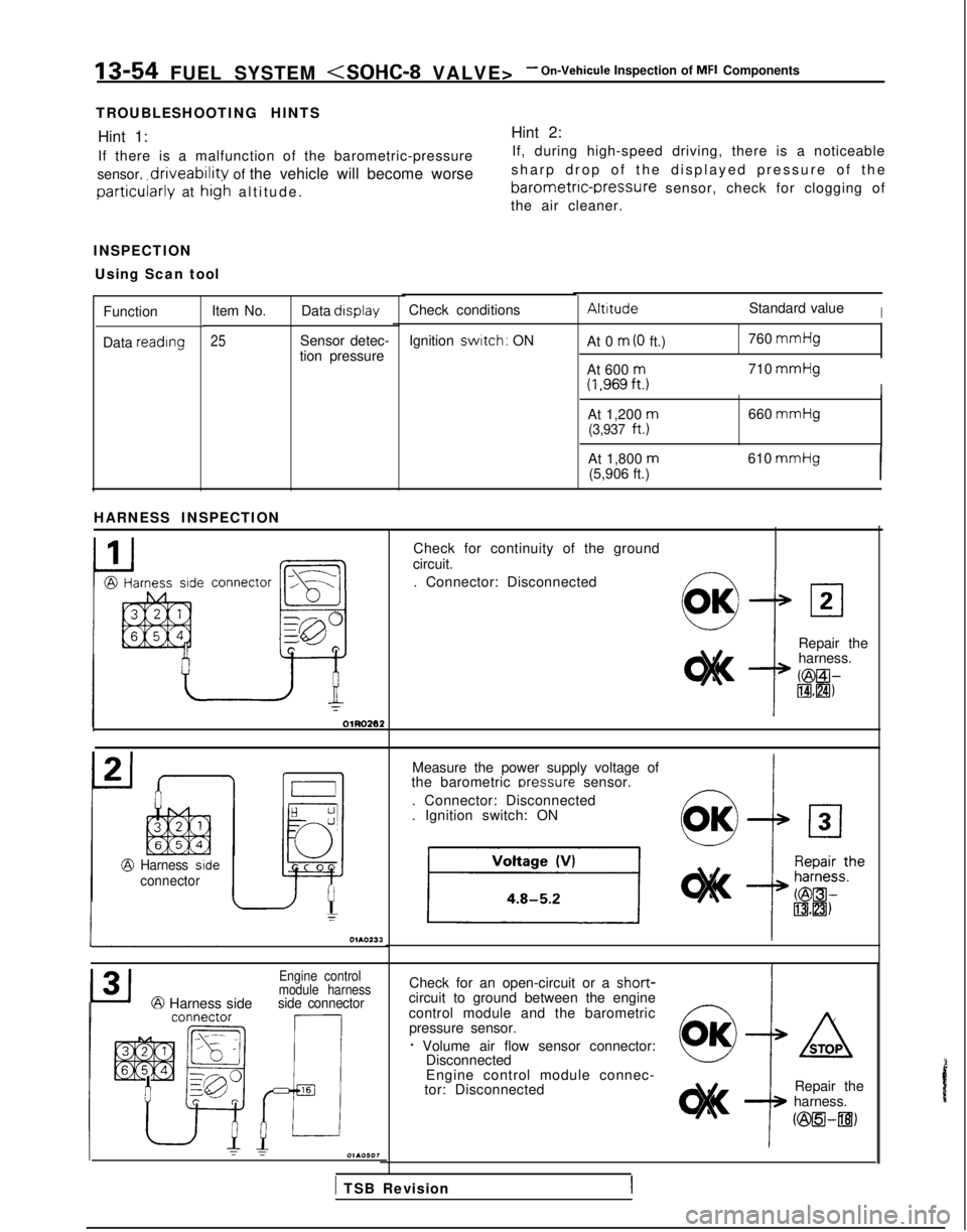
INSPECTION Using Scan tool
AltitudeStandard valueICheck conditions
Item No. Data display
25Sensor detec-
tion pressure
Function
Data reading
Ignition switch: ON
At 0 m (0 ft.) 760 mmHg
At 600
m(1,969ft.j710 mmHg
I
At 1,200 m660
mmHg(3,937
ft.)
At 1,800
m(5,906 ft.) 610 mmHgI
HARNESS INSPECTION
Check for continuity of the ground
circuit.
. Connector: Disconnected
connector
L,?
la
Fi
gg-CI
e
Repair the
harness.
KBEil-IBHZI)
Measure the power supply voltage of
the barometric oressure
sensor.
. Connector: Disconnected
. Ignition switch: ON
Harness side
connector
Check for an open-circuit or a short-circuit to ground between the engine
control module and the barometric pressure sensor.
f Volume air flow sensor connector: Disconnected
Engine control
module harness
@ Harness sideside connector
Engine control module connec-
tor: Disconnected Repair the
harness.
ozsEl-~)
1 TSB Revision
Page 198 of 1273
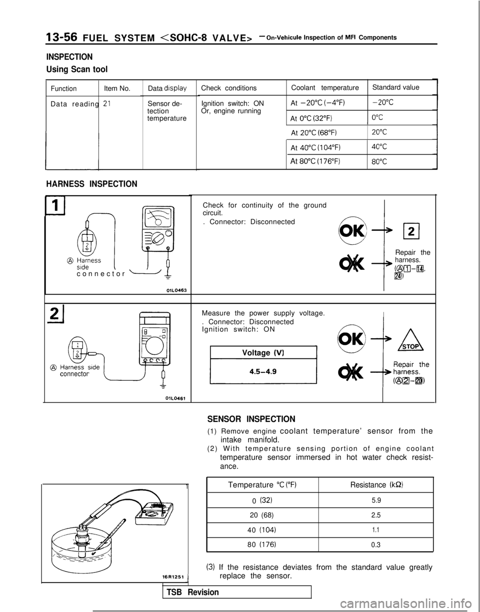
13-56 FUEL SYSTEM - On-Vehicule Inspection of MFI Components
INSPECTION
Using Scan tool
FunctionItem No.
Data reading
-*LI
Data display
Sensor de-
tection
temperature
HARNESS INSPECTION
connector OlLO461Check conditions
Ignition switch: ON
Or, engine running Coolant temperature
Standard value
At
-20°C (-4°F)-20°C
At 0°C (32°F)0°C I
At
20°C (68°F)20°C
connector - Ic
OIL0463L
-16R1251
Temperature “C (“F)Resistance (kS2)
0 (32)5.9
20 (68)2.5
40 (104)1.1
80 (176) 0.3
(3) If the resistance deviates from the standard value greatly
replace the sensor.
J
TSB Revision
At 40°C (104°F)40°C
At 80°C (176°F)80°C
1
Check for continuity of the ground
circuit.
. Connector: Disconnected
Repair the
harness.
b&XII-@.
lm
Measure the power supply voltage.I. Connector: Disconnected
Ignition switch: ONVoltage
(VI
SENSOR INSPECTION
(1) Remove engine coolant temperature’ sensor from the
intake manifold.
(2) With temperature sensing portion of engine coolan
t
temperature sensor immersed in hot water check resist-
ance.
Page 200 of 1273
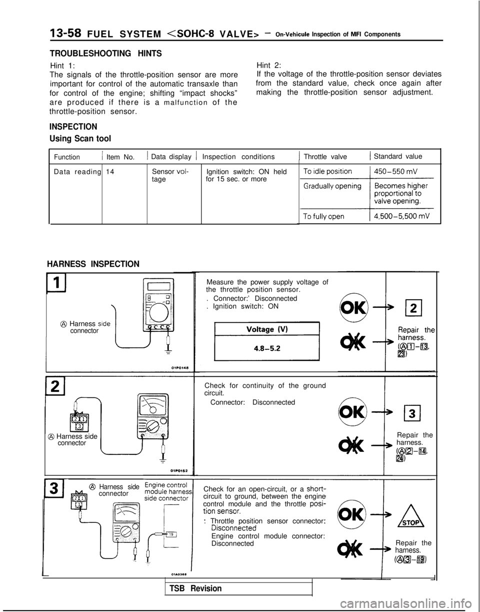
13-58 FUEL SYSTEM -On-Vehicule Inspection of MFI Components
TROUBLESHOOTING HINTS
Hint 1:Hint 2:
The signals of the throttle-position sensor are more If the voltage of the throttle-position sensor deviates
important for control of the automatic transaxle than from the standard value, check once again after
for control of the engine; shifting “impact shocks” making the throttle-position sensor adjustment.
are produced if there is a malfunction of the
throttle-position sensor.
INSPECTION
Using Scan tool
Function/ Item No.1 Data display 1 Inspection conditions1 Throttle valve1 Standard value
Data reading 14 Sensor
vol-tageIgnition switch: ON held
for 15 sec. or more
HARNESS INSPECTION
E q-0
JJ ~
@ Harness side0
connector
@ Harness sideconnector
Harness side
connector
Measure the power supply voltage of
the throttle position sensor.
. Connector:’ Disconnected
. Ignition switch: ON
Check for continuity of the ground
circuit.
Connector: Disconnected
Repair the
harness.
bZilZl-m* &I)
Check for an open-circuit, or a short-
circuit to ground, between the engine
control module and the throttle posi-
. Throttle position sensor connector: Engine control module connector:
Disconnected Repair the
harness.
Fi&TUI-mj
01103611
TSB Revision
Page 204 of 1273
13-62 FUEL SYSTEM -On-Vehicule Inspection of MFI Components
INSPECTION
Using Scan tool
FunctionItem No.
Data reading 26 Data display
Inspection conditions Switch
status Ignition
switch: ON
(Check after pumping
accelerator several times.) Throttle valve
Normal indication
To idle position
ON
Slightly openedOFF
HARNESS INSPECTION
Harness sideconnector
Y
OlR085
motor connector1 FUO480
Measure the power supply voltage of
the closed throttle position switch.
. Connector: Disconnected
. Ignition switch: ON
IVoltage (V)I
I4 or moreI
Repair theharness.
c@a-m)
SENSOR INSPECTION
(1) Disconnect the idle speed control motor connector.
(2) Check the continuity between terminal
@ and body ground.
TSB Revision
IAccelerator DedalIContinuitvI
DepressedNon-conductive (42)
Released Conductive (0. Q)
(3) If out of specification, replace the idle speed control motor
assembly.