Page 25 of 1273
GENERAL - General Data and Specifications00-23
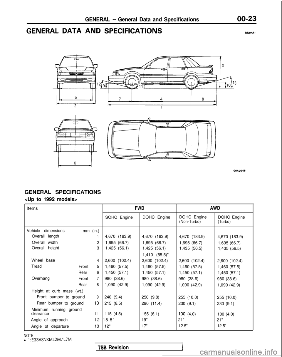
GENERAL DATA AND SPECIFICATIONSMOOHA-
3
I TT I
8
GENERAL SPECIFICATIONS
Items
FWD
AWD
SOHC EngineDOHC EngineDOHC Engine
DOHC Engine(Non-Turbo) (Turbo)
Vehicle dimensions
mm (in.)
Overall length
14,670 (183.9) 4,670 (183.9)4,670 (183.9) 4,670 (183.9)
Overall width
21,695 (66.7) 1,695 (66.7)1,695 (66.7) 1,695 (66.7)
Overall height
31,425 (56.1) 1.425 (56.1)1,435 (56.5) 1,435 (56.5)
1,410 (55.5)"
Wheel base
42,600 (102.4) 2,600 (102.4)2,600 (102.4) 2,600 (102.4)
TreadFront51,460 (57.5)1,460 (57.5)1,460 (57.5) 1,460 (57.5)
Rear61,450 (57.1)1,450 (57.1)1,450 (57.1) 1,450 (57.1)
Overhang Front
7980 (38.6)980 (38.6)980 (38.6) 980 (38.6)
Rear81,090 (42.9)1,090 (42.9)1,090 (42.9) 1,090 (42.9)
Height at curb mass (wt.) Front bumper toground
9240 (9.4)
250 (9.8)255 (10.0) 255 (10.0)
Rear bumper toground
10215 (8.5)
290 (11.4)230 (9.1) 230 (9.1)
Minimum running ground
clearance
11115 (4.5) 155 (6.1)100 (4.0)100 (4.0)
Angle of approach 12 18.5
"
19"21"21"
Angle of departure
13 12"17"12.5"
12.5"
NOTEl ’ : E33ASNXML2M/L7M
TSB RevisionI
Page 27 of 1273
GENERAL - General Data and Specifications00-25
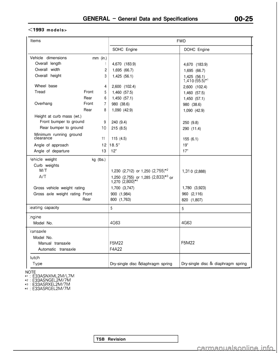
(1993 models
>
Items
FWD
SOHC Engine DOHC Engine
Vehicle dimensionsmm (in.)
Overall length14,670 (183.9)
4,670 (183.9)
Overall width21,695 (66.7)1,695 (66.7)
Overall height31,425 (56.1)1,425 (56.1) I,41
0
(55.5)*’
Wheel base4
2,600 (102.4)
2,600 (102.4)
Tread Front51,460 (57.5)1,460 (57.5)
Rear
61,450 (57.1) 1,450 (57.1)
Overhang Front7980 (38.6)980 (38.6)
Rear
81,090 (42.9) 1,090 (42.9)
Height at curb mass (wt.)
Front bumper to ground
9240 (9.4) 250 (9.8)
Rear bumper to ground10215 (8.5)290 (11.4)
Minimum running ground
clearance11115 (4.5)155 (6.1)
Angle of approach 12 18.5”19”
Angle of departure13 12”17”
lehicle weightkg (tbs.)
Curb weights
M/T
1,230 (2,712) or1,250 (2,755)*’I,31
0 (2,888)
A/T1,250 (2,755) or1,285(2,833)*3or1,270 (2,800)*4
Gross vehicle weight rating1,700 (3,747) 1,780 (3,923)
Gross axle weight rating Front900 (1,984)960 (2,116)
Rear 800 (1,763)
820 (1,807)
ieating capacity55lngine
Model No.
4G634G63 -ransaxle
Model No. Manual transaxle
F5M22 F5M22
Automatic transaxle
F4A22 lutch
Type
Dry-single disc & diaphragm spring
Dry-single disc &
diaphragm spring
d
TSB Revision
NOTE*l : E33ASNXML2MlL7M*2 : E33ASNGEL2MI7M*3 :
E33ASRXEL2M/7M*4 :
E33ASRGEL2M/7M
Page 102 of 1273
ENGINE - Timing Belt
riiis;;o;~~@
1 ip I-----$ j ggoner
~
I :
1
llAO104
1lAOlOS
II, /K. I . I
6x50
(.24x1.97)6x20(.24x.78)
6x22(.24x.87,
6x18(.24x.71)
6x251.24x.98)6x18(.24x.71)
OlAO666
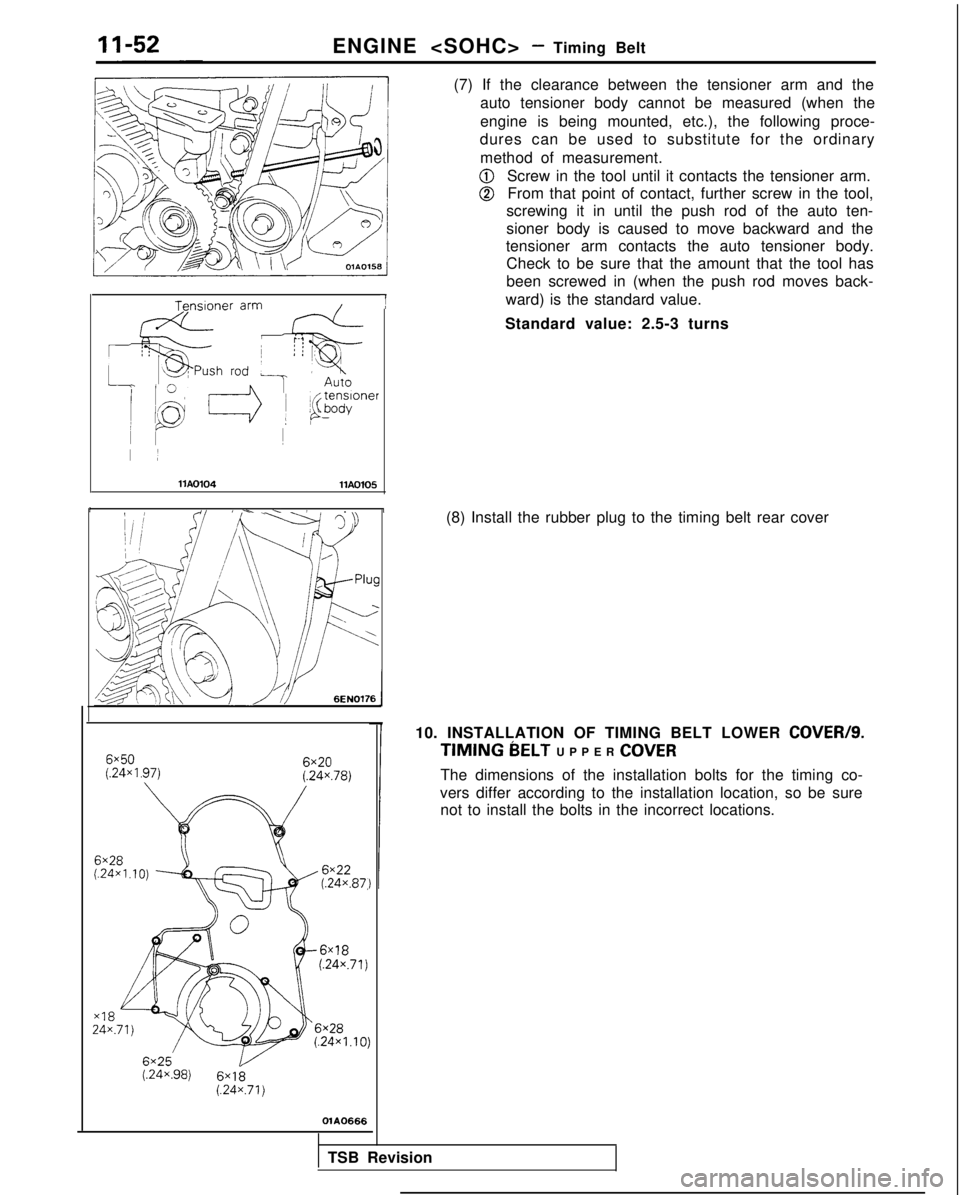
(7) If the clearance between the tensioner arm and the
auto tensioner body cannot be measured (when the
engine is being mounted, etc.), the following proce-
dures can be used to substitute for the ordinary
method of measurement.
@Screw in the tool until it contacts the tensioner arm.
@From that point of contact, further screw in the tool,
screwing it in until the push rod of the auto ten-
sioner body is caused to move backward and the
tensioner arm contacts the auto tensioner body. Check to be sure that the amount that the tool has
been screwed in (when the push rod moves back-
ward) is the standard value.
Standard value: 2.5-3 turns
(8) Install the rubber plug to the timing belt rear cover
10. INSTALLATION OF TIMING BELT LOWER COVER/S.
TIMING MELT UPPER
COVER
The dimensions of the installation bolts for the timing co-
vers differ according to the installation location, so be sure not to install the bolts in the incorrect locations.
TSB Revision
Page 142 of 1273
(8) Install the rubber plug to the timing belt rear cover.
ENGINE
- Timing Belt
*‘: Up to 1990 models*>. Up to 1992 models A*
B+2
C*’
Thread diameterx thread length
A: 6x
16 1.24x.63)B: 6x22
(.24?87j*‘, 6x18 (.24~.70)*~,*~C: 6x20
(.24x.79)*‘,
6x25 (.24x.98)*2,*3D: 6x28 (.24x1.10)
mm (in.)OlA0681
11. INSTALLATION OF TIMING BELT LOWER COVER/
10. TIMING BELT UPPER COVER
The dimensions of the installation bolts for the timing covers differ according to the installation location, so be
sure not to install the bolts in the incorrect locations.
1 TSB Revision
Page 870 of 1273
27-10REAR AXLE - Specifications
REAR AXLE
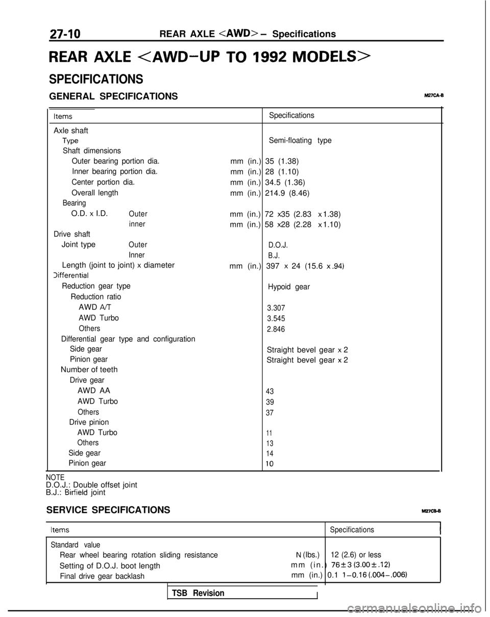
SPECIFICATIONS
GENERAL SPECIFICATIONSM27cA.B
Items
Axle shaft
Type
Shaft dimensionsOuter bearing portion dia.Inner bearing portion dia.
Center portion dia.
Overall length
Bearing
O.D. x I.D.Outer inner
Drive shaft
Joint typeOuter
Inner
Length (joint to joint) x diameter Iifferential
Reduction gear type
Reduction ratio
AWD AIT
AWD Turbo
Others
Differential gear type and configurationSide gear
Pinion gear
Number of teeth
Drive gear
AWD AA
AWD Turbo
Others
Drive pinion
AWD Turbo
Others
Side gear
Pinion gear Specifications
Semi-floating type
mm (in.) 35 (1.38)
mm (in.) 28 (1.10)
mm (in.) 34.5 (1.36)
mm (in.) 214.9 (8.46)
mm (in.) 72 x 35 (2.83 x 1.38)
mm (in.) 58 x 28 (2.28 x 1.10)
D.O.J.
B.J.
mm (in.) 397 x 24 (15.6
x .94)
Hypoid gear
3.307
3.545
2.846
Straight bevel gear x 2
Straight bevel gear
x 2
43
39
37
11
13
14
10
NOTED.O.J.: Double offset joint
B.J.: Birfield joint
SERVICE SPECIFICATIONS
Mz7cs-s
Items Specifications
Standard value
Rear wheel bearing rotation sliding resistance
Setting of D.O.J. boot length
Final drive gear backlash
TSB Revision
N (Ibs.) 12 (2.6) or less
mm (in.) 7623 (3.00rt.12)
mm (in.) 0.1 l-0.16 (.004-.006)
I
Page 1057 of 1273
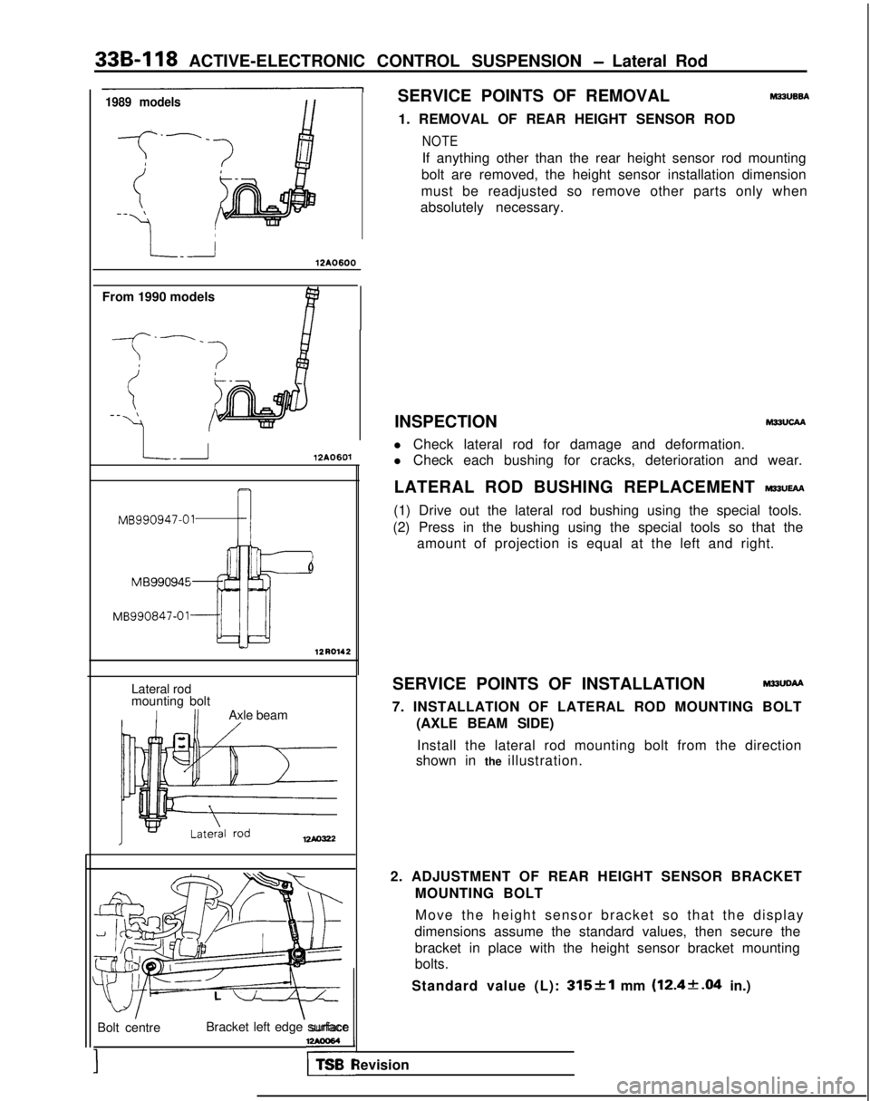
33B-118
ACTIVE-ELECTRONIC CONTROL SUSPENSION - Lateral Rod
1989 modelsSERVICE POINTS OF REMOVAL M22UB6A
1. REMOVAL OF REAR HEIGHT SENSOR ROD
NOTE
If anything other than the rear height sensor rod mounting
bolt are removed, the height sensor installation dimension
must be readjusted so remove other parts only when
absolutely necessary.
\
12A0600
From 1990 models
-f
--_
(-_ \
41
L-r12A0601
MB990947-01-4 12R0142
Lateral rod
mounting bolt
IIIAxle beam
12Ao322
Move the height sensor bracket so that the displa
y
dimensions assume the standard values, then secure the bracket in place with the height sensor bracket mounting
bolts.
Standard value (L):
315&l mm (12.4k.04 in.)
Bolt centre
;’Bracket left edge surface,
TSB Revision INSPECTION M22UCAA
l Check lateral rod for damage and deformation.
l Check each bushing for cracks, deterioration and wear.
LATERAL ROD BUSHING REPLACEMENT
WUEAA
(1) Drive out the lateral rod bushing using the special tools.
(2) Press in the bushing using the special tools so that the amount of projection is equal at the left and right.
SERVICE POINTS OF INSTALLATION M22UDAA
7. INSTALLATION OF LATERAL ROD MOUNTING BOLT (AXLE BEAM SIDE)
Install the lateral rod mounting bolt from the direction
shown in the illustration.
2. ADJUSTMENT OF REAR HEIGHT SENSOR BRACKET MOUNTING BOLT