1989 MITSUBISHI GALANT service indicator
[x] Cancel search: service indicatorPage 143 of 1273
13-1
FUEL
CONTENTSM’ISAA--
AUTO-CRUISE CONTROL SYSTEM.............
.
332
AUTO-CRUISE CONTROL ............................. 408
SERVICE ADJUSTMENT PROCEDURES .................397
Accelerator Cables
inspectron and Adjustment ........
.
398 Auto-cruise
Control System Inspection
..............397
Individual Parts Inspection ......................
401SPECfAL
TOOLS
.....................................
333
SPECIFICATIONS .................................... 332
TROUBLESHOOTING ................................. 334
Auto-cruise Control Components Location ..........368
Auto-cruise Control
Related Harnesses
..........365
Check Chart
Check Chart
Circuit Diagram ................................
371input Checking................................
.
366
On-board Diagnostic Checking ......................
361Troubleshooting Quick-reference Chart
.
334
Troubleshooting Quick-reference Chart
ENGINE CONTROL...............................
.
328
ENGINE CONTROL ..................................
330
SERVICE ADJUSTMENT PROCEDURES .................329
Accelerator Cable inspectron and Adjustment
...........329
Accelerator Switch Inspection and Adjustment ..........329
SPECIFICATIONS ....................................
328
TROUBLESHOOTlNG................................
.
328
Accelerator
Cable and Accelerator Pedal .............
.
328
FUEL SYSTEM
FUEL FILTER .........................................
327
FUEL LINE AND VAPOR LINE
.
326
FUEL LINE AND VAPOR LINE
.
324
FUEL TANK
.
322
FUELTANK
.
318
GENERAL INFORMATION ............................ 196
ON-VEHICLE INSPECTION OF MFI
COMPONENTS
......251
Air Conditioning Switch and A/C Compressor Clutch Relay .....................................
285
Barometric Pressure Sensor .................... 266
Boost Meter
311Camshaft Position Sensor ........................
.
277Closed Throttle Position Switch
.....................
.
274
Component Location .............................
251Components Inspection Pocedure
................. 255
Crankshaft Position Sensor ..................... 280EGR
Solenord
...................
.
307EGR Temperature Sensor
.............
.
288Engrne Control Module Power Ground
................
.
257
Engine Coolant Temperature Sensor ..................
268Evaporative Emission Purge Solenoid .................
.
307
Fuel Pressure Solenoid
307Fuel Pressure Test...............................
.
312
Fuel Pump ...................................... 258
Heated Oxygen Sensor ............................ 290
Idle Air Control Motor (Stepper Motor) ................
238Ignition Coil and Ignition Power Transistor .............
.
302
Ignition Switch-ST .................................. 284
Ignition Switch-ST and Park/Neutral Position Switch .....284
Injectors .......................................
295Inspection of Engine Control Module Terminal
Voltage .......................................
.
315
Intake Air Temperature Sensor .......................263
Knock Sensor
Power Steering Pressure Switch ......................
284Power Supply and Ignition Switch ...................
.
255Resistor
..............................
.
298Terminal Voltage Check Chart
......................
.
315Throttle Position Sensor
..........................
.
270Turbocharger Waste Gate Solenoid
.........
.
309 Vehicle
Speed Sensor
............................... 284
Volume Air Flow Sensor ............................
261SERVICE ADJUSTMENT PROCEDURES ...............
.
245
Basic
idle Speed Adjustment .......................
.
245
Closed Throttle Position Switch (Fixed
SAS)Adjustment ......................................
.
250
Curb
Idle Speed Inspection
..........................245Throttle Body (Throttle Valve Area) Cleaning
...........
.
248Throttle Position Sensor Adjustment
..................
.
248
SPECIALTOOLS...................................
.
204
SPECIFICATIONS ...................................
201TROUBLESHOOTING ...............................
.
205
Check Engine/Malfunction Indicator Lamp ..............205
Circuit Diagram .................................... 214
Clear Memory of Diagnostic Trouble Code .............
211Explanation and Precaution Related to Harness
Checking ......................................
.
205Explanation of Troubleshooting Procedures
............
.
205Failsafe/Back-up Functions List
.....................
.
211Fuel tank and Fuel Line
............................
.
244
Read Out Diagnostic Trouble Code ...................
211Troubleshooting Table
.............................
.
208(CONTINUED ON NEXT PAGE)
Page 144 of 1273
13-2
FUEL SYSTEM
..........
FUEL FILTER ....................................
FUEL LINE AND VAPOR LINE .....................FUELTANK....................................
.
GENERAL INFORMATION ........................
ON-VEHICLE INSPECTION OF MFI
COMPONENTS . .
Air
Conditionrng Switch and A/C CompressorClutch Relay ......
.
.............
Barometric Pressure Sensor .........
Camshaft Position Sensor ...........
Closed Throttle Position Switch ...........
Component Location .............
Components
Inspectron Procedure .......
.
Crankshaft Positron Sensor ............
EGR Solenoid
. . .3. .
115..,.113
. 109
. . 3
. . . 38
83
536961384173101EGR Temperature Sensor
.
85
Enqine Control Module Power Ground ......
.
....
45
Engine Coolant Temperature Sensor ...............
55Evaporative Emission Purge Solenord..............
.
99
Fuel Pressure ...............................
102Fuel Pump
...................................
.
46
Idle Speed Control Motor (DC Motor) ................
.
93
Idle Speed Control Motor Positron Sensor ............
.
64
lgnitron Co11 and Ignition Power Transistor .........
.
96
Ignition Switch-ST ..........................
77Ignition Switch-ST and Park/Neutral Position Switch
...78
Injectors..................................
.
90
Inspection of
Engrne Control Module Terminal
Voltage .........
.
..........................
105Intake Air Temperature Sensor ..................
.
51Oxygen Sensor
............................
.
87Power Steering Pressure Switch
..................
.
81Power Supply
.........................
.
42
Terminal Voltage Check Chart ......................
106Throttle Positron Sensor.....................
.
57Vehicle Speed Sensor
.........................
.
80
Volume Air Flow Sensor .........................
49
SERVICE ADJUSTMENT PROCEDURES .................
32
Basic
Idle Speed Adjustment ...................
.
33
Curb Idle Speed Inspection ..........................
32Throttle Body (Throttle Valve Area) Cleaning........
.
35
Throttle Positron Sensor Adjustment ................
35
SPECIAL TOOLS 7
.................
...................
SPECIFICATIONS ....................................
5
TROUBLESHOOTING .................................
8
Check Engine/Malfunction Indicator Lamp ..............
10Crrcuit Diagram.................................
.
20
Clear Memory of Diagnostic Trouble Code ............
17Explanation and Precaution Related to HarnessChecking......................................
.
9Explanation of Troubleshooting Procedures
...........
.
8
Failsafe/Back-up Functions List ....................
16Fuel Tank and Fuel Lrne.........................
.
32Read Out of Diagnostic Trouble Code
...............
.
16Troubleshooting Table
.........................
.
13
FUEL SYSTEM
116
FUEL FILTER .......................................
195
FUEL LINE AND VAPOR LINE ........................
195
FUEL TANK ........................................ 195
GENERAL INFORMATION ............................
116
ON-VEHICLE INSPECTION OF MFI
COMPONENTS
Air Conditioning Switch and A/C Compressor Clutch Relay .............................
Barometric Pressure Sensor .................
Camshaft Position Sensor ....................
Closed Throttle Position Switch ................
Component Location .......................
Components Inspectron Pocedure
..............
Crankshaft Position Sensor .................
EGR Solenoid
EGR Temperature Sensor
Engine Control Module Power Ground ..........
Engine Coolant Temperature Sensor .............
Evaporative Emission Purge Solenoid ............
Fuel Pressure Test ...........................
Fuel Pump ..................................
IAC Valve Positon Sensor
......................
Idle Air Control Motor (DC Motor) ..............
lgnrtion Coil and Ignition Power Transistor
.......
.
Ignition Switch-ST ...........................
Ignition Switch-ST and Park/Neutral Position Switch
Injectors ....................................
Inspection of Engine Control Module Terminal
Voltage .....................................
Intake Air Temperature Sensor .................
Oxygen Sensor .............................
Power Steering Pressure
Swatch..............
.
Power Supply ...............................
Terminal Voltage Check Chart ..................
Throttle Position Sensor .......................
Vehicle Speed Sensor ......................... . . . . 139
176
154
165
16013914216
7
..,_ 191177146
155
189192
147
162
184
186
171172181
192152
179
175
143
192
157
173
Volume Air Flow Sensor ...........................
.
150
SERVICE ADJUSTMENT PROCEDURES
...............
.
133
Basic Idle Speed Adjustment 133
Closed Throttle Position Switch and Throttle Position
Sensor Adjustment .................................
136Curb Idle Speed Inspection
.........................
.
133Fixed SAS Adjustment
.............................
.
138Throttle Body (Throttle Valve Area) Cleaning
...........
.
136
SPECIAL TOOLS
...................................
.
119
SPECIFICATIONS 118
.... ..............................
TROUBLESHOOTING ..................
.............
119
Check Engine/Malfunction Indicator Lamp ..............
120Circuit Diagram...................................
.
128Clear Memory of Diagnostic Trouble Code
............
.
126Explanation and Precaution Related to Harness
Checking ........................................
.
119Explanation of Troubleshooting Procedures
............
.
119Failsafe/Back-up
Fuctions List
........................
126
Fuel Tank and Fuel Line .............................
133Read Out of Diagnostic Trouble Code ................
.
126
Troubleshooting Table ..............................
123
Page 539 of 1273
AUTO-CRUISE CONTROL SYSTEM - Setice Adjustment ~m~edures13-397
i
ON
y SET
03AO258
03AO258
y SET
CGA0258
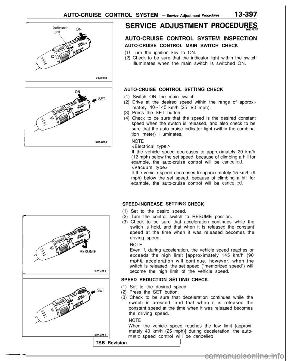
(1) Set to the desired speed.
(2) Press the SET button. (3) Check to be sure that deceleration continues while the switch is pressed, and that when it is released the
constant speed at the time when it was released becomes
the driving speed.
NOTE
When the vehicle speed reaches the low limit [approxi- mately 40 km/h (25 mph)] during deceleration, the auto-
matrc speed control will be cancelled.
TSB RevisionI
SERVICE ADJUSTMENT PROCEDU$$jF
AUTO-CRUISE CONTROL SYSTEM INSPECTION
AUTO-CRUISE CONTROL MAIN SWITCH CHECK
(I) Turn the ignition key to ON.
(2) Check to be sure that the indicator light within the switch
illuminates when the main switch is switched ON.
AUTO-CRUISE CONTROL
SETTING CHECK
(1) Switch ON the main switch.
(2) Drive at the desired speed within the range of approxi-
mately
40-145 km/h (25-90 mph).
(3) Press the SET button.
(4) Check to be sure that the speed is the desired constant speed when the switch is released, and also check to be
sure that the auto cruise indicator light (within the combina-
tion meter) illuminates.
NOTE
If the vehicle speed decreases to approximately 20 km/h
(12 mph) below the set speed, because of climbing a hill for
example, the auto-cruise control will be
cancelled.
If the vehicle speed decreases to approximately 15 km/h (9
mph) below the set speed, because of climbing a hill for
example, the auto-cruise control will be
cancelled.
SPEED-INCREASE SETl-ING
CHECK
(1) Set to the desird speed.
(2) Turn the control switch to RESUME position.
(3) Check to be sure that acceleration continues while the switch is hold, and that when it is released the constant
speed at the time when it was released becomes the
driving speed.
NOTE
Even if, during acceleration, the vehicle speed reaches or exceeds the high limit [approximately 145 km/h (90
mph)], acceleration will continue, however, when the
switch is released, the set speed (“memorized speed”) will
become the high limit of the vehicle speed.
SPEED REDUCTION
SEITING CHECK
--
Page 560 of 1273
14-8
COOLING -Service Adjustment Procedures T210863
SERVICE ADJUSTMENT PROCEDUl$t&
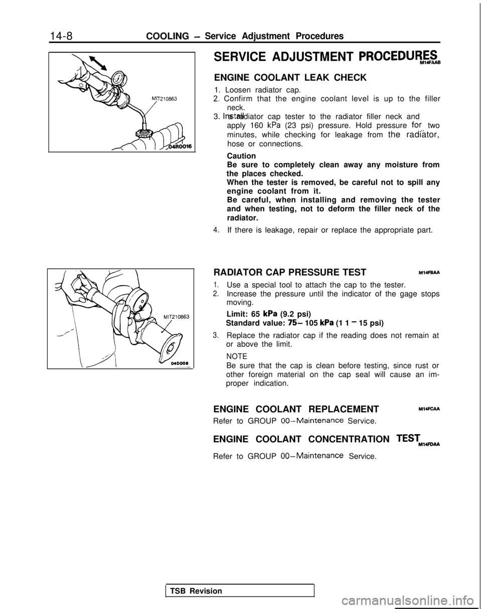
ENGINE COOLANT LEAK CHECK
1. Loosen radiator cap.
2. Confirm that the engine coolant level is up to the filler
neck.
3. Install a radiator cap tester to the radiator filler neck and
apply 160
kPa (23 psi) pressure. Hold pressure for. two
minutes, while checking for leakage from the radiator, hose or connections.
Caution
Be sure to completely clean away any moisture from
the places checked. When the tester is removed, be careful not to spill anyengine coolant from it.
Be careful, when installing and removing the tester
and when testing, not to deform the filler neck of the
radiator.
4.If there is leakage, repair or replace the appropriate part.
RADIATOR CAP PRESSURE TEST
MlOFBAA
1.Use a special tool to attach the cap to the tester.
2.Increase the pressure until the indicator of the gage stops
moving.
Limit: 65
kPa (9.2 psi)
Standard value:
75- 105 kPa (1 1 - 15 psi)
3.Replace the radiator cap if the reading does not remain at
or above the limit.
NOTE
Be sure that the cap is clean before testing, since rust or
other foreign material on the cap seal will cause an im-
proper indication.
ENGINE COOLANT REPLACEMENT
MMFCAA
Refer to GROUP 00-Maintenance Service.
ENGINE COOLANT CONCENTRATION TEST,,wti
Refer to GROUP
00-Maintenance Service.
TSB Revision
Page 789 of 1273
AUTOMATIC TRANSAXLE - Service Adjustment Procedures23-83
I:
I’
4989 models>
09A0140
6% Button pressed (while brakepedal is depressed)
c Button not pressed
0 Button pressed
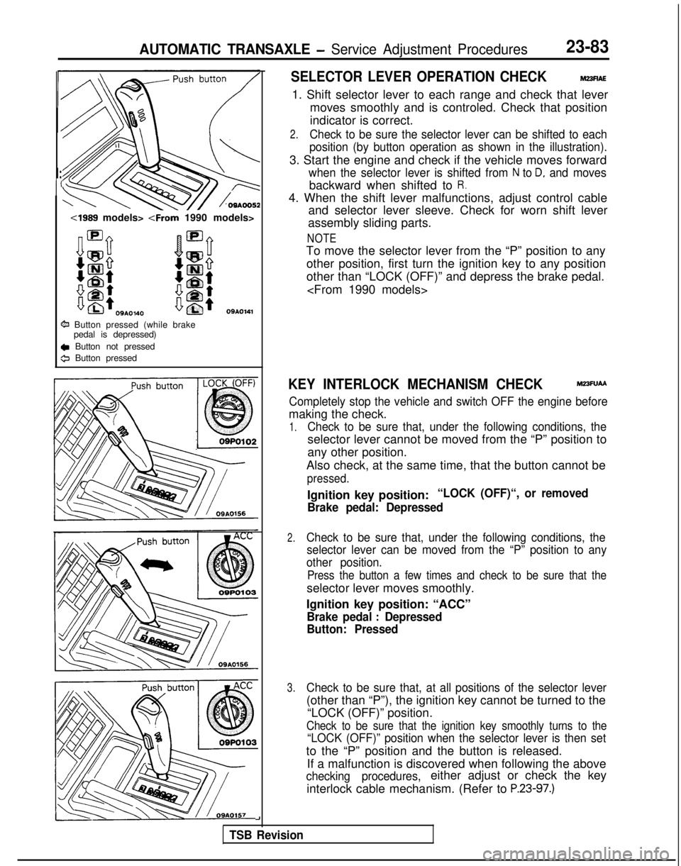
SELECTOR LEVER OPERATION CHECKM23flAE
1. Shift selector lever to each range and check that lever
moves smoothly and is controled. Check that position
indicator is correct.
2.Check to be sure the selector lever can be shifted to each
position (by button operation as shown in the illustration).
3. Start the engine and check if the vehicle moves forward
when the selector lever is shifted from N to D, and moves
backward when shifted to R.
4. When the shift lever malfunctions, adjust control cable and selector lever sleeve. Check for worn shift lever
assembly sliding parts.
NOTE
To move the selector lever from the “P” position to any
other position, first turn the ignition key to any position
other than “LOCK (OFF)” and depress the brake pedal.
KEY INTERLOCK MECHANISM CHECKM23FUAA
Completely stop the vehicle and switch OFF the engine before
making the check.
1.Check to be sure that, under the following conditions, the
selector lever cannot be moved from the “P” position to
any other position.
Also check, at the same time, that the button cannot be
pressed.
Ignition key position:“LOCK (OFF)“, or removed
Brake pedal: Depressed
2.Check to be sure that, under the following conditions, the selector lever can be moved from the “P” position to any
other position.
Press the button a few times and check to be sure that the
selector lever moves smoothly.
Ignition key position: “ACC”
Brake pedal : Depressed
Button: Pressed
3.Check to be sure that, at all positions of the selector lever
(other than “P”), the ignition key cannot be turned to the
“LOCK (OFF)” position.
Check to be sure that the ignition key smoothly turns to the
“LOCK (OFF)” position when the selector lever is then set
to the “P” position and the button is released.
If a malfunction is discovered when following the above
checking procedures,either adjust or check the key
interlock cable mechanism. (Refer to
P.23-97.)
-I
TSB Revision
Page 816 of 1273
25-2PROPELLER SHAFT - Specifications
SPEClFlCATjONS
The AWD vehicles have been discontinued from 1993 models.
GENERAL SPECIFICATIONSM2scA-
Specifications
Items M/T
Arr
Propeller shaft
Type
4 joint propeller shaft
4 joint propeller shaft
Length x
O.D.mm (in.)
Front 707 x 50.8 (27.8
x 2.00)707 x 50.8 (27.8 x
2.00)
Center 777.5 x 65 (30.8 x 2.56)
764.4 x
65 (30.1 x
2.56)
Rear530.5 x 50.8 (20.9 x
2.00)543.3 x 50.8 (21.4 x
2.00)
Universal joint Type
No. 1 (front) Cross typeCross typeNo.2
(center front)
Cross type Cross typeNo.3
(center rear) [Lobro joint
Equal velocity type Equal velocity type
No. 4 (rear) or
D.O.J.1Cross type
Cross type
Cross type universal joint bearing Needle roller bearing (oilless
type) Needle roller bearing (oilless
type)
Cross type universal joint
Journal O.D. mm (in.) 14.689 l.5783)
14.689 i.5783)
Equal velocity joint type Lobro joint
(oilless type)D.O.J. (oilless
type)
Equal velocity joint size O.D.mm
(in.) 94
(3.7)94 (3.7)
NOTEPropeller shaft length indicates the length between the center points of\
each joint.
SERVICE SPECIFICATIONSMz5c&-
Items Specifications
Standard value Journal axial play mm (in.)
0.02-0.06 (.0008-.0024)
Limit
Propeller shaft runout(Dial
indicator reading)
Frontmm (in.) 0.6 t.024) or less
Center mm (in.)
0.6
t.024) or less
Rearmm (in.)
0.6 (.024) or less
TORQUE SPECIFICATIONSMzxc-
Items1 Nm
Center bearing self locking nut
30-4022-29
Flange yoke to differential companion flange
30-3522-25
Center propeller shaft to center yoke
160-220116-159
Rear propeller shaft to companion flange
160-220116-159
Companion flange to Lobro joint assembly
30-4022-29
Companion flange to D.O.J. assembly
30-4022-2
9
ft.lbs.
TSB Revision
Page 819 of 1273
PROPELLER SHAFT - Propeller Shaft25-5
,.\
@Jjiig\ .!’
Lower
UpperSpacer
1060012 2.
3.
4.
Do not lower rear end of the vehicle as the oil will flow
out of the transfer.
Be cautious to avoid damage to the oil seal lip of the
transfer.
Use the special tool provided as a cover to prevent the
entry of foreign objects into the transfer.
INSPECTIONM2SGCAH
l Check the sleeve yoke, center yoke and flange yoke for wear, damage or cracks.
l Check the propeller shaft yokes for wear, damage or
cracks.
lCheck the propeller shaft for bends, twisting or damage.
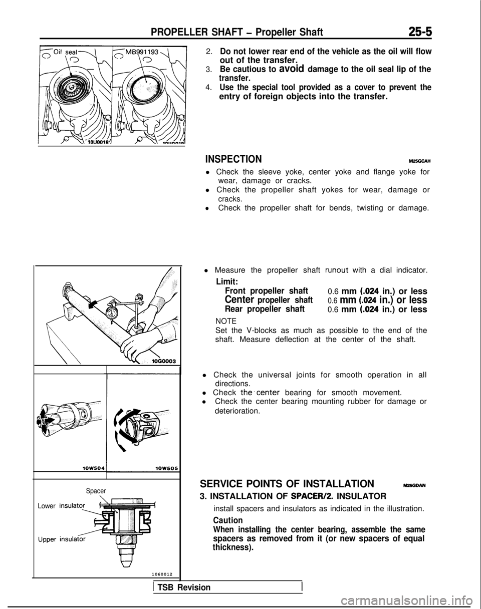
l Measure the propeller shaft runout
with a dial indicator.
Limit:
Front propeller shaft
0.6 mm (.024 in.) or less
Center propeller shaft0.6 mm (.024 in.) or less
Rear propeller shaft0.6 mm (.024 in.) or less
NOTE
Set the V-blocks as much as possible to the end of the
shaft. Measure deflection at the center of the shaft.
l Check the universal joints for smooth operation in all directions.
l Check
the’center bearing for smooth movement.
l Check the center bearing mounting rubber for damage or
deterioration.
SERVICE POINTS OF INSTALLATIONM25GDAN
3. INSTALLATION OF SPACER/P. INSULATOR
install spacers and insulators as indicated in the illustration.
Caution
When installing the center bearing, assemble the same
spacers as removed from it (or new spacers of equal
thickness).
1 TSB Revision
Page 835 of 1273
FRONT AXLE - Troubleshooting/Service Adjustment Procedures26-5
TROUBLESHOOTINGm6E6AA
Symptom
Vehicle pulls to one side Probable cause
Seizure of drive shaft ball joint
Abnormal wear, play or seizure of wheel bear-
ing
Remedy
Replace
Replace
Vibration
Shimmy Excessive noise Malfunction of front suspension or steering
Bend, damage or abnormal wear of drive shaft
Play in drive shaft and hub serration
Abnormal wear, play or seizure of wheel bear-
ing
Improper wheel alignment
Malfunction of front suspension or steering
Broken boot, grease leakage
Bend, damage or abnormal wear of drive shaft
Play of drive shaft and hub serration
Abnormal wear, play or seizure of center bearing Adjust or replace
Replace
Replace
Replace
Adjust or replace
Adjust or replace
Replace, repack grease
Replace
Replace
Replace
Abnormal wear, play or seizure of wheel bear-ing
Loose wheel nut
Malfunction of front suspension and steering
Replace
Retighten
Adjust or replace
SERVICE ADJUSTMENT
PROCEDURES
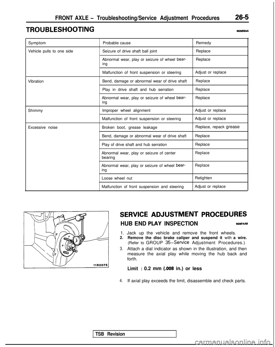
HUB END PLAY INSPECTIONM26FAAB
1. Jack up the vehicle and remove the front wheels.
2. Remove the disc brake caliper and suspend it with a wire.
(Refer to GROUP
35-Service Adjustment Procedures.)
3.Attach a dial indicator as shown in the illustration, and then measure the axial play while moving the hub back and
forth.
Limit: 0.2 mm (.008 in.) or less
4.If axial play exceeds the limit, disassemble and check parts.
TSB Revision