1989 MITSUBISHI GALANT cruise control
[x] Cancel search: cruise controlPage 113 of 1273
ENGINE
ENGINE ASSEMBLY
IEMOVAL AND INSTALLATION
Pre-removal Operationl Eliminating fuel pressure in fuel lines
(Refer to GROUP 13-On-Vehicle lnspectior
of MFI Components.)*Removal of the hood
(Refer to GROUP 42-Hood.)
eDraining of engine coolant(Refer to GROUP 00-Maintenance
Service.:@Removal of transaxle assembly
(Refer to GROUP 22, 23-Transaxle.)*Removal of radiator assembly
(Refer to GROUP 14-Radiator.)
MIISA-6
Post-installation Operationl installation of radiator assembly(Refer to GROUP 14-Radiator.)l Installation of transaxle assembly
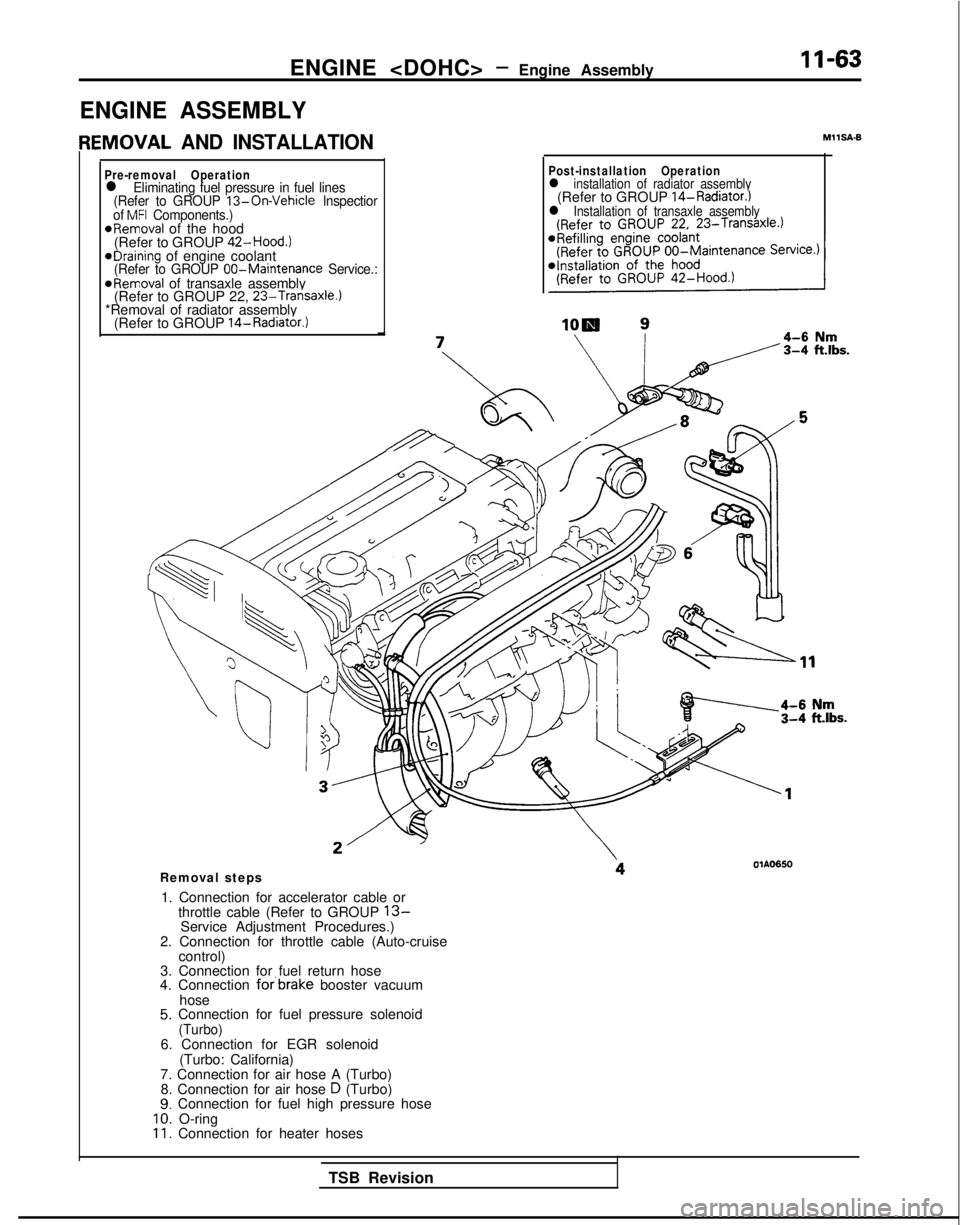
Removal steps
1. Connection for accelerator cable or throttle cable (Refer to GROUP
13-Service Adjustment Procedures.)
2. Connection for throttle cable (Auto-cruise control)
3. Connection for fuel return hose
4. Connection
forbrake booster vacuum
hose
5. Connection for fuel pressure solenoid(Turbo)6. Connection for EGR solenoid (Turbo: California)
7. Connection for air hose A (Turbo) 8. Connection for air hose
D (Turbo)9. Connection for fuel high pressure hose10. O-ring11. Connection for heater hoses
TSB Revision
Page 143 of 1273
13-1
FUEL
CONTENTSM’ISAA--
AUTO-CRUISE CONTROL SYSTEM.............
.
332
AUTO-CRUISE CONTROL ............................. 408
SERVICE ADJUSTMENT PROCEDURES .................397
Accelerator Cables
inspectron and Adjustment ........
.
398 Auto-cruise
Control System Inspection
..............397
Individual Parts Inspection ......................
401SPECfAL
TOOLS
.....................................
333
SPECIFICATIONS .................................... 332
TROUBLESHOOTING ................................. 334
Auto-cruise Control Components Location ..........368
Auto-cruise Control
Related Harnesses
..........365
Check Chart
Check Chart
Circuit Diagram ................................
371input Checking................................
.
366
On-board Diagnostic Checking ......................
361Troubleshooting Quick-reference Chart
.
334
Troubleshooting Quick-reference Chart
ENGINE CONTROL...............................
.
328
ENGINE CONTROL ..................................
330
SERVICE ADJUSTMENT PROCEDURES .................329
Accelerator Cable inspectron and Adjustment
...........329
Accelerator Switch Inspection and Adjustment ..........329
SPECIFICATIONS ....................................
328
TROUBLESHOOTlNG................................
.
328
Accelerator
Cable and Accelerator Pedal .............
.
328
FUEL SYSTEM
FUEL FILTER .........................................
327
FUEL LINE AND VAPOR LINE
.
326
FUEL LINE AND VAPOR LINE
.
324
FUEL TANK
.
322
FUELTANK
.
318
GENERAL INFORMATION ............................ 196
ON-VEHICLE INSPECTION OF MFI
COMPONENTS
......251
Air Conditioning Switch and A/C Compressor Clutch Relay .....................................
285
Barometric Pressure Sensor .................... 266
Boost Meter
311Camshaft Position Sensor ........................
.
277Closed Throttle Position Switch
.....................
.
274
Component Location .............................
251Components Inspection Pocedure
................. 255
Crankshaft Position Sensor ..................... 280EGR
Solenord
...................
.
307EGR Temperature Sensor
.............
.
288Engrne Control Module Power Ground
................
.
257
Engine Coolant Temperature Sensor ..................
268Evaporative Emission Purge Solenoid .................
.
307
Fuel Pressure Solenoid
307Fuel Pressure Test...............................
.
312
Fuel Pump ...................................... 258
Heated Oxygen Sensor ............................ 290
Idle Air Control Motor (Stepper Motor) ................
238Ignition Coil and Ignition Power Transistor .............
.
302
Ignition Switch-ST .................................. 284
Ignition Switch-ST and Park/Neutral Position Switch .....284
Injectors .......................................
295Inspection of Engine Control Module Terminal
Voltage .......................................
.
315
Intake Air Temperature Sensor .......................263
Knock Sensor
Power Steering Pressure Switch ......................
284Power Supply and Ignition Switch ...................
.
255Resistor
..............................
.
298Terminal Voltage Check Chart
......................
.
315Throttle Position Sensor
..........................
.
270Turbocharger Waste Gate Solenoid
.........
.
309 Vehicle
Speed Sensor
............................... 284
Volume Air Flow Sensor ............................
261SERVICE ADJUSTMENT PROCEDURES ...............
.
245
Basic
idle Speed Adjustment .......................
.
245
Closed Throttle Position Switch (Fixed
SAS)Adjustment ......................................
.
250
Curb
Idle Speed Inspection
..........................245Throttle Body (Throttle Valve Area) Cleaning
...........
.
248Throttle Position Sensor Adjustment
..................
.
248
SPECIALTOOLS...................................
.
204
SPECIFICATIONS ...................................
201TROUBLESHOOTING ...............................
.
205
Check Engine/Malfunction Indicator Lamp ..............205
Circuit Diagram .................................... 214
Clear Memory of Diagnostic Trouble Code .............
211Explanation and Precaution Related to Harness
Checking ......................................
.
205Explanation of Troubleshooting Procedures
............
.
205Failsafe/Back-up Functions List
.....................
.
211Fuel tank and Fuel Line
............................
.
244
Read Out Diagnostic Trouble Code ...................
211Troubleshooting Table
.............................
.
208(CONTINUED ON NEXT PAGE)
Page 203 of 1273
FUEL SYSTEM
CLOSED THROTTLE POSITION SWITCH
control -Idle speed control
motor connector
@ Component sideconnector
@ Harness sideconnector
II
ISC plunger
_---__
III*Throttle shaft turning angle
01209
2
-
Engine control module
1
6
3
OFF
aI
ON
-z
Closed throttleDosition switch
lFUO479
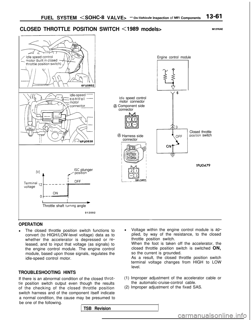
OPERATION
l
The closed throttle position switch functions to
convert (to HIGH/LOW-level voltage) data as to
whether the accelerator is depressed or
re-
leased, and to input that voltage (as signals) to
the engine control module. The engine control module, based upon those signals, regulates the
idle-speed control motor.
TROUBLESHOOTING HINTS
l Voltage within the engine control module is ap-
plied, by way of the resistance, to the closed
throttle position switch.
When the foot is taken off the accelerator, the
closed throttle position switch is switched ON,
so the current is grounded.
As a result, the closed throttle position switch
terminal voltage changes from HIGH to LOW
level.
If there is an abnormal condition of the closed throt-
tle position switch output even though the results
of the checking of the closed throttle position
switch harness and of the component itself indicate
a normal condition, the cause may be presumed tobe one of the following.
TSB Revision
(1) Improper adjustment of the accelerator cable or the automatic-cruise-control cable.
(2) Improper adjustment of the fixed SAS.
Page 416 of 1273
13-274FUEL SYSTEM
CLOSED THROTTLE POSITION SWITCH
Terminal
voltage
Throttle shaft
turning angle Engine control module
1
Throttle position
sensor connector
Component side
connector
Harness side
connector
6FU1355
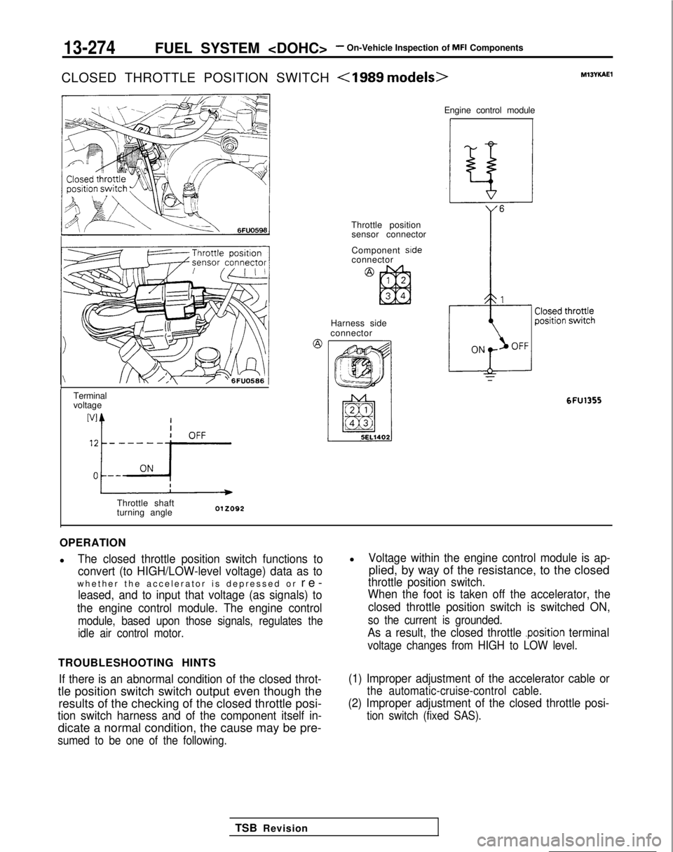
OPERATION
l
The closed throttle position switch functions to
convert (to HIGH/LOW-level voltage) data as to
whether the accelerator is depressed or re
-
leased, and to input that voltage (as signals) to
the engine control module. The engine control
module, based upon those signals, regulates the
idle air control motor.
TROUBLESHOOTING HINTS
If there is an abnormal condition of the closed throt-
tle position switch switch output even though the results of the checking of the closed throttle posi-
tion switch harness and of the component itself in-
dicate a normal condition, the cause may be pre-
sumed to be one of the following.
lVoltage within the engine control module is ap-
plied, by way of the resistance, to the closed
throttle position switch.
When the foot is taken off the accelerator, the
closed throttle position switch is switched ON,
so the current is grounded.
As a result, the closed throttle .position terminal
voltage changes from HIGH to LOW level.
(1) Improper adjustment of the accelerator cable or
the automatic-cruise-control cable.
(2) Improper adjustment of the closed throttle posi-
tion switch (fixed SAS).
TSB Revision
Page 471 of 1273
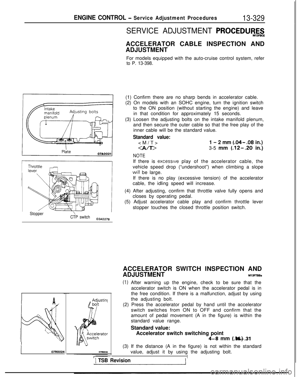
ENGINE CONTROL - Service Adjustment Procedures13-329
SERVICE ADJUSTMENT PROCEDW,E,t&
ACCELERATOR CABLE INSPECTION AND
ADJUSTMENT
For models equipped with the auto-cruise control system, refer
to P. 13-398.
(1) Confirm there are no sharp bends in accelerator cable.
(2) On models with an SOHC engine, turn the ignition switch to the ON position (without starting the engine) and leave
in that condition for approximately 15 seconds.
(3) Loosen the adjusting bolts on the intake manifold plenum, and then secure the outer cable so that the free play of theinner cable will be the standard value.
Standard value:
1 - 2 mm (.04- .08
in.)
-a/T>3-5 mm (.12-.20 in.)
NOTE
If there is excessrve play of the accelerator cable, the
vehicle speed drop (“undershoot”) when climbing a slope will
be large.
If there is no play (excessive tension) of the accelerator
cable, the idling speed will increase.
(4) After adjusting, confirm that throttle valve fully opens and closes by operating pedal.
(5) Adjust accelerator cable play and confirm throttle lever
stopper touches the closed throttle position switch.
Stopper\CTP switch03AO278
A
.-\\‘\.\ ‘\
!4
:l/.\\ \\‘\ I\*\\”
j 07R0024
ACCELERATOR SWITCH INSPECTION AND
ADJUSTMENTM13FTBBa
(1) After warning up the engine, check to be sure that theaccelerator switch is ON when the accelerator pedal is in
the free condition. If there is a malfunction, adjust by using
the adjusting bolt.
(2) Press the accelerator pedal by hand until the accelerator switch switches from ON to OFF and confirm that the
amount of pedal movement (A in the figure) is within the
standard value range.
Standard value: Accelerator switch switching point
4-8 mm (.16-.31 in.)
(3) If the distance (A in the figure) is not within the standard value, adjust it by using the adjusting bolt.
I1 TSB Revision
Page 474 of 1273
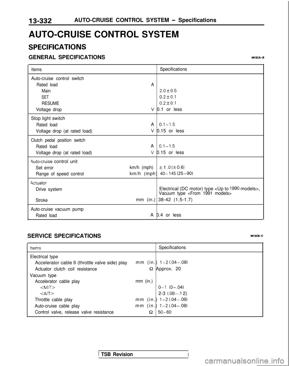
13-332
AUTO-CRUISE CONTROL SYSTEM - Specifications
AUTO-CRUISE CONTROL SYSTEM
SPECIFICATIONS
GENERAL SPECIFICATIONSM13CA--B
Items
Auto-cruise control switch
Rated load Main
SET
RESUME
Voltage drop
Stop light switch
Rated load
Voltage drop (at rated load)
Clutch pedal position switch
Rated load
Voltage drop (at rated load)
4uto-cruise control unit
Set errorRange of speed control
4ctuator
Drive system
Stroke
Auto-cruise vacuum pump
Rated load
Specifications
A
2.0f0.5
0.2fO.l 0.2t-0.1
V 0.1 or less
A
0.1-1.5
V 0.15 or less
A
0.1-1.5
V 0.15 or less
km/h (mph)IL 1 .O (kO.6)
km/h (mph) 40-145
(25-90)
Electrical (DC motor) type
mm (in.) 38-42 (1.5-1.7)
A 0.4 or less
SERVICE SPECIFICATIONS
Ml3CB-.C
ItemsSpecifications
Electrical type
Accelerator cable B (throttle valve side) play mm (in.) l-2 (.04-.08)
Actuator clutch coil resistanceQ Approx. 20
Vacuum type
Accelerator cable play mm (in.)
Gv-r~2-3 (.08-.I 2)
Throttle cable playmm (in.) l-2 (.04-.08)
Auto-cruise cable playmm (in.) l-2
(.04-.08)
Control valve, release valve resistance52 50-60
1 TSB RevisionI
Page 475 of 1273
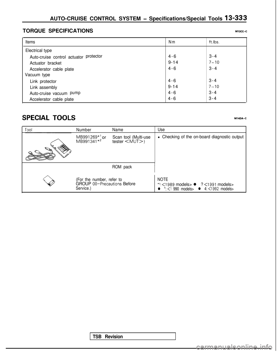
AUTO-CRUISE CONTROL SYSTEM - Specifications/Special Tools 13-333
TORQUE SPECIFICATIONSMlOCC-.C
ItemsNmftlbs.
Electrical type
Auto-cruise control actuator protector
4-
6
3-4
Actuator bracket9-147-10
Accelerator cable plate4-
6
3-4
Vacuum type
Link protector
4-
6
3-4
Link assembly9-147-10
Auto-cruise vacuumpump4-
6
3-4
Accelerator cable plate4-
6
3-4
SPECIAL TOOLSM14DA-C
Number Name Use
MB991 269*’
orMB991341 **Scan tool (Multi-usel Checking of the on-board diagnostic output
tester
ROM pack
(For the number, refer to
NOTEGROUP 00-Precautions BeforeService.)‘1: <1989 models> l ? <1991 models>l *: l 4: <1992
models>
TSB Revision
Page 476 of 1273
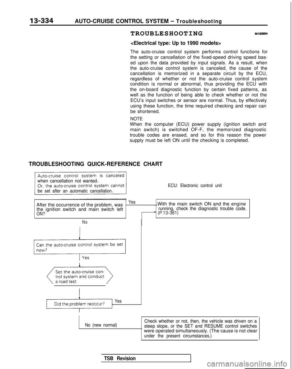
13-334AUTO-CRUISE CONTROL SYSTEM - Troubleshooting
TROUBLESHOOTIN
G
MlJEBDH
The auto-cruise control system performs control functions for
the setting or cancellation of the fixed-speed driving speed bas-
ed upon the data provided by input signals. As a result, when
the auto-cruise control system is canceled, the cause of the
cancellation is memorized in a separate circuit by the ECU,
regardless of whether or not the auto-cruise control system
condition is normal or abnormal, thus providing the ECU with
the on-board diagnostic function by certain fixed patterns, as
well as the function of being able to check whether or not the
ECU’s input switches or sensor are normal. Thus, by effectively
using these function, the time required checking and repair can
be shortened.
NOTE
When the computer (ECU) power supply (ignition switch andmain switch) is switched OF-F, the memorized diagnostic
trouble codes are erased, and so for this reason the power
supply must be left ON until the checking is completed.
TROUBLESHOOTING QUICK-REFERENCE CHART
when cancellation not wanted.
be set after an automatic cancellation. ECU: Electronic control unit
After the occurrence of the problem, wasYes. With the main switch ON and the engine
the ignition switch and main switch leftrunning, check the diagnostic trouble code.
ON?+ (P.13-361)
No
Can the auto-cruise control system be set
_r-l;
Yes
No (new normal)Check whether or not, then, the vehicle was driven on a
steep slope, or the SET and RESUME control switches
were operated simultaneously. (The cause is not clear
under the present circumstances.)
TSB RevisionI