Page 24 of 1273
00-22GENERAL - Special Handling Instructions for AWD Models
REAR WHEEL MEASUREMENTS
After placing the rear wheels on the brake tester, follow thesame procedures as for the front wheel measurements.
WHEEL BALANCE
FRONT WHEEL MEASUREMENTS
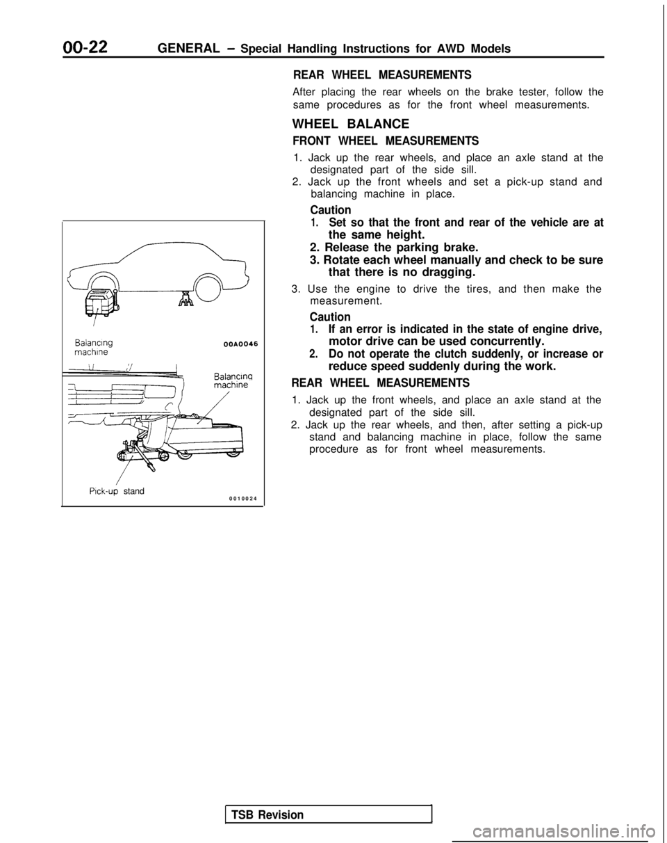
1. Jack up the rear wheels, and place an axle stand at the designated part of the side sill.
2. Jack up the front wheels and set a pick-up stand and balancing machine in place.
Caution
1.Set so that the front and rear of the vehicle are at
the same height. Balancing
machlne
OOA0046
Balancw
Pick-up stand
0010024
TSB Revision
2. Release the parking brake.
3. Rotate each wheel manually and check to be sure
that there is no dragging.
3. Use the engine to drive the tires, and then make the measurement.
Caution
1.If an error is indicated in the state of engine drive,
motor drive can be used concurrently.
2.Do not operate the clutch suddenly, or increase or
reduce speed suddenly during the work.
REAR WHEEL MEASUREMENTS
1. Jack up the front wheels, and place an axle stand at the
designated part of the side sill.
2. Jack up the rear wheels, and then, after setting a pick-up stand and balancing machine in place, follow the same
procedure as for front wheel measurements.
Page 25 of 1273
GENERAL - General Data and Specifications00-23
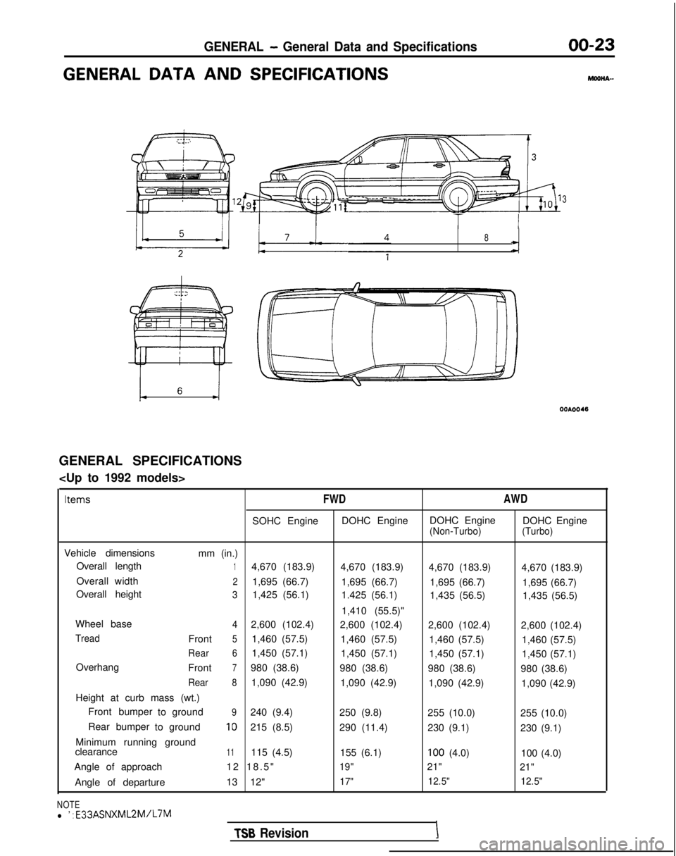
GENERAL DATA AND SPECIFICATIONSMOOHA-
3
I TT I
8
GENERAL SPECIFICATIONS
Items
FWD
AWD
SOHC EngineDOHC EngineDOHC Engine
DOHC Engine(Non-Turbo) (Turbo)
Vehicle dimensions
mm (in.)
Overall length
14,670 (183.9) 4,670 (183.9)4,670 (183.9) 4,670 (183.9)
Overall width
21,695 (66.7) 1,695 (66.7)1,695 (66.7) 1,695 (66.7)
Overall height
31,425 (56.1) 1.425 (56.1)1,435 (56.5) 1,435 (56.5)
1,410 (55.5)"
Wheel base
42,600 (102.4) 2,600 (102.4)2,600 (102.4) 2,600 (102.4)
TreadFront51,460 (57.5)1,460 (57.5)1,460 (57.5) 1,460 (57.5)
Rear61,450 (57.1)1,450 (57.1)1,450 (57.1) 1,450 (57.1)
Overhang Front
7980 (38.6)980 (38.6)980 (38.6) 980 (38.6)
Rear81,090 (42.9)1,090 (42.9)1,090 (42.9) 1,090 (42.9)
Height at curb mass (wt.) Front bumper toground
9240 (9.4)
250 (9.8)255 (10.0) 255 (10.0)
Rear bumper toground
10215 (8.5)
290 (11.4)230 (9.1) 230 (9.1)
Minimum running ground
clearance
11115 (4.5) 155 (6.1)100 (4.0)100 (4.0)
Angle of approach 12 18.5
"
19"21"21"
Angle of departure
13 12"17"12.5"
12.5"
NOTEl ’ : E33ASNXML2M/L7M
TSB RevisionI
Page 27 of 1273
GENERAL - General Data and Specifications00-25
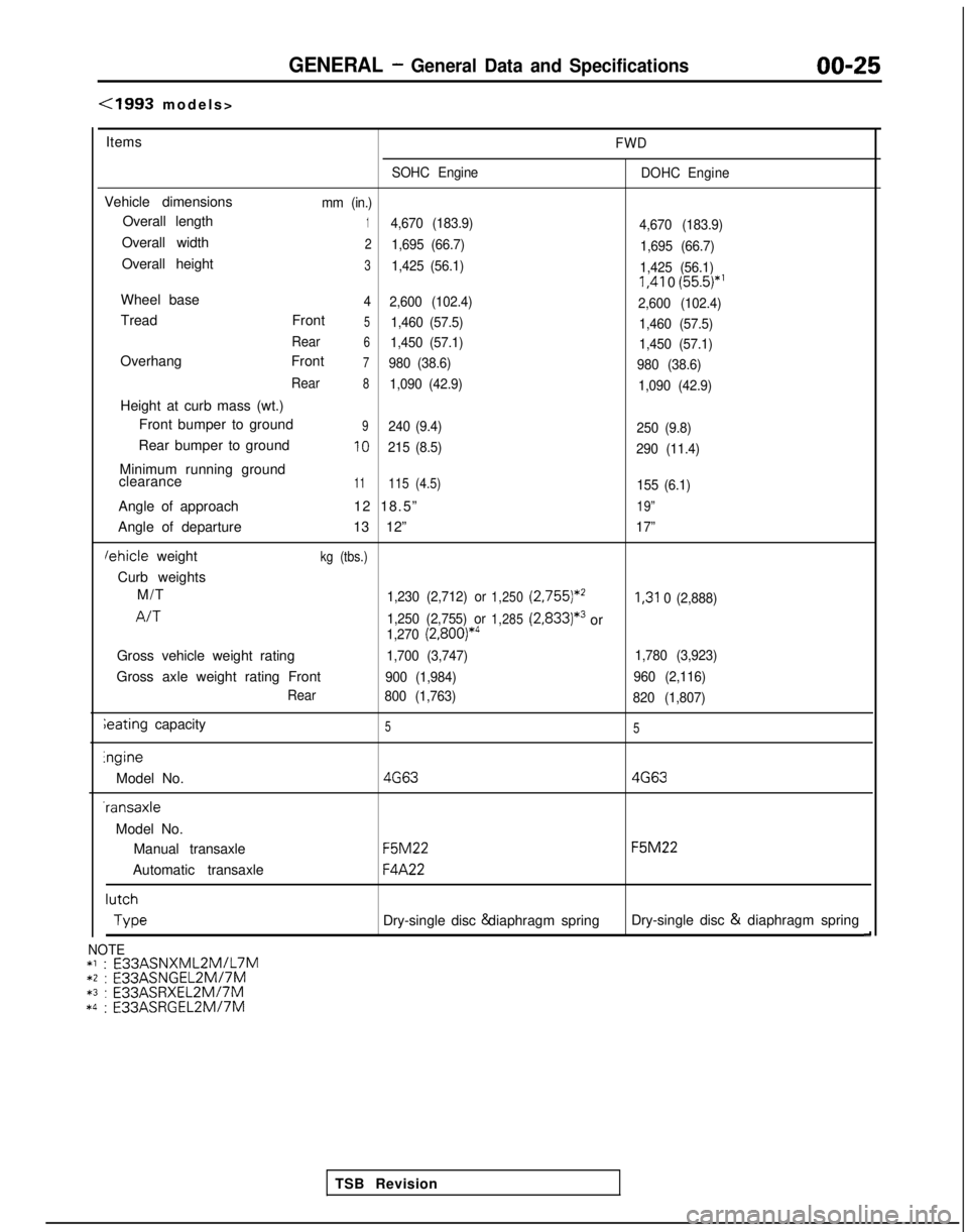
(1993 models
>
Items
FWD
SOHC Engine DOHC Engine
Vehicle dimensionsmm (in.)
Overall length14,670 (183.9)
4,670 (183.9)
Overall width21,695 (66.7)1,695 (66.7)
Overall height31,425 (56.1)1,425 (56.1) I,41
0
(55.5)*’
Wheel base4
2,600 (102.4)
2,600 (102.4)
Tread Front51,460 (57.5)1,460 (57.5)
Rear
61,450 (57.1) 1,450 (57.1)
Overhang Front7980 (38.6)980 (38.6)
Rear
81,090 (42.9) 1,090 (42.9)
Height at curb mass (wt.)
Front bumper to ground
9240 (9.4) 250 (9.8)
Rear bumper to ground10215 (8.5)290 (11.4)
Minimum running ground
clearance11115 (4.5)155 (6.1)
Angle of approach 12 18.5”19”
Angle of departure13 12”17”
lehicle weightkg (tbs.)
Curb weights
M/T
1,230 (2,712) or1,250 (2,755)*’I,31
0 (2,888)
A/T1,250 (2,755) or1,285(2,833)*3or1,270 (2,800)*4
Gross vehicle weight rating1,700 (3,747) 1,780 (3,923)
Gross axle weight rating Front900 (1,984)960 (2,116)
Rear 800 (1,763)
820 (1,807)
ieating capacity55lngine
Model No.
4G634G63 -ransaxle
Model No. Manual transaxle
F5M22 F5M22
Automatic transaxle
F4A22 lutch
Type
Dry-single disc & diaphragm spring
Dry-single disc &
diaphragm spring
d
TSB Revision
NOTE*l : E33ASNXML2MlL7M*2 : E33ASNGEL2MI7M*3 :
E33ASRXEL2M/7M*4 :
E33ASRGEL2M/7M
Page 253 of 1273
FUEL SYSTEM - Fuel Tank13-111
03R0297
Vapor hose
mmin.)Fillerhose
i2.l
B
3FOO7
A
1
Flare nut
Skure side
03Yo43
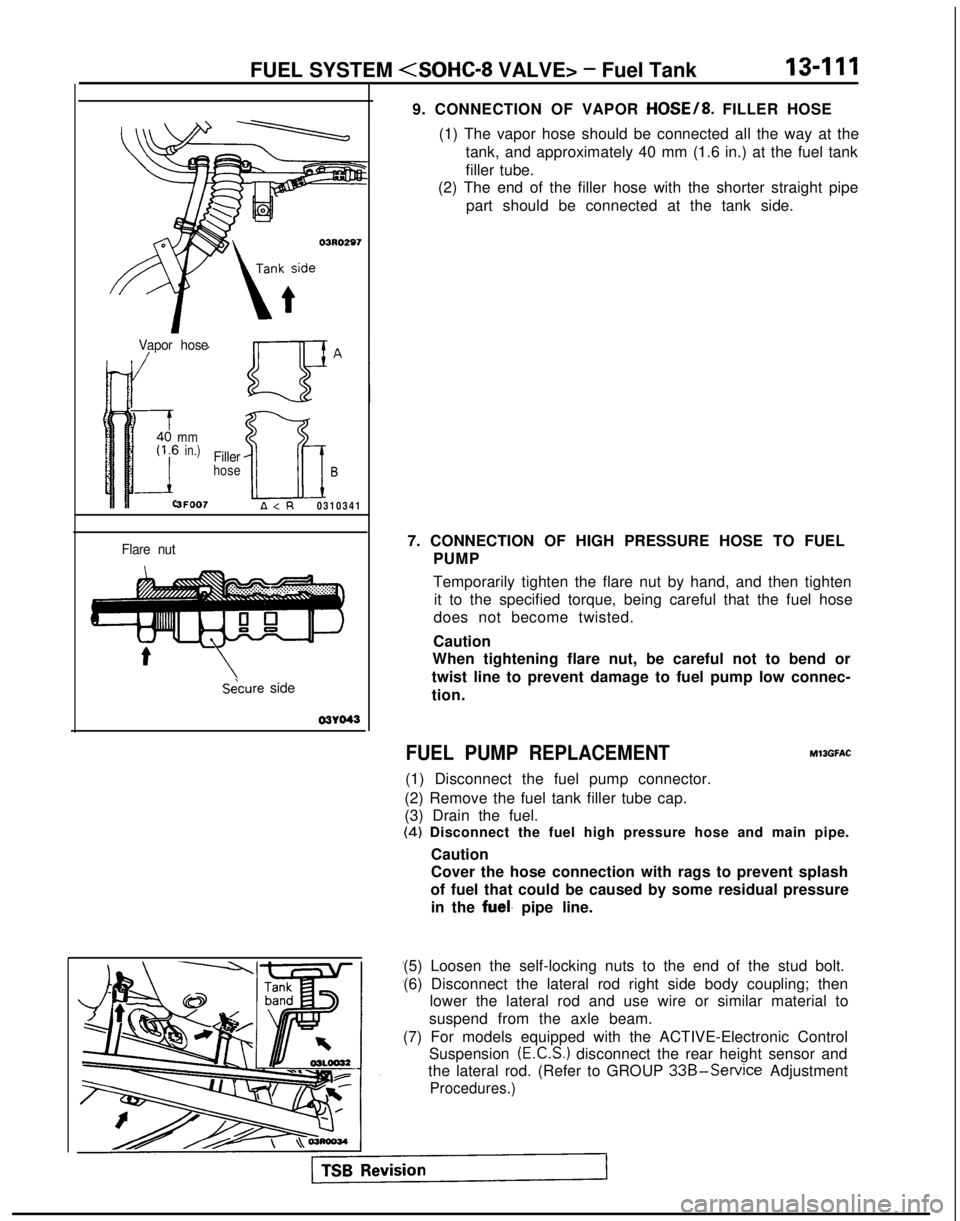
9. CONNECTION OF VAPOR HOSE/8. FILLER HOSE
(1) The vapor hose should be connected all the way at the tank, and approximately 40 mm (1.6 in.) at the fuel tank
filler tube.
(2) The end of the filler hose with the shorter straight pipe
part should be connected at the tank side.
7. CONNECTION OF HIGH PRESSURE HOSE TO FUEL PUMP
Temporarily tighten the flare nut by hand, and then tightenit to the specified torque, being careful that the fuel hose
does not become twisted.
Caution
When tightening flare nut, be careful not to bend or
twist line to prevent damage to fuel pump low connec-
tion.
FUEL PUMP REPLACEMENT
(1) Disconnect the fuel pump connector.
(2) Remove the fuel tank filler tube cap.
(3) Drain the fuel. MllGFAC
(4)
Disconnect the fuel high pressure hose and main pipe.
Caution
Cover the hose connection with rags to prevent splash
of fuel that could be caused by some residual pressure in the
fuel. pipe line.
(5) Loosen the self-locking nuts to the end of the stud bolt.
(6) Disconnect the lateral rod right side body coupling; then lower the lateral rod and use wire or similar material to
suspend from the axle beam.
(7) For models equipped with the ACTIVE-Electronic Control Suspension
(E.C.S.) disconnect the rear height sensor and
the lateral rod. (Refer to GROUP
33B-Service Adjustment
Procedures.)
Page 254 of 1273
13-112FUEL SYSTEM
VALVE> - Fuel Tank
03L0018
QcD ua .
CFa
cc
0c aa0u0aa
Positioning projection
03L0009
(8) Remove
the fuel pump installation screws and the bolt for
holding the fuel pump (at the lower side of the fuel tank),
and then remove the fuel pump from the fuel tank.
(9) Align the three positioning projections of the packing with the holes in the fuel pump.
(lO)When the fuel pump is installed, the holding bolt at the lower side of the fuel tank should be installed first.
Care should be taken at this time that the O-ring is not
pinched.
(1 l)For models equipped with the ACTIVE-E.C.S., check the operation of the ACTIVE-E.C.S. after installation of the rearheight sensor. (Refer to GROUP
33B-Service AdjustmentPrnrwiI irps II I ““VW-. W.S.,
1 TSB Revision
Page 462 of 1273
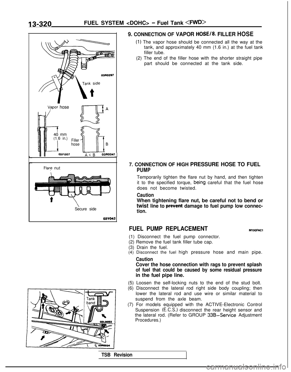
13-320FUEL SYSTEM - Fuel Tank
03RO297
V/apor hose
mmin.)
3FOO7
Filler
hoseB
A
Flare nut
\Secure side 03YO43
Ll
9. CONNECTION OF VAPOR HOSE/8. FILLER HOSE
(1) The vapor hose should be connected all the way at the
tank, and approximately 40 mm (1.6 in.) at the fuel tank
filler tube.
(2) The end of the filler hose with the shorter straight pipe part should be connected at the tank side.
7. CONNECTION OF HIGH PRESSURE HOSE TO FUEL
PUMP
Temporarily tighten the flare nut by hand, and then tighten
it to the specified torque,
bein,g careful that the fuel hose
does not become twisted.
Caution
When tightening flare nut, be careful not to bend or
twist line to prevent damage to fuel pump low connec-
tion.
FUEL PUMP REPLACEMENT
(1) Disconnect the fuel pump connector.
(2) Remove the fuel tank filler tube cap.
(3) Drain the fuel.
Ml3GFAt.X
(4) Disconnect the fuel high pressure hose and main pipe.
Caution
Cover the hose connection with rags to prevent splash
of fuel that could be caused by some residual pressure
in the fuel pipe line.
(5) Loosen the self-locking nuts to the end of the stud bolt.
(6) Disconnect the lateral rod right side body coupling; then
lower the lateral rod and use wire or similar material to
suspend from the axle beam.
(7) For models equipped with the ACTIVE-Electronic Control Suspension
(E.C.S.) disconnect the rear height sensor and
the lateral rod. (Refer to GROUP
33B-Service Adjustment
Procedures.)
TSB Revision
Page 463 of 1273
FUEL SYSTEM - Fuel Tank 13-321
I03LOO18
-
QGB ua \
a=
C-CT
0a
c oc3i20’0Qaa
Positidning projection
03L0000
(8) Remove the fuel pump installation screws and the bolt for
holding the fuel pump (at the lower side of the fuel tank),
and then remove the fuel pump from the fuel tank.
(9) Align the three positioning projections of the packing with the holes in the fuel pump.
(lO)When the fuel pump is installed, the holding bolt at the
lower side of the fuel tank should be installed first. Care should be taken at this time that the O-ring is not
pinched.
(1 l)For models equipped with the ACTIVE-E.C.S., check the operation of the ACTIVE-E.C.S. after installation of the rear
height sensor. (Refer to GROUP
33B-Service Adjustment
Procedures.)
Page 566 of 1273
14-14COOLING - Thermostat
04UOO18
< 1993 models> 04AOlZIStandard value:
Valve opening temperature DOHC, SOHC
8VALVE
SOHC 1 GVALVE
Full-open temperatureDOHC, SOHC
8VALVE
SOHC 16VALVE
NOTE
88°C (19O’F)
82°C (180°F)
100°C (212°F)
95°C (203°F)
Measure valve height when fully closed. Calculate lift by
measuring the height when fully open.
SERVICE POINTS OF INSTALLATIONMWGEAG
6. INSTALLATION OF THERMOSTAT
Install the thermostat so that the flange fits perfectly to therecessed seat of the thermostat case or intake manifold.
2. CONNECTION OF RADIATOR LOWER HOSE/ 1. RADIATOR UPPER HOSE
Align the mating marks on the radiator hose and hose clamp and then connect them; then seat the clamp to the
trace marks of the previous connection.
Caution If the radiator hose and hose clamp mating marks are
not aligned and installed, water leaks may occur.
TSB Revision