1989 MITSUBISHI GALANT height
[x] Cancel search: heightPage 956 of 1273
![MITSUBISHI GALANT 1989 Service Repair Manual ACTIVE-ELECTRONIC CONTROL SUSPENSION - Troubleshooting 33B-17
CHECKING ACCORDING TO CHARTS CLASSIFIED BY THE MALFUNCTION SYMPTOM
[A] DIAGNOSTIC TROUBLE CODE NO.54
No
Yes
b Excessive vehicle-height ad- MITSUBISHI GALANT 1989 Service Repair Manual ACTIVE-ELECTRONIC CONTROL SUSPENSION - Troubleshooting 33B-17
CHECKING ACCORDING TO CHARTS CLASSIFIED BY THE MALFUNCTION SYMPTOM
[A] DIAGNOSTIC TROUBLE CODE NO.54
No
Yes
b Excessive vehicle-height ad-](/manual-img/19/57312/w960_57312-955.png)
ACTIVE-ELECTRONIC CONTROL SUSPENSION - Troubleshooting 33B-17
CHECKING ACCORDING TO CHARTS CLASSIFIED BY THE MALFUNCTION SYMPTOM
[A] DIAGNOSTIC TROUBLE CODE NO.54
No
Yes
b Excessive vehicle-height ad-justment
(overload) overload). time (due to -Unload the vehicle and turn* the ignition key to OFF; then
restart the engine and check
whether or not the system
functions normally.
Is the installation position of Nothe height sensor correct?
Yes Improper setting of the heightc sensor, or malfunction of the
height sensor. l Correct the installationcposition of the height sen-
sor, or adjust the vehicle
-height sensor rod.
l Check the height sensor. Refer to troubleshooting
hints [IO] and
[ll]classified by circuit.
Are the front strut and rear
NoMalfunction of the rolling
shock absorber unit air spr-* diaphragm.
Repair the rolling diaphragm,
or replace the shock absorber
ings in normal condition?Lunit.
(become folded)
Yes
Is the sound of operation
NoThe solenoid valves remain
heard from each solenoid closed, or there is air leakage
valve necessary for th
e
’ due to a malfunction of the
vehicle-height adjustment? valve seat.
Yes
Is the air pressure in the
vehicle-height adjustment
Nopressure line 950 kPa (135
psi) or higher?
I
Yes Damaged or disconnected
wiring of the high-pressure
switch, or incorrect vehicle
-height adjustment pressureline.
l Check the high-pressure switch circuit.
* Refer to troubleshooting hint [5] classified by circuit.
l Correct the clogging pro-
blem, or replace the air
tube.
Control unit malfunction.
[B] DIAGNOSTIC TROUBLE CODE NO.55
- No
Does the compressor func-
tion normally?
Yes Replace the control unit.c l Power is not supplied to
the compressor.Refer to troubleshooting
hint
[18] classified by cir-
cuit.
0 Improper compressor com- pression.
Is the air pressure in the
Novehicle-height adjustment
pressure line 760 kPa (108psi) or lower? High-pressure
switch
isRefer to troubleshooting hint
shorted____* [5] classified by circuit.
Yes Air leakage.
TSB RevisionI
Page 957 of 1273
33B-18 ACTIVE-ELECTRONIC CONTROL SUSPENSION - Troubleshooting
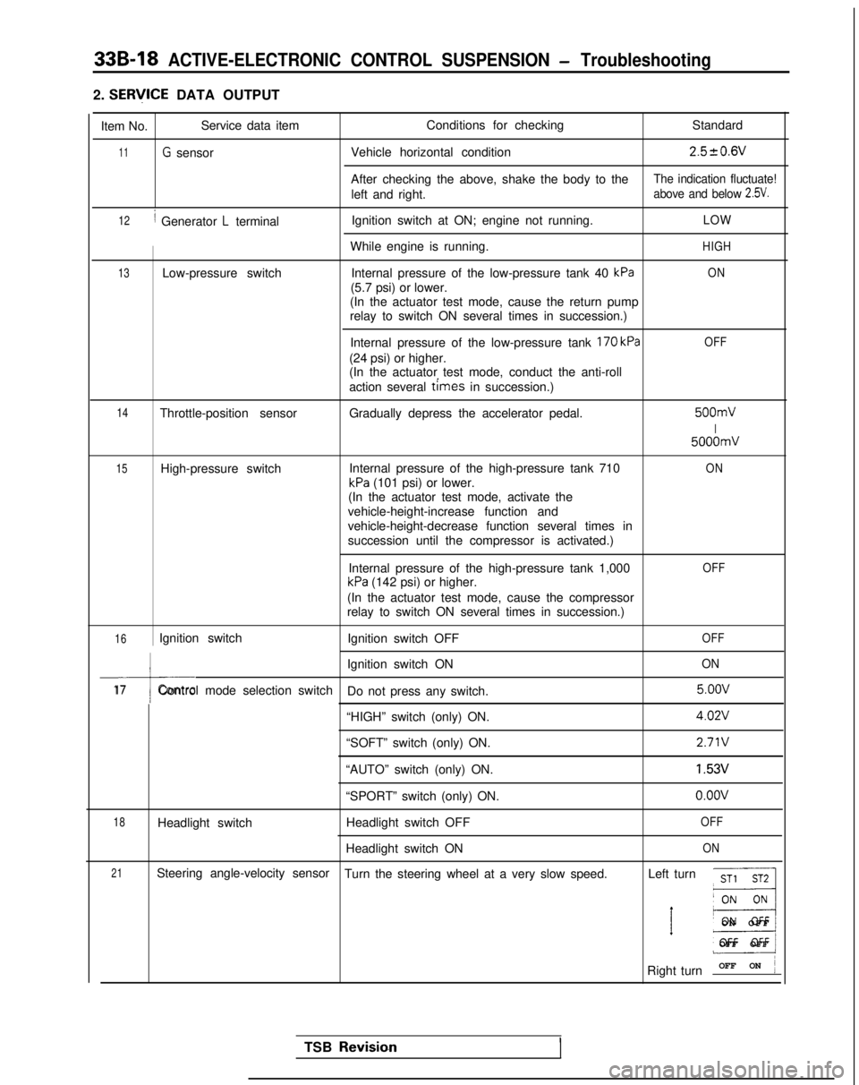
2. SERlflCE DATA OUTPUT
Item No. Service data item
Conditions for checking
Standard
11G sensorVehicle horizontal condition2.520.6V
After checking the above, shake the body to theThe indication fluctuate!
left and right.above and below 2.5V.
12/ Generator L terminalIgnition switch at ON; engine not running.LOW
While engine is running.HIGH
13Low-pressure switch
Internal pressure of the low-pressure tank 40 kPaON
(5.7 psi) or lower.
(In the actuator test mode, cause the return pump
relay to switch ON several times in succession.)
Internal pressure of the low-pressure tank
170 kPa
(24 psi) or higher.
(In the actuator test mode, conduct the anti-roll
action several
times in succession.)
OFF
14Throttle-position sensor Gradually depress the accelerator pedal. 500mV
I
5000mV
15High-pressure switch
Internal pressure of the high-pressure tank 710ON
kPa (101 psi) or lower.
(In the actuator test mode, activate the
vehicle-height-increase function and
vehicle-height-decrease function several times in
succession until the compressor is activated.)
Internal pressure of the high-pressure tank 1,000
kPa (142 psi) or higher.
OFF
(In the actuator test mode, cause the compressor
relay to switch ON several times in succession.)
16Ignition switch Ignition switch OFFOFF
I
Ignition switch ONON
17Control mode selection switch
Do not press any switch. 5.oov
“HIGH” switch (only) ON.
4.02V
“SOFT” switch (only) ON.2.71V
“AUTO” switch (only) ON.1.53V
“SPORT” switch (only) ON.o.oov
18Headlight switch Headlight switch OFFOFF
Headlight switch ONON
21Steering angle-velocity sensor
Turn the steering wheel at a very slow speed. Left turnST1 ST2
__I
’ E3
ON OF
F
OFF OFF
Right turn OFF ON
j
TSB Revisio.nI
Page 958 of 1273
ACTIVE-ELECTRONIC CONTROL SUSPENSION - Troubleshootina 33B-19
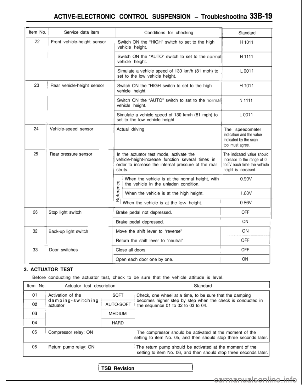
rItem No. IService data itemConditions for checking
Switch ON the “HIGH” switch to set to the high
vehicle height.Standard
H 1011
Switch ON the “AUTO” switch to set to the norma
vehicle height.N 1111
Simulate a vehicle speed of 130 km/h (81 mph) to
set to the low vehicle height.ILO011
-cSwitch ON the “HIGH switch to set to the high
vehicle height.HI011
Switch ON the “AUTO” switch to set to the norma
vehicle height.
N 1111
Simulate a vehicle speed of 130 km/h (81 mph) to
set to the low vehicle height.LOO11
Actual driving The speedometer
indication and the value
indicated by the scan
tool must agree.
In the actuator test mode, activate theThe indicated value should
vehicle-height-increase function several times inIncrease to the range of 0
order to increase the internal pressure of the rearto 5V each time the vehicle
struts.height is increased.-
8
i When the vehicle is at the normal height, with
iE Ithe vehicle in the unladen condition. 0.9ov
Front vehicle-height sensor
23
’/Rear vehicle-height sensor
-4
c
24Vehicle-speed sensor
t25Rear pressure sensor
Fa,%When the vehicle is at the high height.
[r i When the vehicle is at the low height.
1.6OV
I0.86VT
26Stop light switch Brake pedal not depressed.IOFFI
Brake pedal depressed.IONIc
32Back-up light switch
33
TDoor switches
I
Move the shift lever to “reverse”
-E-----l
-
Return the shift lever to “neutral”
Close all doors.
IOFF/
Open each door one by one.ION
3. ACTUATOR TEST Before conducting the actuator test, check to be sure that the vehicle a\
ttitude is level.
Item No. Actuator test description Standard
01~
!l
Activation of theSOFT
damping-switching i
I Check, one wheel at a time, to be sure that the damping
02 actuator
t’ becomes higher step by step when the check is conducted in
AUTO-SOFT ~the sequence 01 to 02 to 03 to 04.
03MEDIUM
04 HARD
05
Compressor relay: ON The compressor should be activated at the moment of the
setting to item No. 05, and then should stop three seconds later.
Return pump relay: ON ~
The return pump should be activated at the moment of the
setting to item No. 06, and then should stop three seconds later.
06
1 TSB Revision
Page 960 of 1273
ACTIVE-ELECTRONIC CONTROL SUSPENSION - Troubleshooting 33B-21
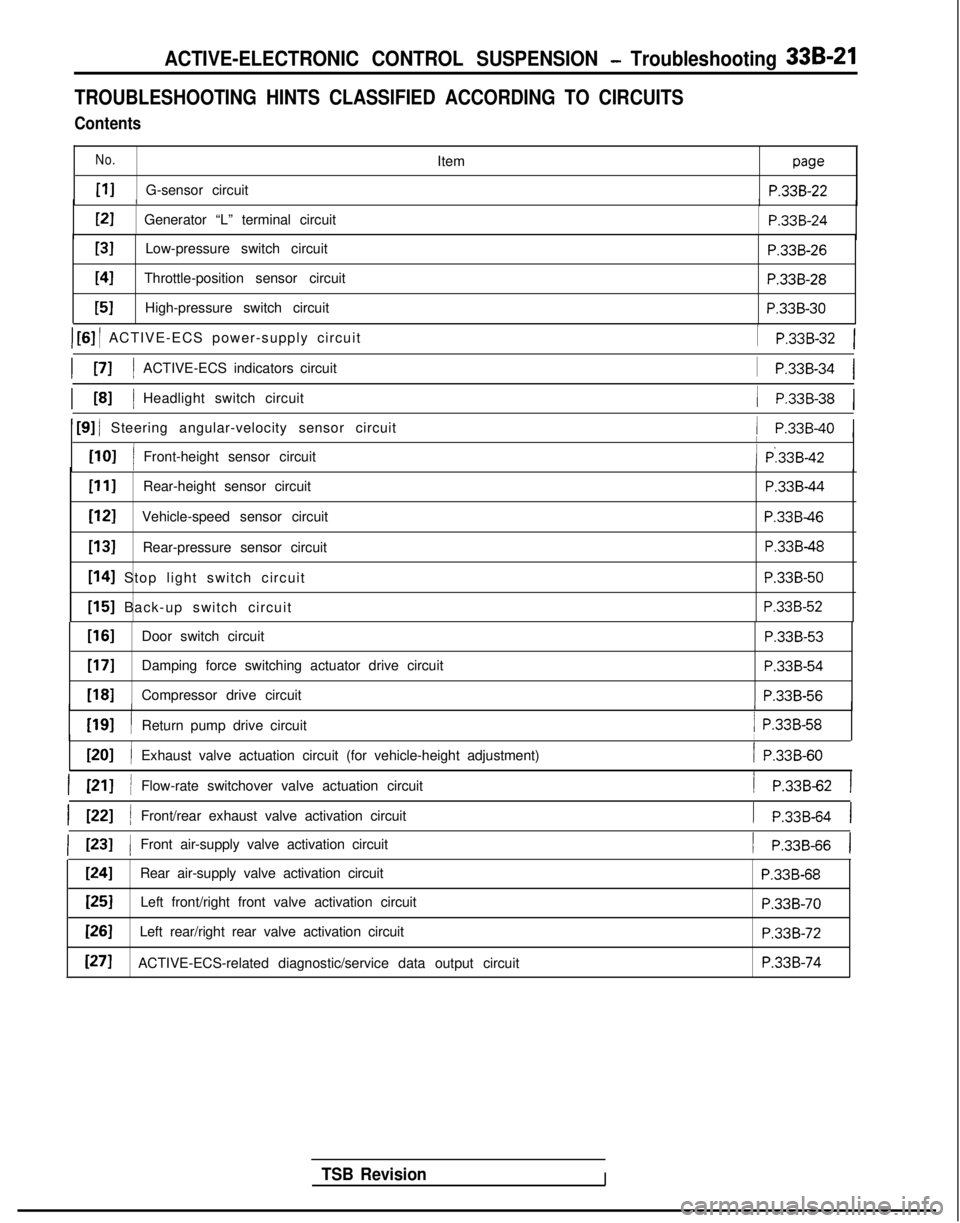
TROUBLESHOOTING HINTS CLASSIFIED ACCORDING TO CIRCUITS
Contents
No.
PIG-sensor circuitItem
paw
P.33B-22/IPI
Generator “L” terminal circuit
P.33B-24
[31Low-pressure switch circuitP.33B-26
I41Throttle-position sensor circuitP.33B-28
[51High-pressure switch circuit P.338-30
) [6] / ACTIVE-ECS power-supply circuit
I PI IACTIVE-ECS indicators circuit
1 P.33B-32 1
1
P.33B-34 1
/ P.33B-38 1I L81 IHeadlight switch circuit
1 [9] / Steering angular-velocity sensor circuit/ P.33B-40 1
[lOI /
I
Front-height sensor circuit( P:33B-42I
PIIRear-height sensor circuit
[I21Vehicle-speed sensor circuit
[13]Rear-pressure sensor circuit
[I41 Stop light switch circuit
[I51 Back-up switch circuit
P.33B-44
P.33B46
P.33B-48 P.338-50
P.33B-52
TSB RevisionI
[If31Door switch circuitP.33B-53
[17]Damping force switching actuator drive circuit
P.338-54
1181Compressor drive circuitP.33B-561
WI
I
I
Return pump drive circuit/ P.33B-58
ml /
I
Exhaust valve actuation circuit (for vehicle-height adjustment)/ P.33B-60
I PII /Flow-rate switchover valve actuation circuit/ P.33B-62 1
I WI /Front/rear exhaust valve activation circuit1 P.33B-64 I
( 1231 1Front air-supply valve activation circuit1 P.33B-66 1
1241Rear air-supply valve activation circuitP.33B-68
[25]Left front/right front valve activation circuitP.33B-70
[=ILeft rear/right rear valve activation circuitP.33B-72
[271ACTIVE-ECS-related diagnostic/service data output circuitP.33B-74
Page 962 of 1273

ACTIVE-ELECTRONIC CONTROL SUSPENSION - Troubleshooting 33B-23
Operation
The G-sensor detects the amount of acceleration
that is generated (to the left or right) when the
vehi-
response to acceleration, and these changes are
cle body turns. Applying the principle of the dif-
taken out as changes of voltage. Within the coil,
ferential transformer, the magnetic field changes silicon oil is enclosed in order to suppress the vibra-
tion of the movable iron core. Note that the
G-sen-
when the movable iron core within the coil moves in
Diagnostic sor is a special sensor for control of rolling.
When signals that are otherwise virtually
in-
conceivable are input due to damaged or discon-
a heavy-line circuit, the alarm light illuminates and
control is as described in the table below.
netted wiring or a short-circuit or similar problem of
Diagnostic No.Attitude controlDamplng force
controlVehicle-heightcontrol Switch acceptanceHIGH
SPORT AUTO SOFT
I11Rolling control
only stops Normal operation
Normal operation Accept
Service data indication
Code NoIndication
Standard value Display
11G-sensor output voltage 2.5V
when vehicle is horizontal 11: G SNSR:
2.5V
ECU terminal voltages (when connector is connected)
Terminal
NoCondition
Terminal
voltageIII
34 Power supply for sensor When the ECU is activated7.3vI
28G-sensor output signal
35 Sensor circuit earth When stoppedi
When wiring is damaged or disconnected
Constantly 2.5V
ov
ov
TSB Revision
-.
Checking the G-sensor circuit (with the connector disconnected)
Terminal ConnectIon
destination or MeasurementNomeasured part Tester connection
Check conditionStandard
28 G-sensor output
Resistance
28-2ConstantlyContinuity
34G-sensor power source
Resistance34-1ConstantlyContinuity
Troubleshooting hints
Malfunction
mode Malfunction probable causeMatfunctIonNoteSilicon
oil leakage
Because the sillcon
oil for
suppresslon of
l Rolling control occurs frequently-
vlbratlons of the G-sensor movable iron core is leaktng due to a collision.
the sensitivity is
oversensitive.
Damaged or
disconnected
earth line The ground line is damaged or disconnected.
l-Malfunction is not detected because the There are times of a feeling of
ground line is grounded to the G sensor’s body incompatibility of the rolling control
l
itself, however, noise is easily picked up. Rolling
control occurs suddenly; an error
occurs
Page 964 of 1273
ACTIVE-ELECTRONIC CONTROL SUSPENSION - Troubleshooting 33B-25
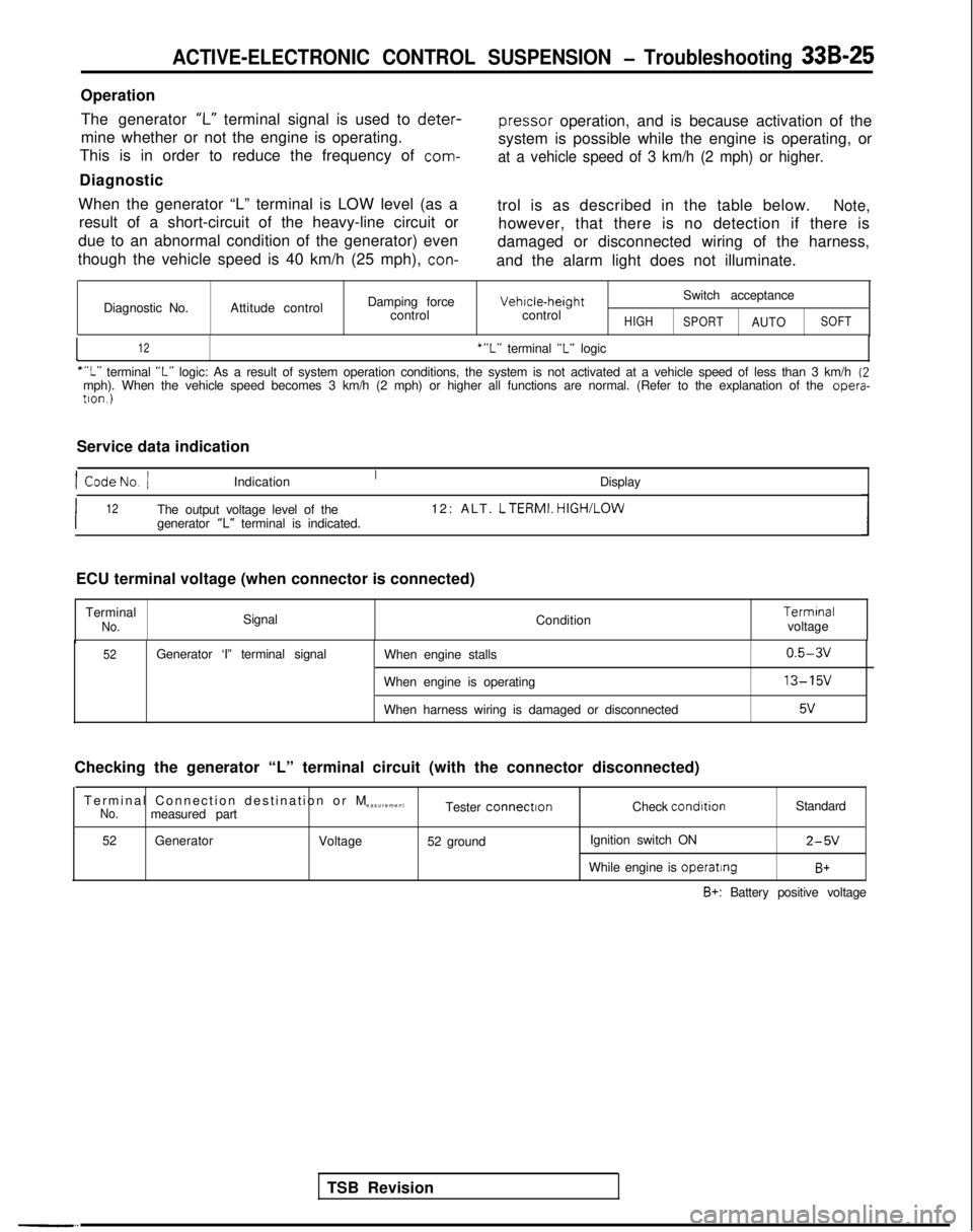
OperationThe generator
‘I-” terminal signal is used to deter-
pressor
operation, and is because activation of the
mine whether or not the engine is operating.
This is in order to reduce the frequency of
com-
system is possible while the engine is operating, or
at a vehicle speed of 3 km/h (2 mph) or higher.
Diagnostic
When the generator “L” terminal is LOW level (as a result of a short-circuit of the heavy-line circuit or
due to an abnormal condition of the generator) even
though the vehicle speed is 40 km/h (25 mph),
con-
trol is as described in the table below.Note,
however, that there is no detection if there is
damaged or disconnected wiring of the harness,
and the alarm light does not illuminate.
Diagnostic No. Attitude control Damping force
control Vehrcle-height
control
HIGH
Switch acceptance
SPORTAUTOSOFT
I12‘“L” terminal “L” logic
““L” terminal “L” logic: As a result of system operation conditions, the system is not ac\
tivated at a vehicle speed of less than 3 km/h (2mph). When the vehicle speed becomes 3 km/h (2 mph) or higher all fun\
ctions are normal. (Refer to the explanation of the opera-
tron.)
Service data indication
1 CodeNo. /Indication Display
I12The output voltage level of the12: ALT. LTERMI.
HIGH/LOW
generator “L” terminal is indicated.
TSB Revision
ECU terminal voltage (when connector is connected)
Terminal
No.Signal Condition Termrnal
voltage
52Generator ‘I” terminal signal When engine stalls
When engine is operating
When harness wiring is damaged or disconnected0.5-3v
13-15v
5v
Checking the generator “L” terminal circuit (with the connector d\
isconnected)
Terminal Connection destination or
M
easurement
No.measured part Tester connectronCheck condrtion
Standard
52 Generator
Voltage52 ground Ignition switch ON
2-5V
While engine is operatingB+
B+: Battery positive voltage
Page 966 of 1273
ACTIVE-ELECTRONIC CONTROL SUSPENSION - Troubleshooting 33B-27
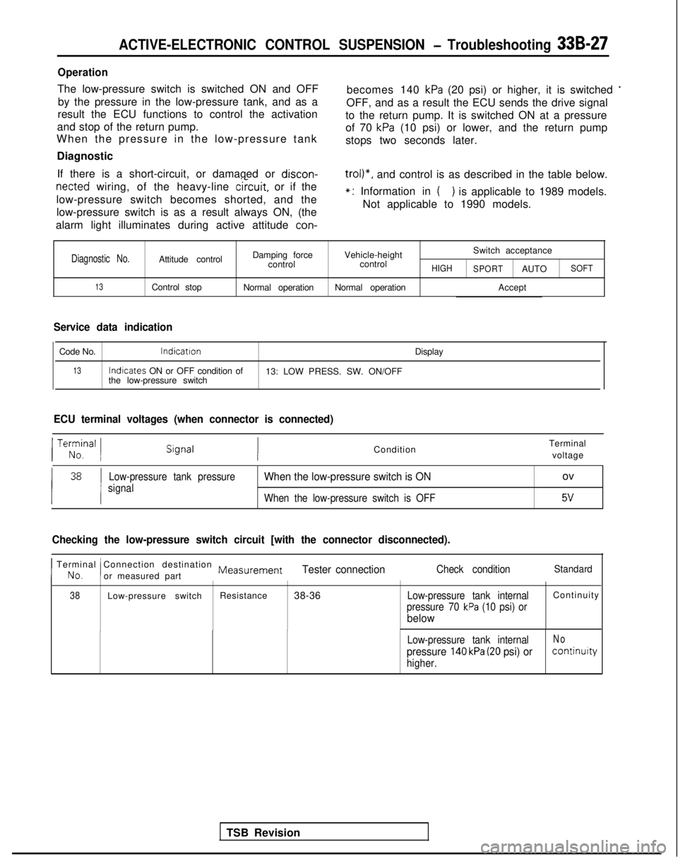
Operation
The low-pressure switch is switched ON and OFFby the pressure in the low-pressure tank, and as a becomes 140 kPa (20 psi) or higher, it is switched *
result the ECU functions to control the activation
OFF, and as a result the ECU sends the drive signal
and stop of the return pump. to the return pump. It is switched ON at a pressure
When the pressure in the low-pressure tank of 70
kPa (10 psi) or lower, and the return pump
stops two seconds later.
Diagnostic
If there is a short-circuit, or damaged or discon-
netted wiring, of the heavy-line
circuit,
or if the
low-pressure switch becomes shorted, and the low-pressure switch is as a result always ON, (the
trol)“, and control is as described in the table below.
alarm light illuminates during active attitude
con-
*: Information in () is applicable to 1989 models.
Not applicable to 1990 models.
Diagnostic No.Attitude control Damping force
Vehicle-height Switch acceptance
control controlHIGH
SPORTAUTOSOFT
13Control stop Normal operationNormal operation Accept
Service data indication
Code No.lndicatron
Display
13Indicates
ON or OFF condition of
13: LOW PRESS. SW. ON/OFF
the low-pressure switch
ECU terminal voltages (when connector is connected)
TSB Revision
/ Te;;,nal 1Condition Terminal
voltage
Low-pressure tank pressure
signalWhen the low-pressure switch is ONov
When the low-pressure switch is OFF5v
Checking the low-pressure switch circuit [with the connector disconnecte\
d).
I No.
Terminal Connection destination Measurement
!or measured partTester connectionCheck conditionStandard
38Low-pressure switch Resistance
38-36Low-pressure tank internalContinuit
y
pressure 70 kPa (10 psi) or
below
Low-pressure tank internalNo
pressure 140 kPa (20 psi) orcontinuity
higher.
Page 972 of 1273
ACTIVE-ELECTRONIC CONTROL SUSPENSION - Troubleshooting 33B-33
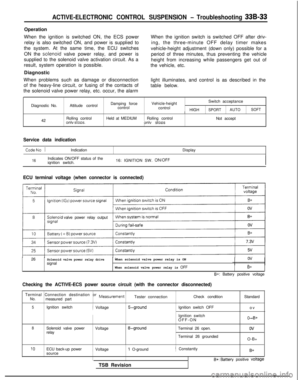
Operation
When the ignition is switched ON, the ECS power relay is also switched ON, and power is supplied to
the system. At the same time, the ECU switches
ON the solenoid
valve power relay, and power is
supplied to the solenoid valve activation circuit. As a
result, system operation is possible.
Diagnostic
When problems such as damage or disconnection of the heavy-line circuit, or fusing of the contacts of
the solenoid valve power relay, etc. occur, the alarm When the ignition switch is switched OFF after driv-
ing, the three-minute OFF delay timer makes
vehicle-height adjustment (down only) possible for a period of three minutes, thus preventing the vehicle
height from increasing while passengers get out of
the vehicle, etc.
light illuminates, and control is as described in the
table below.
Diagnostic No. 42 Attitude control
Rolling control
onlv stoos.
Damping force
Vehicle-height Switch acceptance
control control
/ HIGHSPORTAUTOSOFT
Held at MEDIUM
Rolling control
Not acceptonlv stoos
Service data indication
CodeNo /Indication Display
16Indicates ON/OFF status of the
iqnition switch. 16: IGNITION SW. ON/OFF
ECU terminal voltage (when connector is connected)
valve power relay output
26
Solenoid valve power relay drivesignalWhen solenoid valve power relay is ON
When solenoid valve power relay is OFFB+
B+: Battery positive voltage
Checking the ACTIVE-ECS power source circuit (with the connector discon\
nected)
Terminal Connection destination or Measurement ’No.measured part Tester connection
Check condition
5Ignition switchi Voltage5-groundIgnition switch OFF
Ignition switch
OFF-O
N
8Solenoid valve power
Voltage8-groundTerminal 26 open.
relay
Terminal 26 groundedStandard
o
v
O+B+
ov
O-B+
10ECU back-up power
sourcei Voltage1 O-ground
TSB Revision/ ConstantlyB+
B+: Batten/ positive voltage