1989 MITSUBISHI GALANT steering wheel adjustment
[x] Cancel search: steering wheel adjustmentPage 58 of 1273
II-8ENGINE
8 VALVE
W Tlmlng belt side
il6
16
727
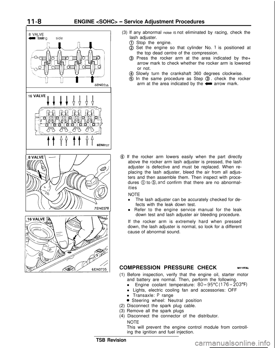
(3) If any abnormal noise IS not eliminated by racing, check the
lash adjuster.
@ Stop the engine.
@ Set the engine so that cylinder No. 1 is positioned at
the top dead centre of the compression.
@ Press the rocker arm at the area indicated by the+ arrow mark to check whether the rocker arm is lowered
or not.
@ Slowly turn the crankshaft 360 degrees clockwise.
@ In the same procedure as Step 0, check the rocker
arm at the area indicated by the
0 arrow mark.
@ If the rocker arm lowers easily when the part directly
above the rocker arm lash adjuster is pressed, the lash
adjuster is defective and must be replaced. When re-
placing the lash adjuster, bleed the air from all adjus-
ters and then assemble them. Then inspect with proce-
dures
@ to 0, and confirm that there are no abnormal-
ities
NOTE
lThe lash adjuster can be accurately checked for de-
fects with the leak down test.
l Refer to the engine service manual for the leak down test and lash adjuster air bleeding procedure.
If the rocker arm is extremely hard when pressed
down, the lash adjuster is normal, so look for a different
cause of abnormal sound.
COMPRESSION PRESSURE CHECK
MllFFAL
(1) Before inspection, verify that the engine oil, starter motor and battery are normal. Then, perform the following.
l Engine coolant temperature:
80- 95°C
(176- 203°F)
l Lights, electric cooling fan and accessories: OFF
l Transaxle:
P range
0 Steering wheel: Neutral position
(2) Disconnect the spark plug cable.
(3) Remove all the spark plugs
(4) Disconnect the connector of the distributor.
NOTE
This will prevent the engine control module from controll- ing the ignition and fuel injection.
TSB Revision
Page 59 of 1273

ENGINE
(5) Cover the spark plug holes with a cloth, etc., and crank the engine. Then verify that no foreign material sticks to the
cloth, etc.
Caution
1. During cranking, be especially careful of the spark plug
installing hole.
2.Very hot water, oil, fuel, etc., which may have entered
the cylinder somehow, will violently spout through the spark plug hole if the compression is measured in the
entrapped state. This is very dangerous.
MANIFOILD VACUUM INSPECTIONMllFNAC
(6)
(7)
(8)
Set up the compression gauge in the spark plug mounting
hole.
Fully open the throttle valve, and cranking the engine,
measure the compression pressure.
Standard value:
<8VALVE>1,250 kPa (178 psi) [250-400 rpm]
< 1 Ei VALVE>
1,300 kPa (185 psi) [250-400 rpm]
Limit:
(8 VALVE>880 kPa (125 psi) [250-400 rpm]
[250-400 rpm]
Measure the compression pressure of each cylinder, and
verify that the pressure difference among the cylinders is
less than the limit value.
Limit: max. 100
kPa (14 psi)
(9) If a cylinder’s compression pressure or pressure difference IS outside
the limit, fill a small amount of engine oil through
the spark plug hole and repeat Items (7) and (8) above.
@ If the compression is increased when the oil is filled, the piston and/or cylinder wall may be worn or
damaged.
@ If the compression is not increased even though the oil is filled, the valve may be thermally seized, the valve
contact may be improper or pressure may leak at the
gasket.
(10) Connect the connector of the distributor.
(11) Install the spark plug and spark plug cable.
(12)Erase the diagnostic trouble code with the Scan tool or re-
connect the battery (-)
cable
10 seconds or more after it
was disconnected.
NOTE
This will erase the memory of the diagnostic trouble code
which
resu,lted from disconnection of the distributor con-
nector.
(1) Before inspection and adjustment, put the vehicle into the
followin~g state.
l Engine coolant temperature:
85-95°C (185-203°F)
l
Ligt-Its, electric, cooling fan, and accessories: OFF
l Transaxle: Neutral
(N or P for vehicles with an automa-
tic transaxle)
l Steering wheel: Neutral position
(2) Check that the idling revolution speed is normal.
TSB Revision
Page 60 of 1273
II-IOENGINE
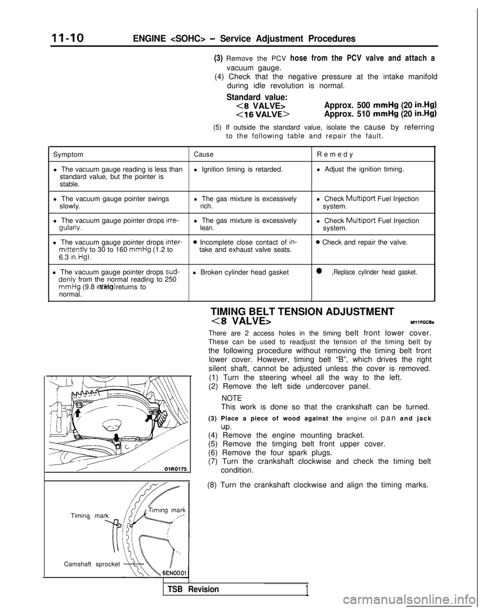
(3) Remove the PCV hose from the PCV valve and attach a
vacuum gauge.
(4) Check that the negative pressure at the intake manifold
during idle revolution is normal.
Standard value:
(8 VALVE>Approx. 500 mmHg (20 in.Hg)
<16VALVE>Approx. 510 mmHg (20 in.Hg)
(5) If outside the standard value, isolate the cause by referring
to the following table and repair the fault.
Symptom
CauseRemed
y
l The vacuum gauge reading is less than l Ignition timing is retarded.l Adjust the ignition timing.
standard value, but the pointer is
stable.
l The vacuum gauge pointer swings l The gas mixture is excessivelyl Check
Multiport Fuel Injection
slowly.rich.system.
l The vacuum gauge pointer drops irre-
l The gas mixture is excessively
l Check
Multiport Fuel Injectiongularly.lean.system.
l The vacuum gauge pointer drops inter-
0 Incomplete close contact of in-0 Check and repair the valve.mittently to 30 to 160
mmHg
(1.2 to take and exhaust valve seats.
6.3 in.Hg).
l The vacuum gauge pointer drops sud-l Broken cylinder head gasketl ,Replace cylinder head gasket. denly
from the normal reading to 250 mmHg
(9.8 in.Hg). then returns to
normal.
/ OlR0175
condition.
Timina mark
‘timing mark._*-
Camshaft sprocket TIMING BELT TENSION ADJUSTMENT
(8 VALVE>MllFGCEa
There are 2 access holes in the timing belt front lower cover.
These can be used to readjust the tension of the timing belt by
the following procedure without removing the timing belt front lower cover. However, timing belt “B”, which drives the right
silent shaft, cannot be adjusted unless the cover is removed. (1) Turn the steering wheel all the way to the left.
(2) Remove the left side undercover panel.
NOTE
This work is done so that the crankshaft can be turned.
(3) Place a piece of wood against the engine oil pan and jac
k
up.(4) Remove the engine mounting bracket.
(5) Remove the timging belt front upper cover.
(6) Remove the four spark plugs.
(7) Turn the crankshaft clockwise and check the timing belt
(8) Turn the crankshaft clockwise and align the timing marks.
TSB Revision1
Page 108 of 1273
11-58ENGINE
4 Timing belt sideI
6EN0515
(3) lf
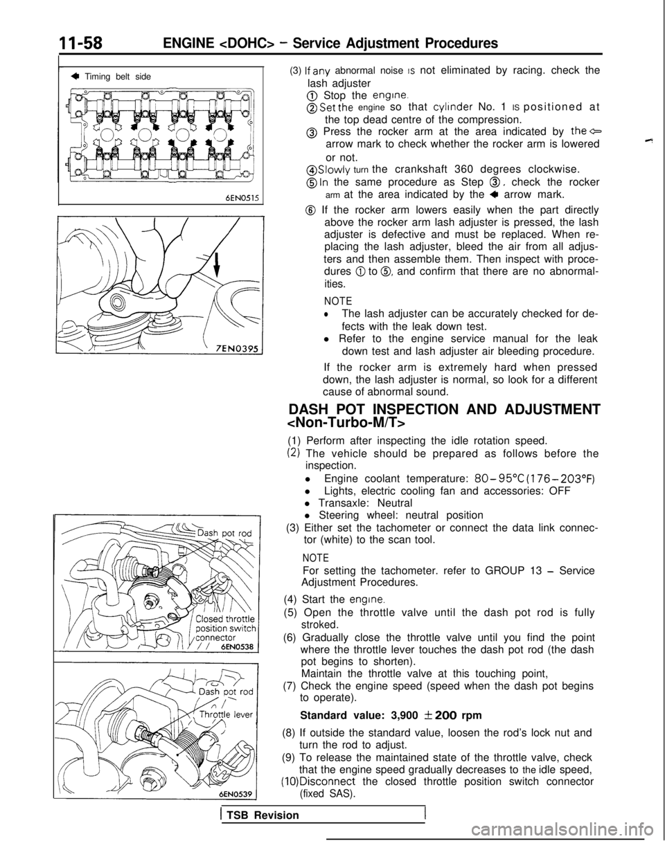
any abnormal noise IS not eliminated by racing. check the
lash adjuster
@ Stop the engine.
@ Set the engine so that cylinder
No. 1 IS positioned at
the top dead centre of the compression.
@ Press the rocker arm at the area indicated by the+
arrow mark to check whether the rocker arm is lowered
or not.
@ Slowly turn the crankshaft 360 degrees clockwise.
@ ln the same procedure as Step 0, check the rocker
arm at the area indicated by the
4 arrow mark.
@ If the rocker arm lowers easily when the part directly above the rocker arm lash adjuster is pressed, the lash
adjuster is defective and must be replaced. When re- placing the lash adjuster, bleed the air from all adjus-
ters and then assemble them. Then inspect with proce- dures
@I to 0, and confirm that there are no abnormal-
ities.
NOTE
lThe lash adjuster can be accurately checked for de-
fects with the leak down test.
l Refer to the engine service manual for the leak
down test and lash adjuster air bleeding procedure.
If the rocker arm is extremely hard when pressed
down, the lash adjuster is normal, so look for a different
cause of abnormal sound.
DASH POT INSPECTION AND ADJUSTMENT
(1) Perform after inspecting the idle rotation speed.
(2) The vehicle should be prepared as follows before the inspection.
l Engine coolant temperature:
80- 95°C
(176- 203°F)
lLights, electric cooling fan and accessories: OFF
l Transaxle: Neutral
l Steering wheel: neutral position
(3) Either set the tachometer or connect the data link connec- tor (white) to the scan tool.
NOTE
For setting the tachometer. refer to GROUP 13 - Service
Adjustment Procedures.
(4) Start the
engine.
(5) Open the throttle valve until the dash pot rod is fully
stroked.
(6) Gradually close the throttle valve until you find the point where the throttle lever touches the dash pot rod (the dashpot begins to shorten).
Maintain the throttle valve at this touching point,
(7) Check the engine speed (speed when the dash pot begins to operate).
Standard value: 3,900
f 200 rpm
(8) If outside the standard value, loosen the rod’s lock nut and turn the rod to adjust.
(9) To release the maintained state of the throttle valve, check that the engine speed gradually decreases to the idle speed, (10)Disconnect
the closed throttle position switch connector
(fixed SAS).
1 TSB Revision
Page 110 of 1273
II-60ENGINE
(9) If a cylinder’s compression pressure or pressure differenceis outside the limit, fill a small amount of engine oil through
the spark plug hole and repeat Items (7) and (8) above.
@ If the compression is increased when the oil is filled, the piston
and/or cylinder wall may be worn or
damaged.
@ If the compression is not Increased even though the oil is filled, the valve may be thermally seized, the valve
contact may be improper or pressure may leak at the
gasket. (10)Connect the connector of the crankshaft position sensor.
(1l)lnstall
the spark plug and spark plug cable.
(12)Erase the diagnostic trouble code with the scan tool or re-
connect the battery (-)
cable 10 seconds or more after it
was disconnected.
NOTE
This will erase the memory of the diagnostic trouble code which resulted from disconnection of the crankshaft posi-
tion sensor connector.
MANIFOLD VACUUM INSPECTION MllFNAD
(1) Before inspection and adjustment, put the vehicle into the following state.
l Engine coolant temperature:
85-95°C (185-205°F)
l Lights, motor cooling fan, and accessories: OFF
l Transaxle:
N (Neutral)
l Steering wheel: Neutral
(2) Check that the idling revolution speed is normal.
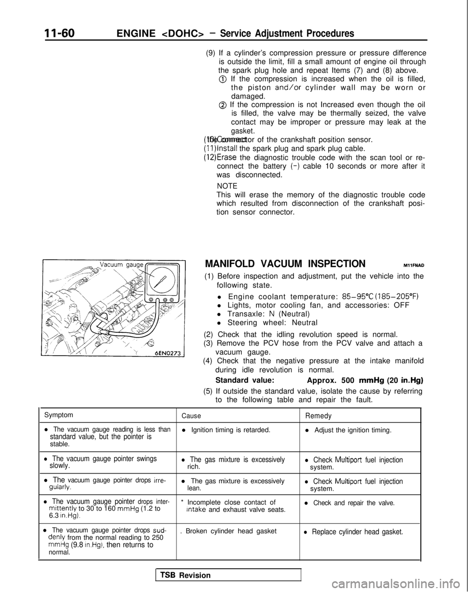
(3) Remove the PCV hose from the PCV valve and attach a
vacuum gauge.
(4) Check that the negative pressure at the intake manifold
during idle revolution is normal.
Standard value: Approx. 500 mmHg
(20 in.Hg)
(5) If outside the standard value, isolate the cause by referring to the following table and repair the fault.
Symptom
CauseRemedy
l The vacuum gauge reading is less thanstandard value, but the pointer isl Ignition timing is retarded. l Adjust the ignition timing.
stable.
l The vacuum gauge pointer swings
slowly.l The gas mixture is excessivelyrich.l Check Multiport fuel injectionsystem.
l The vacuum gauge pointer drops irre- gularly.
l The gas mixture is excessively
lean.l Check Multiport
fuel injectionsystem.
l The vacuum gauge pointer drops inter-mittently to 30 to 160 mmHg
(1.2 to * Incomplete close contact of Intake
and exhaust valve seats.l Check and repair the valve.
6.3 in.Hg).
l The vacuum gauge pointer drops sud- denly
from the normal reading to 250 . Broken cylinder head gasketl Replace cylinder head gasket.
mmHg (9.8 in.Hg), then returns tonormal.
TSB Revision
Page 249 of 1273
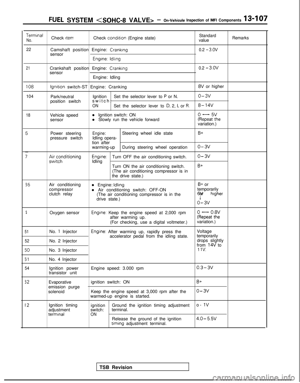
FUEL SYSTEM
TerminalCheck ItemCheck condition
(Engine state)StandardNo.valueRemarks
22
Camshaft position Engine: Cranking0.2 - 3.ov
sensor
Engrne: ldllng
21Crankshaft position Engine: Crankingsensor
Engine: Idling0.2 - 3.ov
108
104
18
lgnrtron switch-ST Engine: Cranking 8V
or higher
Park/neutral Ignition
Set the selector lever to
P or N.o-3v
position switch switch
:
ONSet the selector lever to D, 2, L or R.8- 14V
Vehicle speed
l Ignition switch: ON
sensor l Slowly run the vehicle forwardkeFaF:hevariation.)
Power steering
pressure switch
;;ir;z;ditioning
Engine:Steering wheel idle state
Idling opera-
tion after
warming-up During steering wheel operation
Engrne:Turn OFF the air conditioning switch.
Idling
Turn ON the air conditioning switch.(The air conditioning compressor is in
the drive state.)
B+
o-3v
o-3v
B+
35
1
51
52
50
51
54
Air conditioning
compressor
clutch relay
Oxygen sensor
No.
1 Injector
No. 2 Injector
No. 3 Injector
No. 4 Injector Ignition power
transistor unit l Engine: Idling
B+ or
l Air conditioning switch: OFF-ON temporarily
(The air conditioning compressor is in the 6V or
higher
drive state.)o’- 3v
Engine: Keep the engine speed at 2,000 rpm
after warming up. kQatot8h2:
(For checking, use a digital voltmeter.) variation.)
Engine: After warming up, rapidly press the
Voltage
accelerator pedal from the idling state. temporarily
drops slightly
from
14V to1 IV.
Engine speed: 3.000 rpm0.3- 3v
Evaporative
emission purge
solenoid ignition switch: ON
Keep the engine speed at 3,000 rpm after the
warmed-up engine is started.B+
o-3v
12Ignition timing
adjustment terminal
ignition
Ground the ignition timing adjustment o- 1vswitch:
terminal.ONRelease the ground of the ignition4.0- 5.W timing
adjustment terminal.
TSB Revision
Page 276 of 1273
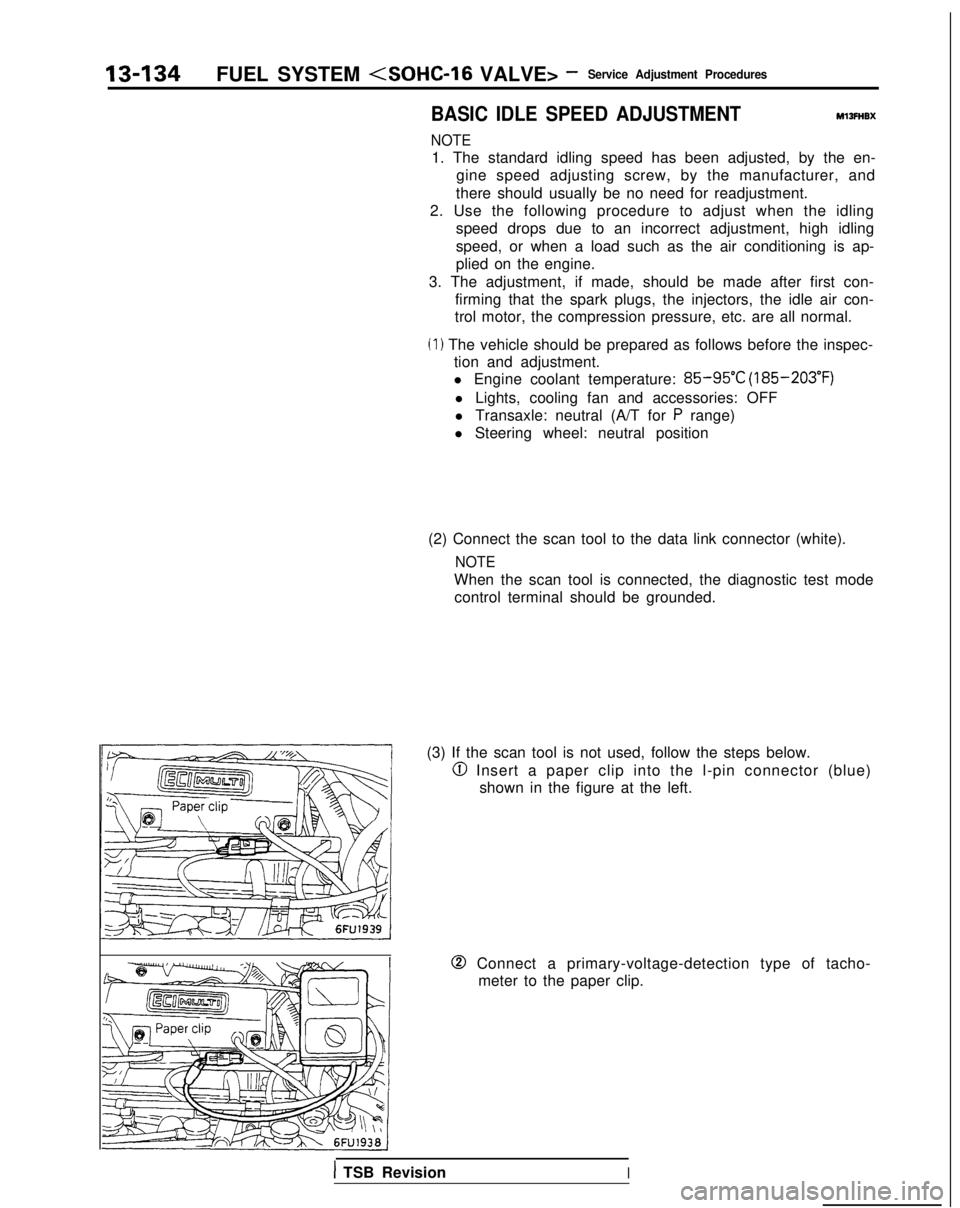
13-134FUEL SYSTEM (SOHC-16 VALVE> -Service Adjustment Procedures
BASIC IDLE SPEED ADJUSTMENTMlIFHBX
NOTE
1. The standard idling speed has been adjusted, by the en-
gine speed adjusting screw, by the manufacturer, and
there should usually be no need for readjustment.
2. Use the following procedure to adjust when the idling speed drops due to an incorrect adjustment, high idling
speed, or when a load such as the air conditioning is ap-
plied on the engine.
3. The adjustment, if made, should be made after first con- firming that the spark plugs, the injectors, the idle air con-
trol motor, the compression pressure, etc. are all normal.
(I ) The vehicle should be prepared as follows before the inspec- tion and adjustment.
l Engine coolant temperature:
85-95°C (185-203°F)
l Lights, cooling fan and accessories: OFF
l Transaxle: neutral (A/T for
P range)
l Steering wheel: neutral position
(2) Connect the scan tool to the data link connector (white).
NOTE
When the scan tool is connected, the diagnostic test mode control terminal should be grounded.
(3) If the scan tool is not used, follow the steps below.
@I Insert a paper clip into the l-pin connector (blue) shown in the figure at the left.
0 Connect a primary-voltage-detection type of tacho-meter to the paper clip.
1 TSB RevisionI
Page 657 of 1273
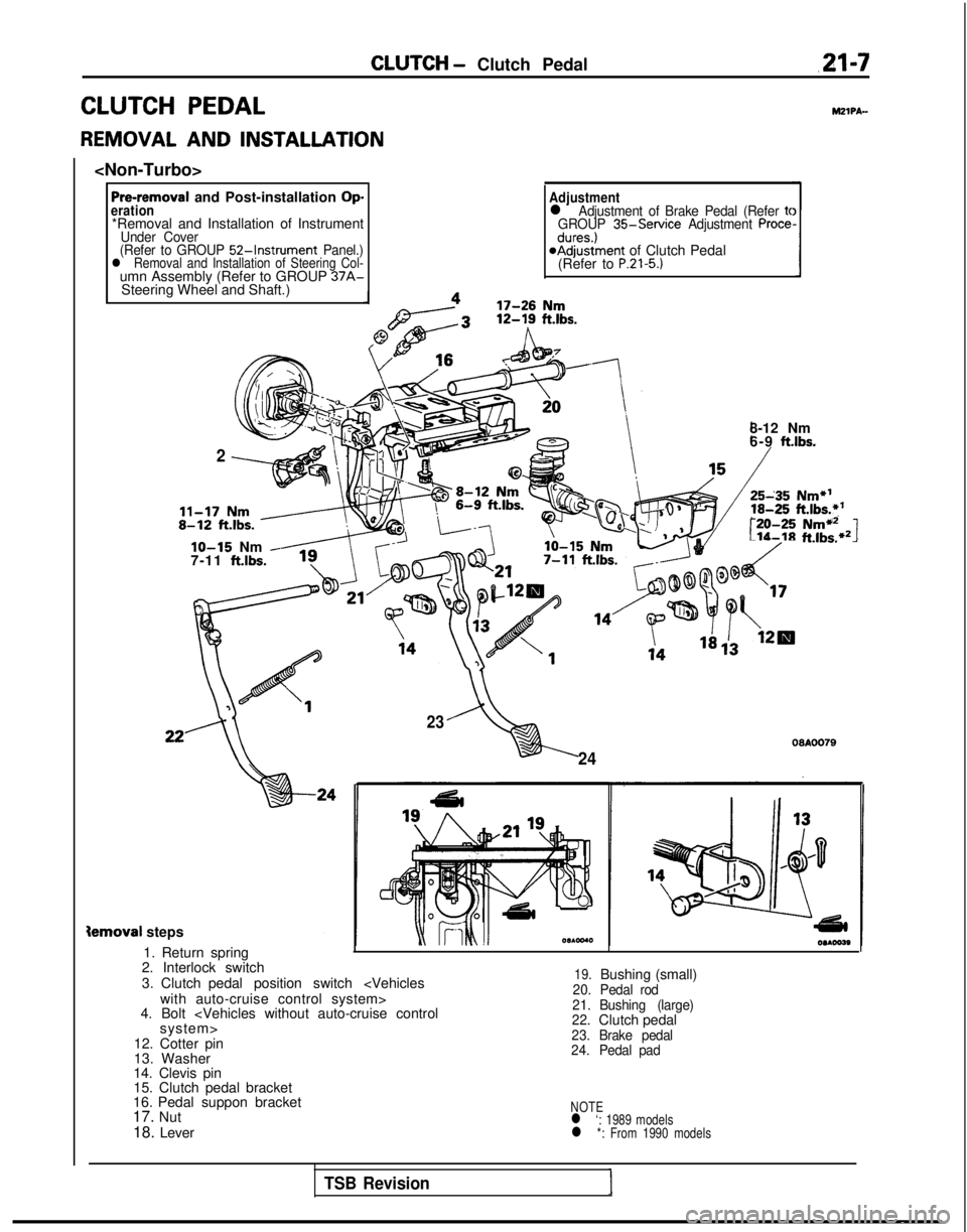
CLUTCH - Clutch Pedalm-7
CLUTCH PEDAL
REMOVAL AND INSTALLATION
Pre-removal and Post-installation Operation*Removal and Installation of InstrumentUnder Cover
(Refer to GROUP 52-Instrument Panel.)l Removal and Installation of Steering Col-umn Assembly (Refer to GROUP 37A-Steering Wheel and Shaft.)
Adjustmentl Adjustment of Brake Pedal (Refer tcGROUP 35-Service Adjustment Procedures.)@Adjustment of Clutch Pedal
(Refer to P.21-5.)
MZIPA-
2
8-12 Nm
6-9 ft.lbs.
r:-20-25Nmi12Lib-18ft.lbs.*21lo-15 Nm -7-11 ftlbs.
23
24
09AOO79
Semoval steps
1. Return spring
2. Interlock switch
3. Clutch pedal position switch
4. Bolt
12. Cotter pin
13. Washer
14. Clevis pin
15. Clutch pedal bracket
16. Pedal suppon bracket
17. Nut
18. Lever
19.Bushing (small)20. Pedal rod
21.
22. Bushing (large)
Clutch pedal23.
Brake pedal
24. Pedal pad
NOTEl ‘: 1989 modelsl *: From 1990 models
TSB Revision