1989 MITSUBISHI GALANT seats
[x] Cancel search: seatsPage 60 of 1273

II-IOENGINE
(3) Remove the PCV hose from the PCV valve and attach a
vacuum gauge.
(4) Check that the negative pressure at the intake manifold
during idle revolution is normal.
Standard value:
(8 VALVE>Approx. 500 mmHg (20 in.Hg)
<16VALVE>Approx. 510 mmHg (20 in.Hg)
(5) If outside the standard value, isolate the cause by referring
to the following table and repair the fault.
Symptom
CauseRemed
y
l The vacuum gauge reading is less than l Ignition timing is retarded.l Adjust the ignition timing.
standard value, but the pointer is
stable.
l The vacuum gauge pointer swings l The gas mixture is excessivelyl Check
Multiport Fuel Injection
slowly.rich.system.
l The vacuum gauge pointer drops irre-
l The gas mixture is excessively
l Check
Multiport Fuel Injectiongularly.lean.system.
l The vacuum gauge pointer drops inter-
0 Incomplete close contact of in-0 Check and repair the valve.mittently to 30 to 160
mmHg
(1.2 to take and exhaust valve seats.
6.3 in.Hg).
l The vacuum gauge pointer drops sud-l Broken cylinder head gasketl ,Replace cylinder head gasket. denly
from the normal reading to 250 mmHg
(9.8 in.Hg). then returns to
normal.
/ OlR0175
condition.
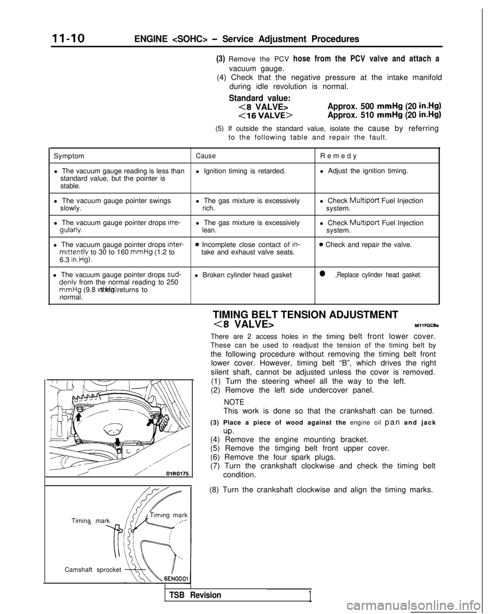
Timina mark
‘timing mark._*-
Camshaft sprocket TIMING BELT TENSION ADJUSTMENT
(8 VALVE>MllFGCEa
There are 2 access holes in the timing belt front lower cover.
These can be used to readjust the tension of the timing belt by
the following procedure without removing the timing belt front lower cover. However, timing belt “B”, which drives the right
silent shaft, cannot be adjusted unless the cover is removed. (1) Turn the steering wheel all the way to the left.
(2) Remove the left side undercover panel.
NOTE
This work is done so that the crankshaft can be turned.
(3) Place a piece of wood against the engine oil pan and jac
k
up.(4) Remove the engine mounting bracket.
(5) Remove the timging belt front upper cover.
(6) Remove the four spark plugs.
(7) Turn the crankshaft clockwise and check the timing belt
(8) Turn the crankshaft clockwise and align the timing marks.
TSB Revision1
Page 110 of 1273

II-60ENGINE
(9) If a cylinder’s compression pressure or pressure differenceis outside the limit, fill a small amount of engine oil through
the spark plug hole and repeat Items (7) and (8) above.
@ If the compression is increased when the oil is filled, the piston
and/or cylinder wall may be worn or
damaged.
@ If the compression is not Increased even though the oil is filled, the valve may be thermally seized, the valve
contact may be improper or pressure may leak at the
gasket. (10)Connect the connector of the crankshaft position sensor.
(1l)lnstall
the spark plug and spark plug cable.
(12)Erase the diagnostic trouble code with the scan tool or re-
connect the battery (-)
cable 10 seconds or more after it
was disconnected.
NOTE
This will erase the memory of the diagnostic trouble code which resulted from disconnection of the crankshaft posi-
tion sensor connector.
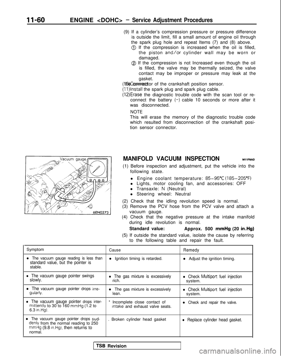
MANIFOLD VACUUM INSPECTION MllFNAD
(1) Before inspection and adjustment, put the vehicle into the following state.
l Engine coolant temperature:
85-95°C (185-205°F)
l Lights, motor cooling fan, and accessories: OFF
l Transaxle:
N (Neutral)
l Steering wheel: Neutral
(2) Check that the idling revolution speed is normal.
(3) Remove the PCV hose from the PCV valve and attach a
vacuum gauge.
(4) Check that the negative pressure at the intake manifold
during idle revolution is normal.
Standard value: Approx. 500 mmHg
(20 in.Hg)
(5) If outside the standard value, isolate the cause by referring to the following table and repair the fault.
Symptom
CauseRemedy
l The vacuum gauge reading is less thanstandard value, but the pointer isl Ignition timing is retarded. l Adjust the ignition timing.
stable.
l The vacuum gauge pointer swings
slowly.l The gas mixture is excessivelyrich.l Check Multiport fuel injectionsystem.
l The vacuum gauge pointer drops irre- gularly.
l The gas mixture is excessively
lean.l Check Multiport
fuel injectionsystem.
l The vacuum gauge pointer drops inter-mittently to 30 to 160 mmHg
(1.2 to * Incomplete close contact of Intake
and exhaust valve seats.l Check and repair the valve.
6.3 in.Hg).
l The vacuum gauge pointer drops sud- denly
from the normal reading to 250 . Broken cylinder head gasketl Replace cylinder head gasket.
mmHg (9.8 in.Hg), then returns tonormal.
TSB Revision
Page 988 of 1273

ACTIVE-ELECTRONIC CONTROL SUSPENSION - Troubleshooting 33B-49
Diagnostic
If, because of damage or disconnection of the heavy-line below. Note, however, this diagnostic signal is given if
circuit, or a malfunction of the rear-pressure sensor, etc., there is an overload.
a htgher than normal value of the internal pressure of the
l :1989 models
air springs is indicated continuously, the alarm light The alarm light does not illuminate for 1990, 1991,
illuminates*, and control is as described in the table 1992, 1993 models.
I1
Damping forceVehicle-heightSwitch acceptanceDiagnostic No.Attitude controlcontrol
control
HIGH 1 SPORT 1 AUTO 1 SOFT
25Control stopNormal
Only the vehicle-height
increase Not Accept
operation control function stops. accept
I
1990, 1991, 1992, HIGH-AUTO change possible. If the above diagnostic num\
ber is detected, the damping force that is
1993 models:the base of the SOFT mode and AUTO mode changes to the MEDIUM damping fo\
rce.
Service data indication
1 Code No. 1Indication
Standard valueDisplay
25Rear-pressure sensor output Fluctuates within a range of 0.5V
to 4.5V
25; RR. PRESS. SNSR. 2.45V
voltage when the body is shaken from side to side.
Condition
Reference value
Front seats: 2 persons When HIGH vehicle height
When NORMAL vehicle height
When LOW vehicle
height
1.6OV
0.9ov 0.86V
ECU terminal voltages (when connector is connected) ConditionTerminal
voltage
25Power supply for sensor
37Rear air spring pressure signal When the ECU is activated
Low rear air spring pressure
High rear air spring pressure
5v
0.5vI
4.5v
When wiring IS damaged or disconnected5v
35 Sensor circuit ground
Constantly o
v
Checking the rear-pressure sensor (with the connector disconnected)
Terminal Connection destination or MeasurementNomeasured part
Tester connection
Check condition
Standard
ERear-pressure sensorResistance
25-35 Constantly Approx.
All resistances 5 kll
37Rear-pressure sensor
Resistance
37-35 Change should be smooth (accordingO-5 klloutput to the air pressure applied to the rear
-pressure sensor) within the standard
value range shown at the right
Troubleshooting hints (mechanical malfunctions) Malfunctionmode Malfunction probable cause
Malfunction
Note
Harness
short-circuit Because of a short-circurt
of the harness, etc , Insufficient control of the attitude, resulting in a
-no correction of the air-supply and exhaust time feeling of incompatibility
can be made to compensate for a loaded
condition of the vehicle. Air leakage
Wear, damage, etc. of the O-ring
Vehicle height decreases if not corrected-
TSB Revision