1989 MITSUBISHI GALANT fuel filter
[x] Cancel search: fuel filterPage 3 of 1273
00-l
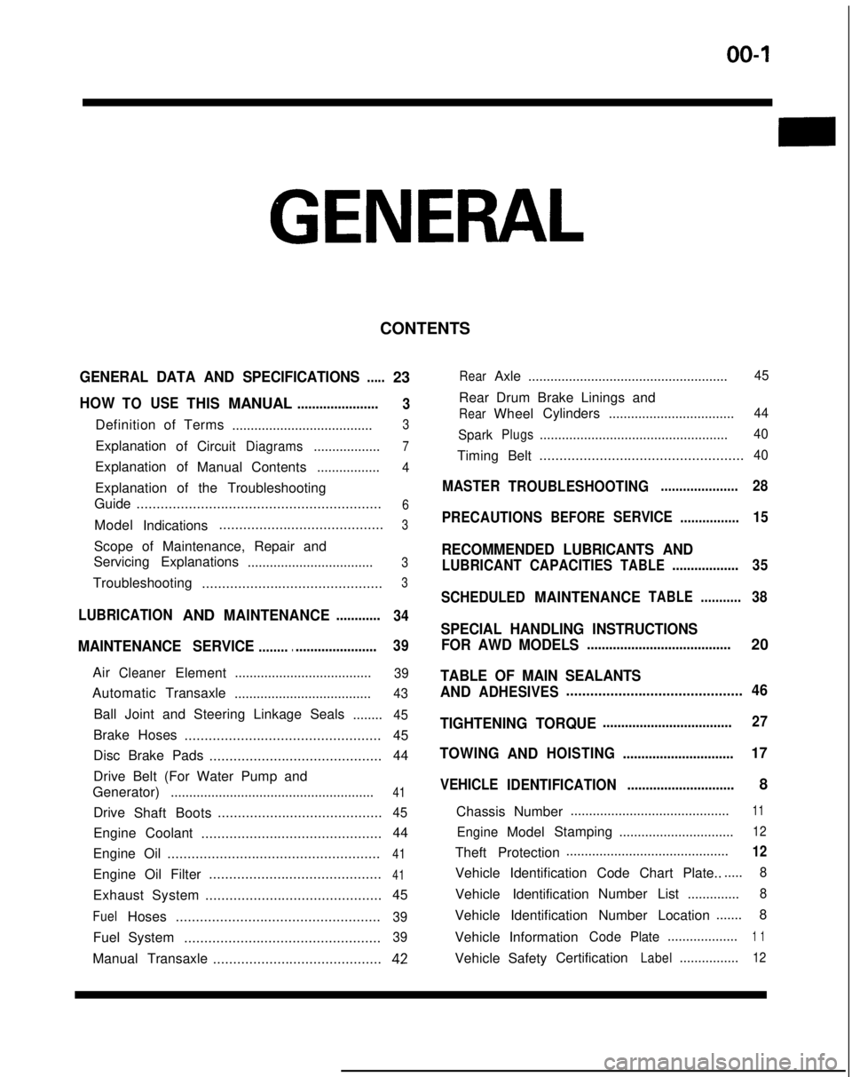
GENERAL
CONTENTS
GENERAL DATA AND SPECIFICATIONS.....23
HOWTOUSETHISMANUAL......................
3
Definition of Terms ......................................3
ExplanationofCircuitDiagrams..................7
Explanation of
ManualContents .................4
Explanation of the Troubleshooting
Guide .............................................................
6
Model
Indications .........................................3
Scope of Maintenance, Repair and
Servicing Explanations
..................................
3
Troubleshooting .............................................3
LUBRICATIONANDMAINTENANCE............
34
MAINTENANCE SERVICE............................... 39
AirCleanerElement
.....................................39
Automatic
Transaxle
.....................................43
Ball Joint and Steering Linkage Seals ........45
Brake Hoses................................................. 45
Disc Brake Pads ........................................... 44
Drive Belt (For Water Pump and
Generator) .......................................................
41
Drive
Shaft Boots .........................................45
Engine Coolant
............................................. 44
Engine Oil .....................................................
41
Engine Oil Filter ...........................................41
Exhaust System
............................................ 45
FuelHoses
...................................................39
Fuel System
.................................................39
Manual Transaxle ..........................................42
RearAxle......................................................45
Rear Drum Brake Linings and
RearWheel Cylinders
..................................44
Spark
Plugs...................................................40
Timing Belt...................................................40
MASTER
TROUBLESHOOTING.....................28
PRECAUTIONS
BEFORESERVICE................15
RECOMMENDED LUBRICANTS AND
LUBRICANT CAPACITIESTABLE..................35
SCHEDULED
MAINTENANCETABLE ...........38
SPECIAL HANDLING INSTRUCTIONS
FOR AWD MODELS
.......................................20
TABLE OF MAIN SEALANTS
AND
ADHESIVES ............................................46
TIGHTENING TORQUE
................................... 27
TOWING
ANDHOISTING ..............................17
VEHICLE
IDENTIFICATION .............................8
Chassis Number ...........................................
11
EngineModel
Stamping
...............................12
Theft Protection ............................................12
Vehicle Identification Code Chart Plate.......
8
Vehicle Identification Number List
..............8
Vehicle Identification Number Location .......
8
Vehicle Information
CodePlate...................1 1
Vehicle SafetyCertificationLabel................12
Page 38 of 1273
00-36
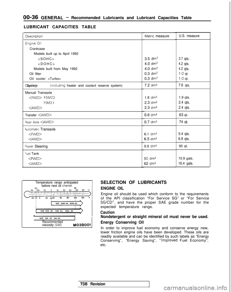
GENERAL -Recommended Lubricants and Lubricant Capacities Table
LUBRICANT CAPACITIES TABLE
Descrrptron
Engrne 011
Crankcase
Models built up to April 1992
Models built from May 1992
Oil filter
Oil cooler
(rncludrng heater and coolant reserve system)
Manual Transaxle
F5M3
1
Transfer
qear Axle
4utomatrc Transaxle
‘ower Steering %el
Tank
Metric measure
3.5 dm3
4.0 dm3
4.0 dm3
0.3 dm3
0.3 dm3
7.2 dm3
1.8 dm31.9 qts.
2.3
dm32.4 qts.
2.3 dm32.4 qts.
3.6 dm363 qt.
3.7
dm374 qt.
6.1 dm3
6.5 dms
3.9 dm3 60
dm3
62 dm3
U.S. measure
3.7qts.
4.2qts.
4.2qts.
1 I2qt.
1 I2qt.
7.6qts.
5.4 qts.
6.9 qts.
95 qt.
15.9 gals.
16.4 gals.
Temperature range anticipated before next oil chanae
SAE SW-30 SW-40IRecommendedviscosity (SAE) M03BOOl
SELECTION OF LUBRICANTS
ENGINE OIL
Engine oil should be used which conform to the requirements
of the API classification “For Service SG” or “For Service
SGKD”, and have the proper SAE grade number for the
expected temperature range.
Caution
Nondetergent or straight mineral oil must never be used.
Energy Conserving Oil
In order to improve fuel economy and conserve energy new,
lower friction engine oils have been developed. These oils are readily available and can be identified by such labels as “Energy
Conserving”, “Energy Saving”,
“Improved Fuel Economy”,
etc.
TSB Revision
Page 40 of 1273
00-38GENERAL- Scheduled Maintenance Table
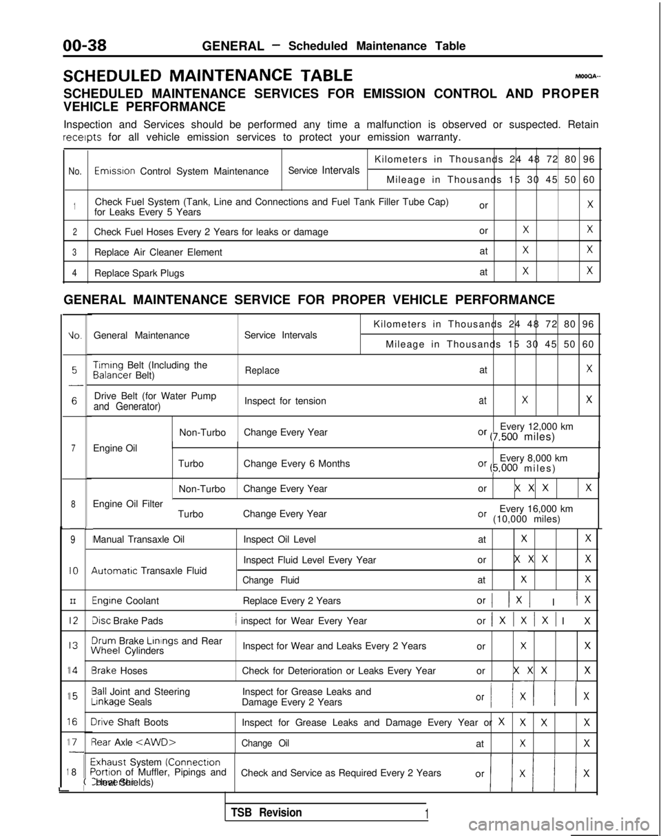
SCHEDULED MAINTENANCE
TABLEMOOOA-
SCHEDULED MAINTENANCE SERVICES FOR EMISSION CONTROL AND PROPER
VEHICLE PERFORMANCE
Inspection and Services should be performed any time a malfunction is ob\
served or suspected. Retain receipts
for all vehicle emission services to protect your emission warranty.
Kilometers in Thousands 24 48 72 80 96
No.Emwsron Control System MaintenanceService IntervalsMileage in Thousands 15 30 45 50 60
1Check Fuel System (Tank, Line and Connections and Fuel Tank Filler Tube\
Cap) orXfor Leaks Every 5 Years
2Check Fuel Hoses Every 2 Years for leaks or damage orXX
3Replace Air Cleaner ElementatXX
4Replace Spark PlugsatXX
GENERAL MAINTENANCE SERVICE FOR PROPER VEHICLE PERFORMANCE
L
1
1
1
1
1
i
IO.General Maintenance
Service Intervals
7Engine Oil
8
9
IO
III2
I3
14
15
I6
I71
8
L
I
I
I
I
I\
I
II
I
I
;(
Kilometers in Thousands 24 48 72 80 96
Mileage in Thousands 15 30 45 50 60 Timing
Belt (Including the Balancer
Belt)
ReplaceatX
Drive Belt (for Water Pump
Inspect for tensionatXXand Generator)
Non-TurboChange Every Year Every 12,000 kmOr (7,500 miles)
Turbo Change Every 6 Months Every 8,000 km
Or (5.000 miles
)
II
Non-Turbo
Change Every Year or X X XX
Every 16,000 kmOr (10,000 miles)
Engine Oil Filter
TurboChange Every Year
Manual Transaxle Oil 4utomatrc
Transaxle Fluid Inspect Oil Level
at
XX
Inspect Fluid Level Every Yearor X X XX
Change FluidatXX
Engine Coolant
Replace Every 2 YearsOrI 1x1 I IX
Disc Brake Pads1 inspect for Wear Every Yearor/XlXlXl I
X
3rum
Brake Linings
and Rear iNheel
Cylinders Inspect for Wear and Leaks Every 2 Years
or
XX
3rake HosesCheck for Deterioration or Leaks Every Year or X X XX
3all Joint and SteeringInspect for Grease Leaks and-inkage
Seals
Damage Every 2 Years
Or I/ XII x
Irive Shaft Boots Inspect for Grease Leaks and Damage Every Year or XXXX
3ear Axle
Exhaust System (Connectron>ortion of Muffler, Pipings and
Check and Service as Required Every 2 YearsConverter Heat Shields)
TSB Revision1
Page 41 of 1273
GENERAL - Scheduled Maintenance Table/Maintenance Service00-39
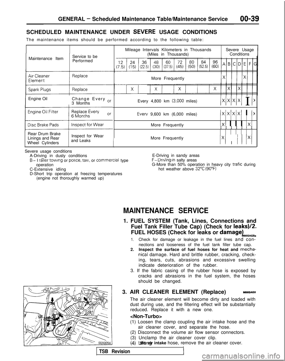
SCHEDULED MAINTENANCE UNDER SEVEiRE USAGE CONDITIONS
The maintenance items should be performed according to the following tab\
le:
Maintenance Item Service to be
Performed
IEngine Oil Change Every or
3 Months
(:z:.:a::I
Rear Drum Brake
Linings and Rear
Wheel Cylinders Inspect for Wear
and Leaks
1
Mileage Intervals Kilometers in Thousands (Miles in Thousands) Severe Usage
Conditions
More Frequently
Every 4,800 km
(3,000 miles)/xlxlx/xI I I1 Every
9,600 km (6,000 miles)
IxIxlxIxI I I>(
More Frequently1x1 I I I 1x1I I I I I I I
More Frequently
Ix1 I I I lx/
Severe usage conditions A-Driving in dusty conditions
- -B- I railer
towing or police.
taxi,
or commercial
type
operation
C-Extensive idling
D-Short trip operation at freezing temperatures (engine not thoroughly warmed up) E-Driving in sandy areas- -..F-Dnvlng In salty areas
G-More than 50% operation in heavy city trafic during
hot weather above 32°C (90°F)
MAINTENANCE SERVICE
1. FUEL SYSTEM (Tank, Lines, Connections and
Fuel Tank Filler Tube Cap) (Check for leaks)/2.
FUEL HOSES (Check for leaks or
damagekOOSnOB.
1.Check for damage or leakage in the fuel lines and con-
nections and looseness of the fuel tank filler tube cap.
2. Inspect the surface of fuel hoses for heat and mecha-
nicall damage. Hard and brittle rubber, cracking, check-
ing, tears, cuts, abrasions and excessive swelling
indicate deterioration of the rubber.
3. If the fabric casing of the rubber hose is exposed by cracks and abrasions in the fuel system, the hoses
should be changed.
3. AIR CLEANER ELEMENT (Replace)
MMlSAKH
The air cleaner element will become dirty and loaded with dust during use, and the filtering effect will be substantiallyreduced. Replace it with a new one.
(1) Loosen the clamp coupling the air intake hose and the air cleaner cover, and separate the hose.
(2) Disconnect the volume air flow sensor connectors.
(3) Unclamp the air cleaner cover clip.
(4) Lifting the air intake hose, remove the air cleaner cover.
TSB Revision1
Page 143 of 1273
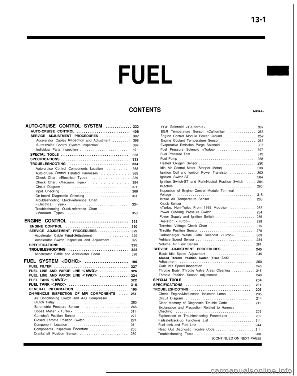
13-1
FUEL
CONTENTSM’ISAA--
AUTO-CRUISE CONTROL SYSTEM.............
.
332
AUTO-CRUISE CONTROL ............................. 408
SERVICE ADJUSTMENT PROCEDURES .................397
Accelerator Cables
inspectron and Adjustment ........
.
398 Auto-cruise
Control System Inspection
..............397
Individual Parts Inspection ......................
401SPECfAL
TOOLS
.....................................
333
SPECIFICATIONS .................................... 332
TROUBLESHOOTING ................................. 334
Auto-cruise Control Components Location ..........368
Auto-cruise Control
Related Harnesses
..........365
Check Chart
Check Chart
Circuit Diagram ................................
371input Checking................................
.
366
On-board Diagnostic Checking ......................
361Troubleshooting Quick-reference Chart
.
334
Troubleshooting Quick-reference Chart
ENGINE CONTROL...............................
.
328
ENGINE CONTROL ..................................
330
SERVICE ADJUSTMENT PROCEDURES .................329
Accelerator Cable inspectron and Adjustment
...........329
Accelerator Switch Inspection and Adjustment ..........329
SPECIFICATIONS ....................................
328
TROUBLESHOOTlNG................................
.
328
Accelerator
Cable and Accelerator Pedal .............
.
328
FUEL SYSTEM
FUEL FILTER .........................................
327
FUEL LINE AND VAPOR LINE
.
326
FUEL LINE AND VAPOR LINE
.
324
FUEL TANK
.
322
FUELTANK
.
318
GENERAL INFORMATION ............................ 196
ON-VEHICLE INSPECTION OF MFI
COMPONENTS
......251
Air Conditioning Switch and A/C Compressor Clutch Relay .....................................
285
Barometric Pressure Sensor .................... 266
Boost Meter
311Camshaft Position Sensor ........................
.
277Closed Throttle Position Switch
.....................
.
274
Component Location .............................
251Components Inspection Pocedure
................. 255
Crankshaft Position Sensor ..................... 280EGR
Solenord
...................
.
307EGR Temperature Sensor
.............
.
288Engrne Control Module Power Ground
................
.
257
Engine Coolant Temperature Sensor ..................
268Evaporative Emission Purge Solenoid .................
.
307
Fuel Pressure Solenoid
307Fuel Pressure Test...............................
.
312
Fuel Pump ...................................... 258
Heated Oxygen Sensor ............................ 290
Idle Air Control Motor (Stepper Motor) ................
238Ignition Coil and Ignition Power Transistor .............
.
302
Ignition Switch-ST .................................. 284
Ignition Switch-ST and Park/Neutral Position Switch .....284
Injectors .......................................
295Inspection of Engine Control Module Terminal
Voltage .......................................
.
315
Intake Air Temperature Sensor .......................263
Knock Sensor
Power Steering Pressure Switch ......................
284Power Supply and Ignition Switch ...................
.
255Resistor
..............................
.
298Terminal Voltage Check Chart
......................
.
315Throttle Position Sensor
..........................
.
270Turbocharger Waste Gate Solenoid
.........
.
309 Vehicle
Speed Sensor
............................... 284
Volume Air Flow Sensor ............................
261SERVICE ADJUSTMENT PROCEDURES ...............
.
245
Basic
idle Speed Adjustment .......................
.
245
Closed Throttle Position Switch (Fixed
SAS)Adjustment ......................................
.
250
Curb
Idle Speed Inspection
..........................245Throttle Body (Throttle Valve Area) Cleaning
...........
.
248Throttle Position Sensor Adjustment
..................
.
248
SPECIALTOOLS...................................
.
204
SPECIFICATIONS ...................................
201TROUBLESHOOTING ...............................
.
205
Check Engine/Malfunction Indicator Lamp ..............205
Circuit Diagram .................................... 214
Clear Memory of Diagnostic Trouble Code .............
211Explanation and Precaution Related to Harness
Checking ......................................
.
205Explanation of Troubleshooting Procedures
............
.
205Failsafe/Back-up Functions List
.....................
.
211Fuel tank and Fuel Line
............................
.
244
Read Out Diagnostic Trouble Code ...................
211Troubleshooting Table
.............................
.
208(CONTINUED ON NEXT PAGE)
Page 144 of 1273
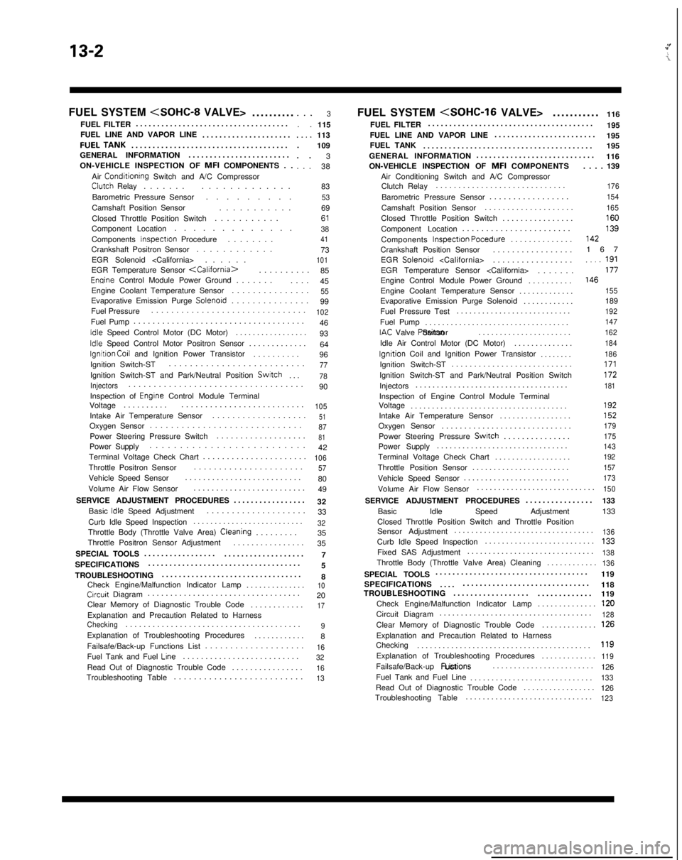
13-2
FUEL SYSTEM
..........
FUEL FILTER ....................................
FUEL LINE AND VAPOR LINE .....................FUELTANK....................................
.
GENERAL INFORMATION ........................
ON-VEHICLE INSPECTION OF MFI
COMPONENTS . .
Air
Conditionrng Switch and A/C CompressorClutch Relay ......
.
.............
Barometric Pressure Sensor .........
Camshaft Position Sensor ...........
Closed Throttle Position Switch ...........
Component Location .............
Components
Inspectron Procedure .......
.
Crankshaft Positron Sensor ............
EGR Solenoid
. . .3. .
115..,.113
. 109
. . 3
. . . 38
83
536961384173101EGR Temperature Sensor
.
85
Enqine Control Module Power Ground ......
.
....
45
Engine Coolant Temperature Sensor ...............
55Evaporative Emission Purge Solenord..............
.
99
Fuel Pressure ...............................
102Fuel Pump
...................................
.
46
Idle Speed Control Motor (DC Motor) ................
.
93
Idle Speed Control Motor Positron Sensor ............
.
64
lgnitron Co11 and Ignition Power Transistor .........
.
96
Ignition Switch-ST ..........................
77Ignition Switch-ST and Park/Neutral Position Switch
...78
Injectors..................................
.
90
Inspection of
Engrne Control Module Terminal
Voltage .........
.
..........................
105Intake Air Temperature Sensor ..................
.
51Oxygen Sensor
............................
.
87Power Steering Pressure Switch
..................
.
81Power Supply
.........................
.
42
Terminal Voltage Check Chart ......................
106Throttle Positron Sensor.....................
.
57Vehicle Speed Sensor
.........................
.
80
Volume Air Flow Sensor .........................
49
SERVICE ADJUSTMENT PROCEDURES .................
32
Basic
Idle Speed Adjustment ...................
.
33
Curb Idle Speed Inspection ..........................
32Throttle Body (Throttle Valve Area) Cleaning........
.
35
Throttle Positron Sensor Adjustment ................
35
SPECIAL TOOLS 7
.................
...................
SPECIFICATIONS ....................................
5
TROUBLESHOOTING .................................
8
Check Engine/Malfunction Indicator Lamp ..............
10Crrcuit Diagram.................................
.
20
Clear Memory of Diagnostic Trouble Code ............
17Explanation and Precaution Related to HarnessChecking......................................
.
9Explanation of Troubleshooting Procedures
...........
.
8
Failsafe/Back-up Functions List ....................
16Fuel Tank and Fuel Lrne.........................
.
32Read Out of Diagnostic Trouble Code
...............
.
16Troubleshooting Table
.........................
.
13
FUEL SYSTEM
116
FUEL FILTER .......................................
195
FUEL LINE AND VAPOR LINE ........................
195
FUEL TANK ........................................ 195
GENERAL INFORMATION ............................
116
ON-VEHICLE INSPECTION OF MFI
COMPONENTS
Air Conditioning Switch and A/C Compressor Clutch Relay .............................
Barometric Pressure Sensor .................
Camshaft Position Sensor ....................
Closed Throttle Position Switch ................
Component Location .......................
Components Inspectron Pocedure
..............
Crankshaft Position Sensor .................
EGR Solenoid
EGR Temperature Sensor
Engine Control Module Power Ground ..........
Engine Coolant Temperature Sensor .............
Evaporative Emission Purge Solenoid ............
Fuel Pressure Test ...........................
Fuel Pump ..................................
IAC Valve Positon Sensor
......................
Idle Air Control Motor (DC Motor) ..............
lgnrtion Coil and Ignition Power Transistor
.......
.
Ignition Switch-ST ...........................
Ignition Switch-ST and Park/Neutral Position Switch
Injectors ....................................
Inspection of Engine Control Module Terminal
Voltage .....................................
Intake Air Temperature Sensor .................
Oxygen Sensor .............................
Power Steering Pressure
Swatch..............
.
Power Supply ...............................
Terminal Voltage Check Chart ..................
Throttle Position Sensor .......................
Vehicle Speed Sensor ......................... . . . . 139
176
154
165
16013914216
7
..,_ 191177146
155
189192
147
162
184
186
171172181
192152
179
175
143
192
157
173
Volume Air Flow Sensor ...........................
.
150
SERVICE ADJUSTMENT PROCEDURES
...............
.
133
Basic Idle Speed Adjustment 133
Closed Throttle Position Switch and Throttle Position
Sensor Adjustment .................................
136Curb Idle Speed Inspection
.........................
.
133Fixed SAS Adjustment
.............................
.
138Throttle Body (Throttle Valve Area) Cleaning
...........
.
136
SPECIAL TOOLS
...................................
.
119
SPECIFICATIONS 118
.... ..............................
TROUBLESHOOTING ..................
.............
119
Check Engine/Malfunction Indicator Lamp ..............
120Circuit Diagram...................................
.
128Clear Memory of Diagnostic Trouble Code
............
.
126Explanation and Precaution Related to Harness
Checking ........................................
.
119Explanation of Troubleshooting Procedures
............
.
119Failsafe/Back-up
Fuctions List
........................
126
Fuel Tank and Fuel Line .............................
133Read Out of Diagnostic Trouble Code ................
.
126
Troubleshooting Table ..............................
123
Page 146 of 1273
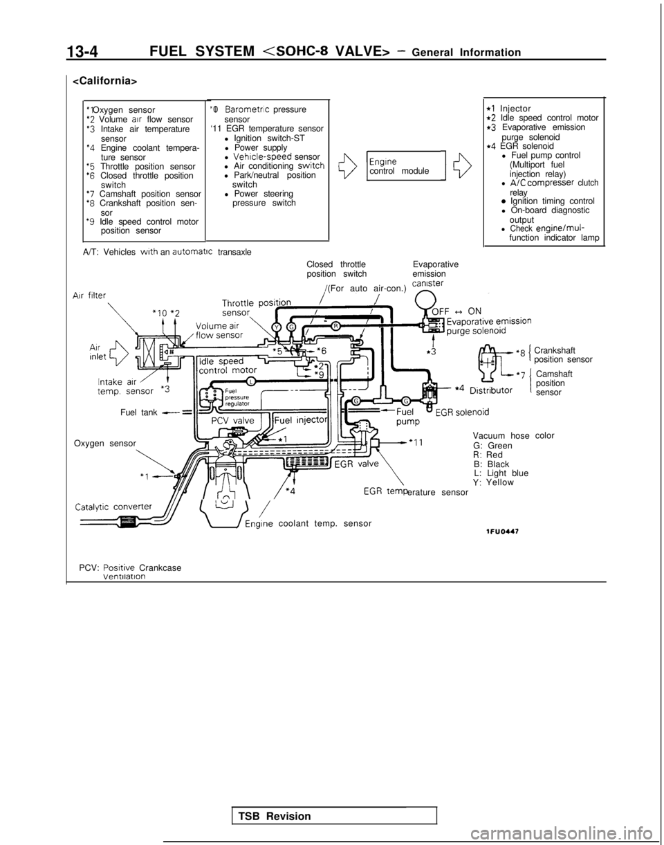
13-4FUEL SYSTEM
*2 Volume
air
flow sensor$3 Intake air temperature
sensor
*4 Engine coolant tempera-ture sensor
“5 Throttle position sensor‘6 Closed throttle position switch
*7 Camshaft position sensor*8 Crankshaft position sen-
sor
*9 Idle speed control motor position sensor “I 0
Barometric pressure
sensor
‘11 EGR temperature sensor
l Ignition switch-STl Power supply
l
Vehrcle-speed sensor
l Air conditioning switch
l Park/neutral position
switch
l Power steering pressure switchI13
Engrnecontrol module10
rl Injectort2 Idle speed control motorr3 Evaporative emission
purge solenoid
r4 EGR solenoidl Fuel pump control
(Multiport fuel
injection relay)
l A/C compresser clutchrelay0 Ignition timing control
l On-board diagnostic
output
l Check engine/muj-function indicator lamp
A/T: Vehicles
with an automatrc
transaxle
Closed throttleposition switch Evaporative
emission
/(For auto air-con.) can’ster
/ n
Vacuum hose
G: Green
R: Red
B: Black L: Light blue
Y: Yellow
erature sensor Air
filter
Fuel tank - =
Oxygen sensor
\ U /Eni coolant temp. sensor1FUO447
Crankshaft
position sensor
Camshaft
position
sensor
color
PCV: Posrtive
Crankcase
TSB Revision
Page 147 of 1273
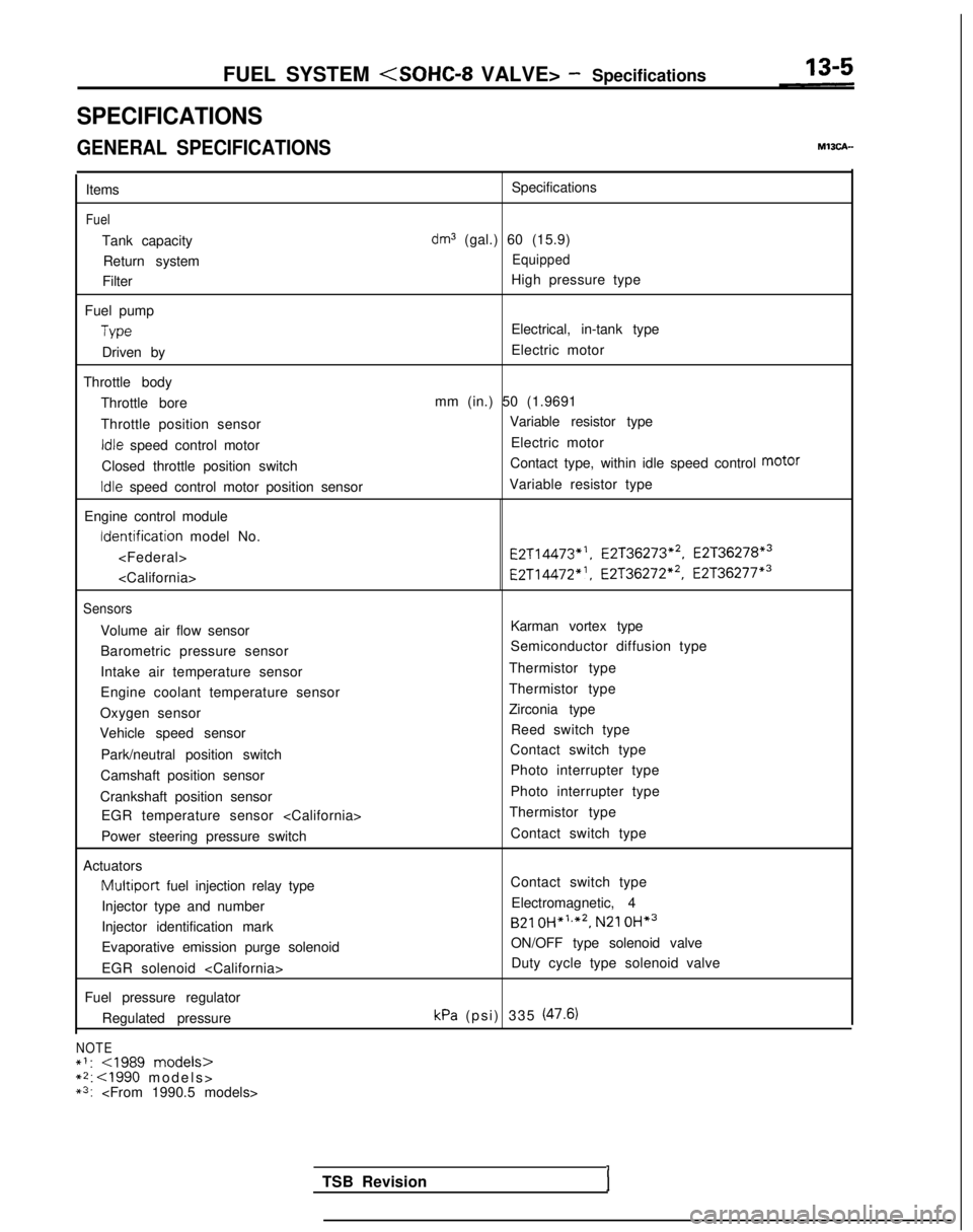
FUEL SYSTEM
SPECIFICATIONS
GENERAL SPECIFICATIONS
Items
Fuel
Tank capacity
Return system
Filter
Fuel pump
Type
Driven by
Throttle body Throttle bore
Throttle position sensor
Idle speed control motor
Closed throttle position switch
Idle speed control motor position sensor
Engine control module Identification
model No.
Sensors
Volume air flow sensor
Barometric pressure sensor
Intake air temperature sensor
Engine coolant temperature sensor
Oxygen sensor
Vehicle speed sensor
Park/neutral position switch
Camshaft position sensor
Crankshaft position sensor EGR temperature sensor
Power steering pressure switch
Actuators
Multiport fuel injection relay type
Injector type and number
Injector identification mark
Evaporative emission purge solenoid
EGR solenoid
Fuel pressure regulator Regulated pressure
NOTE*I:
*3:
dm3 (gal.) 60 (15.9)
Equipped
High pressure type
Electrical, in-tank type
Electric motor
mm (in.) 50 (1.9691 Variable resistor type
Electric motor
Contact type, within idle speed control motor
Variable resistor type E2T14473*‘,
E2T36273*2, E2T36278*3
E2T14472”. E2T36272*2, E2T36277*3
Karman vortex type
Semiconductor diffusion type
Thermistor type
Thermistor type
Zirconia type Reed switch type
Contact switch type
Photo interrupter type
Photo interrupter type
Thermistor type
Contact switch type
Contact switch typeElectromagnetic, 4
B21 OH*‘,*2,
N21 OH*3
ON/OFF type solenoid valve
Duty cycle type solenoid valve
kPa (psi) 335 (47.6)
TSB RevisionI