1989 MITSUBISHI GALANT weight
[x] Cancel search: weightPage 14 of 1273
GENERAL - Vehicle Identification
OOA0192
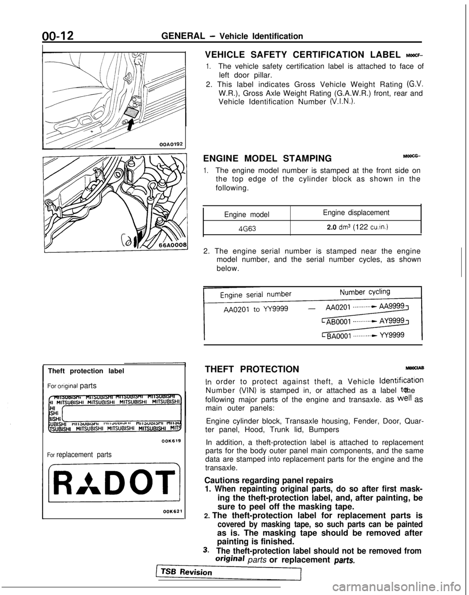
Theft protection label
For
orIgInal parts
OOK619
For replacement parts
OOK621
VEHICLE SAFETY CERTIFICATION LABEL MWCF-
1.The vehicle safety certification label is attached to face of left door pillar.
2. This label indicates Gross Vehicle Weight Rating
(G.V.
W.R.), Gross Axle Weight Rating (G.A.W.R.) front, rear and
Vehicle Identification Number
(V.I.N.).
ENGINE MODEL STAMPINGM6ocG-.
1.The engine model number is stamped at the front side on the top edge of the cylinder block as shown in the
following.
Engine model Engine displacement 4G63
2.0
dm3 (122 cu.in.)
2. The engine serial number is stamped near the engine
model number, and the serial number cycles, as shown
below.
THEFT PROTECTION
MwclA9
In order to protect against theft, a Vehicle ldentificatlon
Number
(VIN) is stamped in, or attached as a label to, the
following major parts of the engine and transaxle. as
well as
main outer panels:
Engine cylinder block, Transaxle housing, Fender, Door, Quar-
ter panel, Hood, Trunk lid, Bumpers
In addition, a theft-protection label is attached to replacement
parts for the body outer panel main components, and the same
data are stamped into replacement parts for the engine and the
transaxle.
Cautions regarding panel repairs
1. When repainting original parts, do so after first mask-
ing the theft-protection label, and, after painting, be
sure to peel off the masking tape.
2. The theft-protection label for replacement parts is
covered by masking tape, so such parts can be painted
as is. The masking tape should be removed after
painting is finished.
3.The theft-protection label should not be removed from
original parts or replacement par-&
Page 20 of 1273
00-l 8GENERAL - Towing and Hoisting
SAFETY PRECAUTIONS
The following precautions should be taken when towing thevehicle.
1.DO NOT LIFT OR TOW THE VEHICLE BY ATTACHING TO
OR WRAPPING AROUND THE BUMPER.
2. Any loose or protruding parts of damaged vehicle such as hoods, doors, fenders, trim, etc., should be secured prior to
moving the vehicle.
3.Operator should refrain from going under a vehicle while it
is lifted by the towing equipment, unless the vehicle in
adequately supported by satefy stands.
4. Never allow passengers to ride in a towed vehicle. 5. State and local rules and regulations must be followed when towing a vehicle.
Refer to the section “Special Handling Instructions for AWD
Models”.
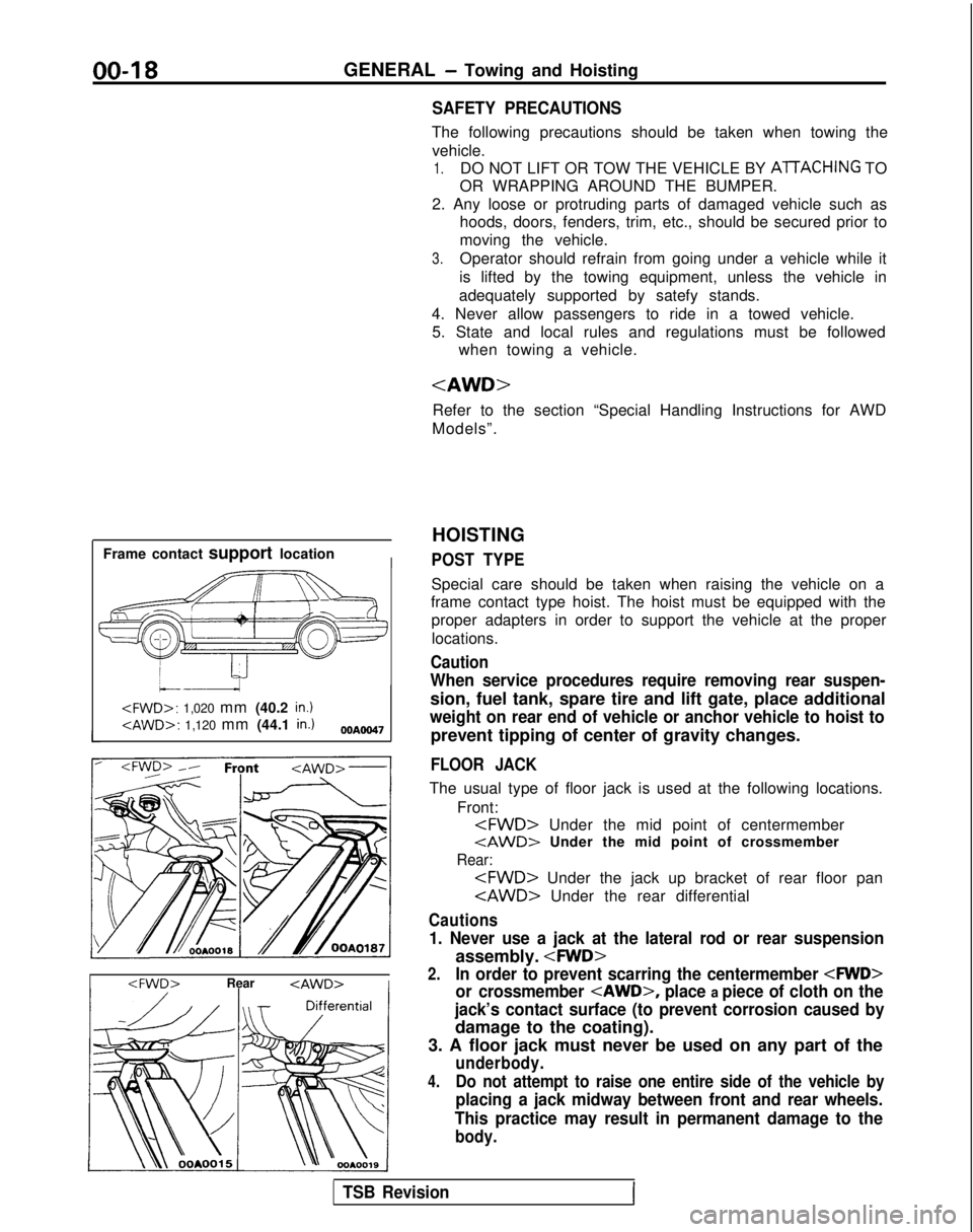
Frame contact support location
I
HOISTING
POST TYPE
Special care should be taken when raising the vehicle on a
frame contact type hoist. The hoist must be equipped with the
proper adapters in order to support the vehicle at the proper
locations.
Caution
When service procedures require removing rear suspen-
sion, fuel tank, spare tire and lift gate, place additional
weight on rear end of vehicle or anchor vehicle to hoist to
prevent tipping of center of gravity changes.
FLOOR JACK
The usual type of floor jack is used at the following locations.
Front:
tAWD> Under the mid point of crossmember
Rear:
Cautions
1. Never use a jack at the lateral rod or rear suspension
assembly.
2.In order to prevent scarring the centermember
or crossmember
place a piece of cloth on the
jack’s contact surface (to prevent corrosion caused by
damage to the coating).
3. A floor jack must never be used on any part of the
underbody.
4.Do not attempt to raise one entire side of the vehicle by
placing a jack midway between front and rear wheels.
This practice may result in permanent damage to the
body.
TSB RevisionI
Page 26 of 1273
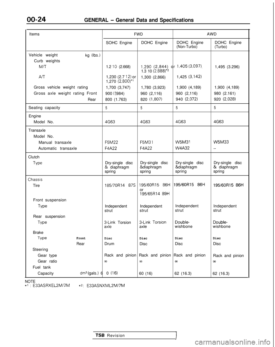
00-24GENERAL - General Data and Specifications
ItemsFWDAWD
SOHC Engine DOHC Engine DOHC Engine DOHC Engine
(Non-Turbo)
(Turbo)
Vehicle weight
kg (Ibs.)
Curb weightsMIT
1.2 10 (2.668)1.290 (2,844) or 1.405 (3.097).1,495 (3.296)1.3 10 (2.8881e2
/-v-r1,230 (2.7 12) or
1,300 (2,866) 1,425 (3.142)
1,270
(2.800)”
Gross vehicle weight rating 1,700 (3,747) 1,780 (3,923)1,900 (4,189)
1,900 (4,189)
Gross axle weight rating Front 900 (I ,984)
960 (2,116) 960 (2,116)
980 (2.161)
Rear800 (1.763)820 (1,807)940 (2.072)920 (2.028)
Seating capacity5 55 5
Engine
Model No.
4G634G63 4G634G63
Transaxle
Model No.Manual transaxle F5M22 F5M3
1 W5M31 W5M33
Automatic transaxle
F4A22F4A22 W4A32-
Clutch
Type
Dry-single disc
Dry-single disc
Dry-single disc Dry-single disc &
diaphragm & diaphragm & diaphragm &
diaphragm
spring spring spring
springChassis
Tire
185/7OR14 87s 195/60R15 86i-i 195/60R15 86ti195/60R15 86H
or
195/65R14 89H
Front suspension Type
Independent Independent
Independent
Independent
strut strut strut
strut
Rear suspension Type
3L$k Torsion3$k Torsion Double-
Double-
wishbone wishbone
Brake Type
Front
DiscDisc Disc
Disc
RearDrum
Disc Disc
Disc
Steering
Gear type Rack and pinion Rack and pinion Rack and pinion
Rack and pinion
Gear ratio
cc00m03
Fuel tank
Capacity
dm3(gals.) 60 (16)60 (16) 62 (16.3)
62 (16.3)
NOTE+’ : E33ASRXEL2Mi7M~2:
E33ASNXML2Mi7M
TSB RevisionI
Page 27 of 1273
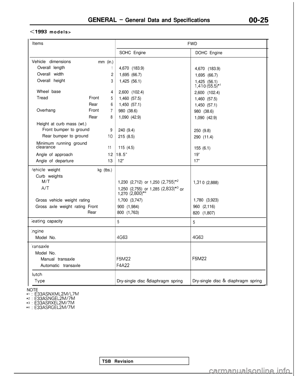
GENERAL - General Data and Specifications00-25
(1993 models
>
Items
FWD
SOHC Engine DOHC Engine
Vehicle dimensionsmm (in.)
Overall length14,670 (183.9)
4,670 (183.9)
Overall width21,695 (66.7)1,695 (66.7)
Overall height31,425 (56.1)1,425 (56.1) I,41
0
(55.5)*’
Wheel base4
2,600 (102.4)
2,600 (102.4)
Tread Front51,460 (57.5)1,460 (57.5)
Rear
61,450 (57.1) 1,450 (57.1)
Overhang Front7980 (38.6)980 (38.6)
Rear
81,090 (42.9) 1,090 (42.9)
Height at curb mass (wt.)
Front bumper to ground
9240 (9.4) 250 (9.8)
Rear bumper to ground10215 (8.5)290 (11.4)
Minimum running ground
clearance11115 (4.5)155 (6.1)
Angle of approach 12 18.5”19”
Angle of departure13 12”17”
lehicle weightkg (tbs.)
Curb weights
M/T
1,230 (2,712) or1,250 (2,755)*’I,31
0 (2,888)
A/T1,250 (2,755) or1,285(2,833)*3or1,270 (2,800)*4
Gross vehicle weight rating1,700 (3,747) 1,780 (3,923)
Gross axle weight rating Front900 (1,984)960 (2,116)
Rear 800 (1,763)
820 (1,807)
ieating capacity55lngine
Model No.
4G634G63 -ransaxle
Model No. Manual transaxle
F5M22 F5M22
Automatic transaxle
F4A22 lutch
Type
Dry-single disc & diaphragm spring
Dry-single disc &
diaphragm spring
d
TSB Revision
NOTE*l : E33ASNXML2MlL7M*2 : E33ASNGEL2MI7M*3 :
E33ASRXEL2M/7M*4 :
E33ASRGEL2M/7M
Page 116 of 1273
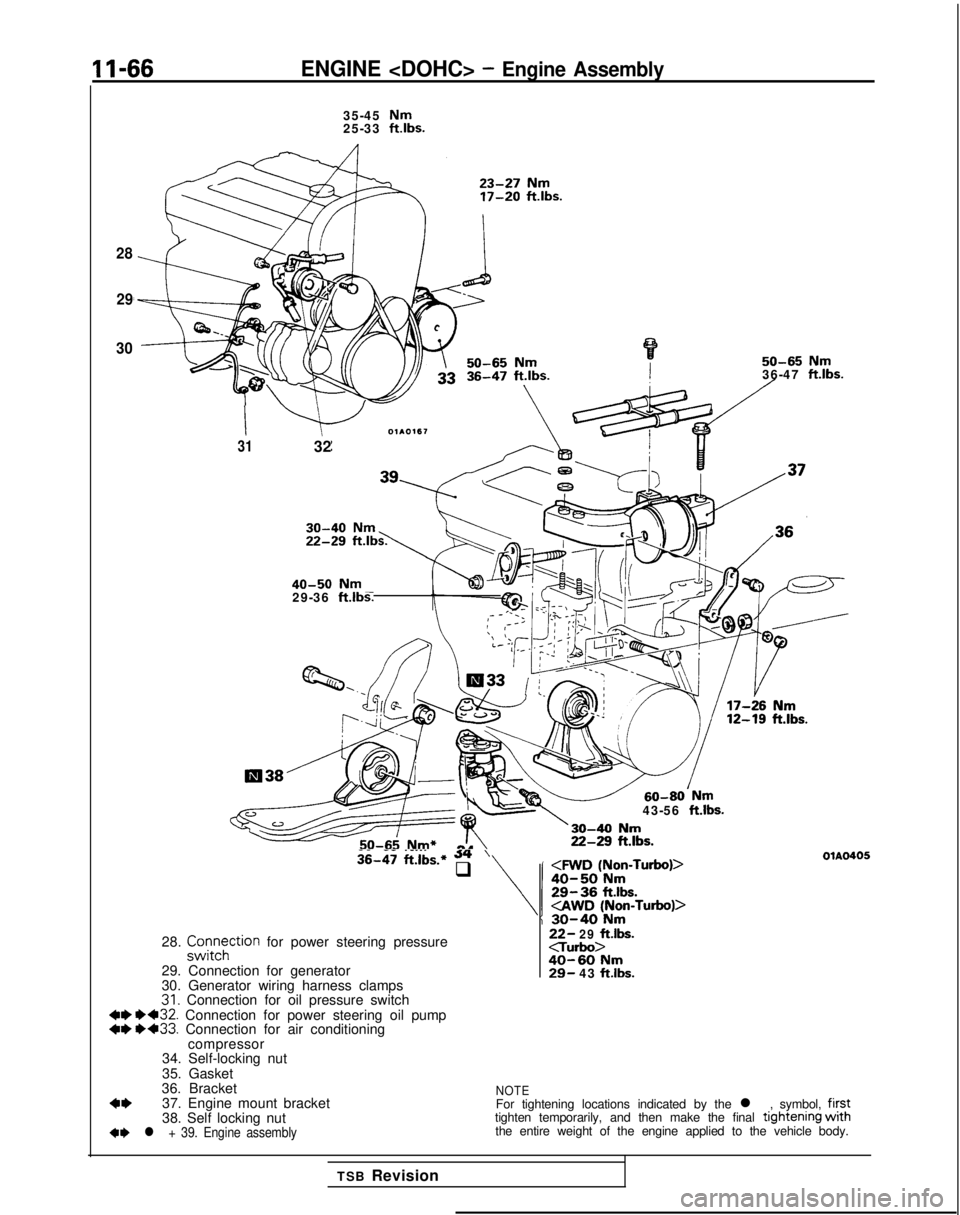
11-66ENGINE
28
29
30
35-45 Nm25-33 ftlbs.
50-65 Nm36-47 ft.lbs.
I
3132
40-50
Nm29-36 ftlbs.
43-56
ft.lbs.
-- .__.. 36-47
ft.lbs.* 54’q
28. z;tFhction for power steering pressure
29. Connection for generator
30. Generator wiring harness clamps
31. Connection for oil pressure switch 4W 1)432.
Connection for power steering oil pump
++ ++33. Connection for air conditioning
compressor
34. Self-locking nut
35. Gasket
36. Bracket
4*37. Engine mount bracket
38. Self locking nut
+e l + 39. Engine assembly
22- 29 ftlbs.c-rurbo>40-60 Nm29- 43 ftlbs.
OlAO405
NOTEFor tightening locations indicated by the l , symbol, firsttighten temporarily, and then make the final tlghtenlng withthe entire weight of the engine applied to the vehicle body.
TSB Revision
Page 674 of 1273
22-10MANUAL TRANSAXLE
e
TRANSAXLE
REMOVAL AND INSTALLATION
MZMA-A
27-34 Nm20-25 ft.lbs.
60-80
Nm*
43-58 ft.lbs.*
11-16
ft.lbs.71
11-16 ftlbs.
Removal steps
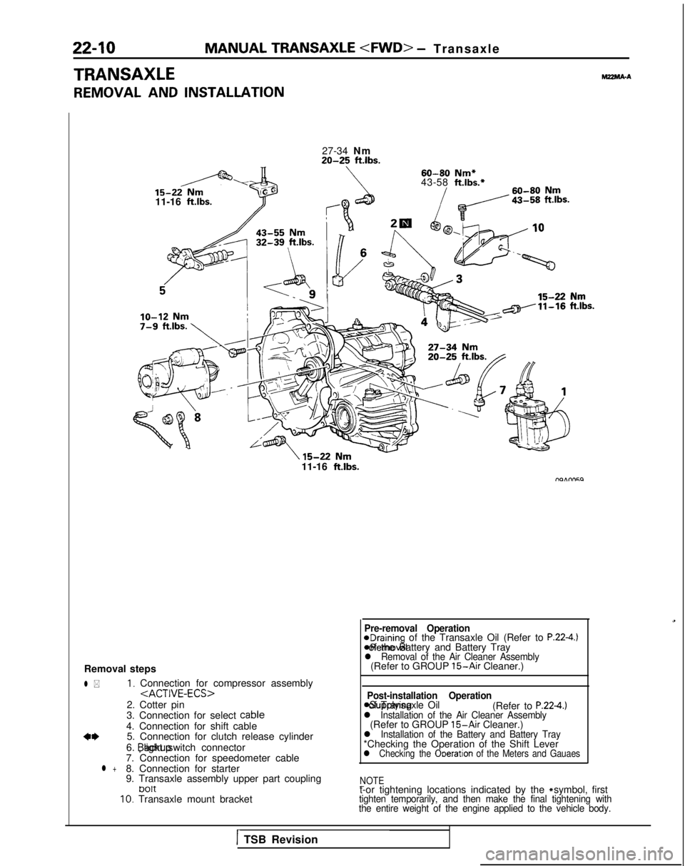
l *1, Connection for compressor assembly
2. Cotter pin
3. Connection for select cable
4. Connection for shift cable
a*5. Connection for clutch release cylinder
6. backup light switch connector
7. Connection for speedometer cable
l +8. Connection for starter
9. Transaxle assembly upper part coupling
tJ01t10. Transaxle mount bracket
Pre-removal Operation@Draining of the Transaxle Oil (Refer to P.22-4.) *Removal of the Battery and Battery Tray
l Removal of the Air Cleaner Assembly(Refer to GROUP 15-Air Cleaner.)
Post-installation Operation
asupplying of Transaxle Oil
(Refer to P.224.)l Installation of the Air Cleaner Assembly(Refer to GROUP 15-Air Cleaner.)l Installation of the Battery and Battery Tray*Checking the Operation of the Shift Leverl Checking the Ooeration of the Meters and Gauaes
NOTE
-t-or tightening locations indicated by the * symbol, firsttighten temporarily, and then make the final tightening with
the entire weight of the engine applied to the vehicle body.
1TSB Revision
Page 684 of 1273
22-20MANUAL TRANSAXLE
TRANSAXLE
REMOVAL AND INSTALLATIONMZMA-B
l Removal of the Battery and Battery Tray*Removal of the Air Cleaner Assembly
(Refer to GROUP 15-Air Cleaner.)
15-22
Nm11-16 ft.lbs.-
lo-12 Nm7-8 ft.lbs.;
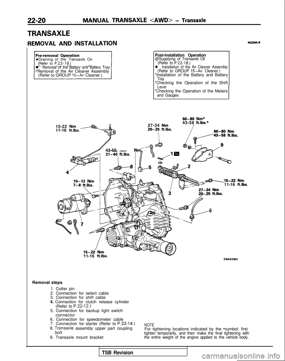
Post-installation Operation@Supplying of Transaxle Oil (Refer to P.22-18.)l Installation of the Air Cleaner Assembly(Refer to GROUP 15-Air Cleaner.)*Installation of the Battery and BatteryTray*Checking the Operation of the ShiftLever*Checking the Operation of the Metersand Gauges
60-80
Nm*
27-34
Nm43-58ft.lbs.*
20-25ft.lbs.60-80Nm
43-55 Nm _
15-22’ Nm11-16 ft.lbs.
6
-15-22 Nm11-16 ftlbs.
09AOOS4
Removal steps
1. Cotter pin
2. Connection for select cable
3. Connection for shift cable
4. Connection for clutch release cylinder (Refer to
P.22-12.)5. Connection for backup light switchconnector
6. Connection for speedometer cable
7. Connection for starter (Refer to
P.22-14.)8. ;,,:saxle assembly upper part coupling
9. Transaxle mount bracketNOTEFor tightening locations indicated by the * symbol. firsttighten temporarily, and then make the final tightening with
the entire weight of the engine applied to the vehicle body.
TSB Revision
Page 844 of 1273
26-14
FRONT AXLE - Drive Shaft
Pfb
1
+$$$A
y 7
@j
Qp I
\“dt 5
\
.i 1J Jd
llRO(O1 llE526
i+gJ#
\
‘II 1m\IIIJ I+
1
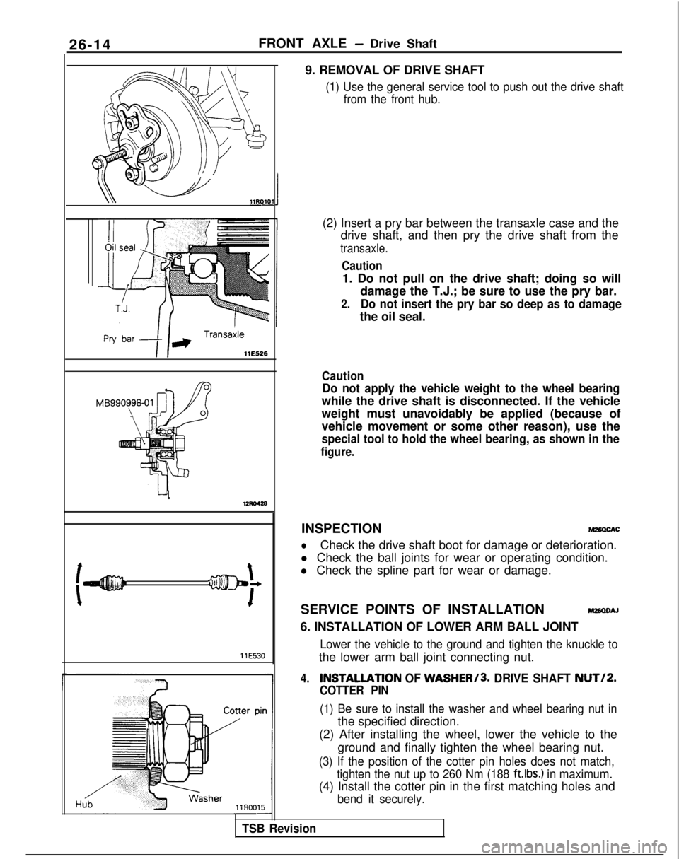
llE5309. REMOVAL OF DRIVE SHAFT
(1) Use the general service tool to push out the drive shaft
from the front hub.
(2) Insert a pry bar between the transaxle case and thedrive shaft, and then pry the drive shaft from the
transaxle.
Caution
1. Do not pull on the drive shaft; doing so will
damage the T.J.; be sure to use the pry bar.
2.Do not insert the pry bar so deep as to damage
the oil seal.
Caution
Do not apply the vehicle weight to the wheel bearing
while the drive shaft is disconnected. If the vehicle
weight must unavoidably be applied (because of
vehicle movement or some other reason), use the
special tool to hold the wheel bearing, as shown in the
figure.
4.INSTALlATlON OF WASHER/3. DRIVE SHAFT NUT/P.
COTTER PIN
(1) Be sure to install the washer and wheel bearing nut in
the specified direction.
(2) After installing the wheel, lower the vehicle to the
ground and finally tighten the wheel bearing nut.
(3) If the position of the cotter pin holes does not match, tighten the nut up to 260 Nm (188
ft.lbs.) in maximum.
(4) Install the cotter pin in the first matching holes and
bend it securely.
TSB Revision
INSPECTIONM28OChC
lCheck the drive shaft boot for damage or deterioration.
l Check the ball joints for wear or operating condition.
l Check the spline part for wear or damage.
SERVICE POINTS OF INSTALLATION
w26QDAJ
6. INSTALLATION OF LOWER ARM BALL JOINT
Lower the vehicle to the ground and tighten the knuckle to
the lower arm ball joint connecting nut.