1989 MITSUBISHI GALANT oil change
[x] Cancel search: oil changePage 40 of 1273
00-38GENERAL- Scheduled Maintenance Table
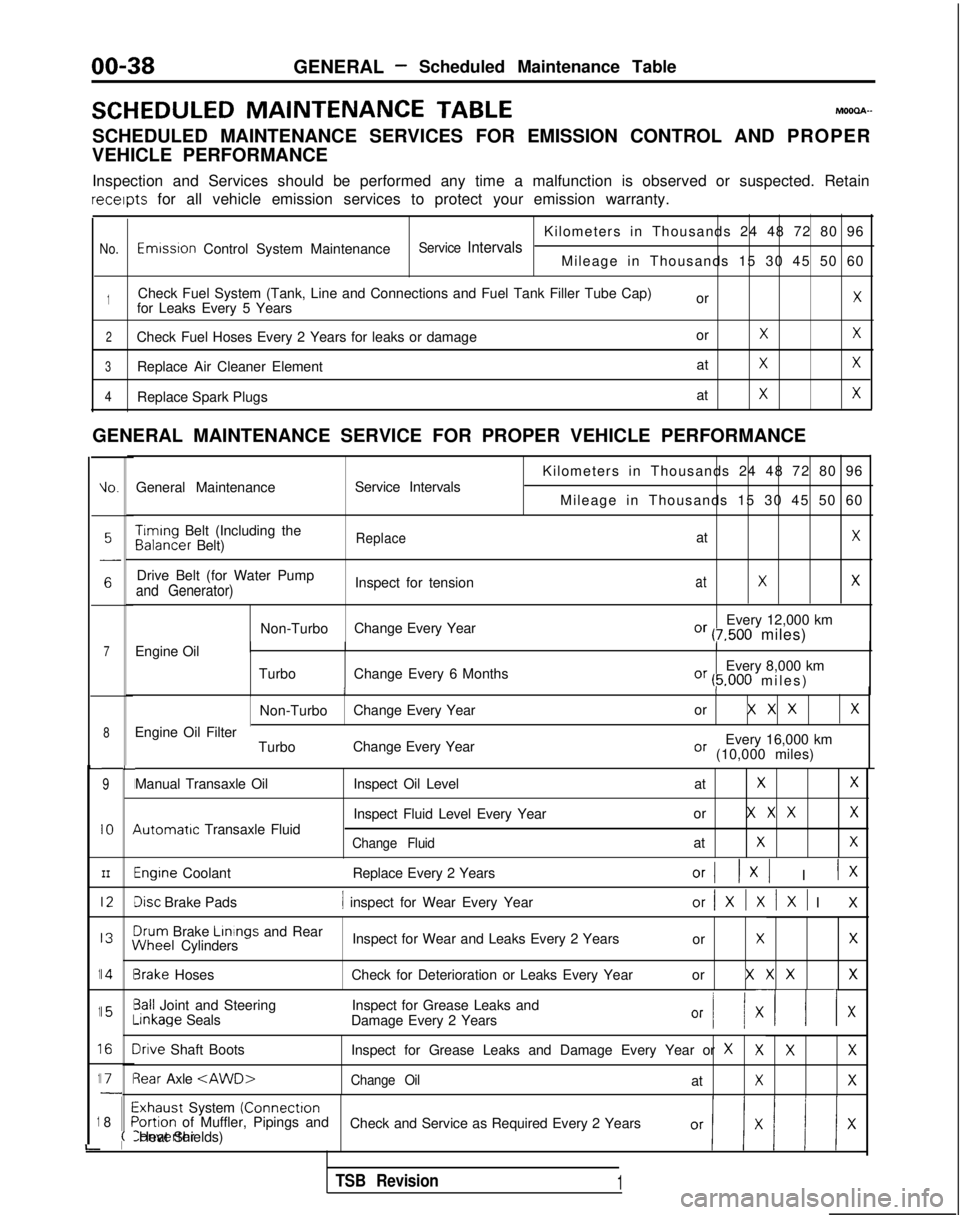
SCHEDULED MAINTENANCE
TABLEMOOOA-
SCHEDULED MAINTENANCE SERVICES FOR EMISSION CONTROL AND PROPER
VEHICLE PERFORMANCE
Inspection and Services should be performed any time a malfunction is ob\
served or suspected. Retain receipts
for all vehicle emission services to protect your emission warranty.
Kilometers in Thousands 24 48 72 80 96
No.Emwsron Control System MaintenanceService IntervalsMileage in Thousands 15 30 45 50 60
1Check Fuel System (Tank, Line and Connections and Fuel Tank Filler Tube\
Cap) orXfor Leaks Every 5 Years
2Check Fuel Hoses Every 2 Years for leaks or damage orXX
3Replace Air Cleaner ElementatXX
4Replace Spark PlugsatXX
GENERAL MAINTENANCE SERVICE FOR PROPER VEHICLE PERFORMANCE
L
1
1
1
1
1
i
IO.General Maintenance
Service Intervals
7Engine Oil
8
9
IO
III2
I3
14
15
I6
I71
8
L
I
I
I
I
I\
I
II
I
I
;(
Kilometers in Thousands 24 48 72 80 96
Mileage in Thousands 15 30 45 50 60 Timing
Belt (Including the Balancer
Belt)
ReplaceatX
Drive Belt (for Water Pump
Inspect for tensionatXXand Generator)
Non-TurboChange Every Year Every 12,000 kmOr (7,500 miles)
Turbo Change Every 6 Months Every 8,000 km
Or (5.000 miles
)
II
Non-Turbo
Change Every Year or X X XX
Every 16,000 kmOr (10,000 miles)
Engine Oil Filter
TurboChange Every Year
Manual Transaxle Oil 4utomatrc
Transaxle Fluid Inspect Oil Level
at
XX
Inspect Fluid Level Every Yearor X X XX
Change FluidatXX
Engine Coolant
Replace Every 2 YearsOrI 1x1 I IX
Disc Brake Pads1 inspect for Wear Every Yearor/XlXlXl I
X
3rum
Brake Linings
and Rear iNheel
Cylinders Inspect for Wear and Leaks Every 2 Years
or
XX
3rake HosesCheck for Deterioration or Leaks Every Year or X X XX
3all Joint and SteeringInspect for Grease Leaks and-inkage
Seals
Damage Every 2 Years
Or I/ XII x
Irive Shaft Boots Inspect for Grease Leaks and Damage Every Year or XXXX
3ear Axle
Exhaust System (Connectron>ortion of Muffler, Pipings and
Check and Service as Required Every 2 YearsConverter Heat Shields)
TSB Revision1
Page 41 of 1273
GENERAL - Scheduled Maintenance Table/Maintenance Service00-39
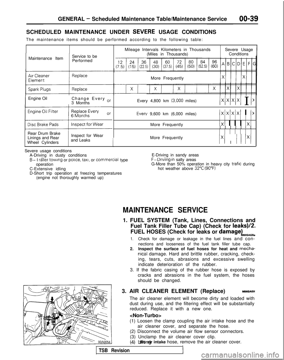
SCHEDULED MAINTENANCE UNDER SEVEiRE USAGE CONDITIONS
The maintenance items should be performed according to the following tab\
le:
Maintenance Item Service to be
Performed
IEngine Oil Change Every or
3 Months
(:z:.:a::I
Rear Drum Brake
Linings and Rear
Wheel Cylinders Inspect for Wear
and Leaks
1
Mileage Intervals Kilometers in Thousands (Miles in Thousands) Severe Usage
Conditions
More Frequently
Every 4,800 km
(3,000 miles)/xlxlx/xI I I1 Every
9,600 km (6,000 miles)
IxIxlxIxI I I>(
More Frequently1x1 I I I 1x1I I I I I I I
More Frequently
Ix1 I I I lx/
Severe usage conditions A-Driving in dusty conditions
- -B- I railer
towing or police.
taxi,
or commercial
type
operation
C-Extensive idling
D-Short trip operation at freezing temperatures (engine not thoroughly warmed up) E-Driving in sandy areas- -..F-Dnvlng In salty areas
G-More than 50% operation in heavy city trafic during
hot weather above 32°C (90°F)
MAINTENANCE SERVICE
1. FUEL SYSTEM (Tank, Lines, Connections and
Fuel Tank Filler Tube Cap) (Check for leaks)/2.
FUEL HOSES (Check for leaks or
damagekOOSnOB.
1.Check for damage or leakage in the fuel lines and con-
nections and looseness of the fuel tank filler tube cap.
2. Inspect the surface of fuel hoses for heat and mecha-
nicall damage. Hard and brittle rubber, cracking, check-
ing, tears, cuts, abrasions and excessive swelling
indicate deterioration of the rubber.
3. If the fabric casing of the rubber hose is exposed by cracks and abrasions in the fuel system, the hoses
should be changed.
3. AIR CLEANER ELEMENT (Replace)
MMlSAKH
The air cleaner element will become dirty and loaded with dust during use, and the filtering effect will be substantiallyreduced. Replace it with a new one.
(1) Loosen the clamp coupling the air intake hose and the air cleaner cover, and separate the hose.
(2) Disconnect the volume air flow sensor connectors.
(3) Unclamp the air cleaner cover clip.
(4) Lifting the air intake hose, remove the air cleaner cover.
TSB Revision1
Page 43 of 1273
GENERAL - Maintenance Service00-41
-1
6COOO9
L!6COO39
OlR0344
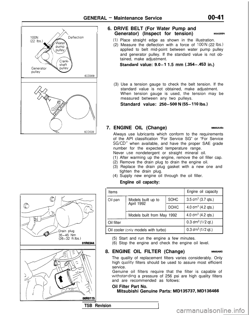
6. DRIVE BELT (For Water Pump and
Generator) (Inspect for tension)
MOOSBBN
(1) Place straight edge as shown in the illustration.
(2) Measure the deflection with a force of
100 N (22 Ibs.)
applied to belt mid-point between water pump pulley
and generator pulley. If the standard value is not ob-
tained, make adjustment.
Standard value: 9.0-l 1.5 mm (.354-.453
in.)
(3) Use a tension gauge to check the belt tension. If the standard value is not obtained, make adjustment.
When tension gauge is used, the tension may be
measured between any two pulleys.
Standard value:
250-500 N (55-110
Ibs.)
7. ENGINE OIL (Change)MOOSAABc
Always use lubricants which conform to the requirements
of the API classification “For Service SG” or “For Service SG/CD”
when available, and have the proper SAE grade
number for the expected temperature range.
Never
Lose nondetergent or straight mineral oil.
(1) After warming up the engine, remove the oil filler cap.
(2) Remove the drain plug to drain the engine oil. (3) Replace the drain plug gasket with a new one and
tighten the drain plug.
(4) Supply new engine oil through the oil filler.
Engiine oil capacity:
Items Engine oil capacity
Oil pan
1
Models built up toSOHC3.5 dm3 (3.7 qts.)
April 1992DOHC4.0 dm3 (4.2 qts.)
Models built from May 19924.0 dm3 (4.2 qts.)
Oil filter 0.3 dm3 (l/2 qt.)
Oil cooler
(clnly models with turbo) 0.3 dm3 (I/2 qt.)
(5) Start and run the engine a few minutes.
(6) Stop the engine and check the engine oil level.
8. ENGINE OIL FILTER (Change)
MOOSABG
The quality of replacement filters varies considerably. Only high
quatlity filters should be used to assure most efficient
service. Genuine oil filters require that the filter is capable of
withstarlding a pressure of 256 psi are high quality filters
and are recommended as follows:
Oil Filter Part No.
Mitsubishi Genuine Parts: MD135737,
MD136466
TSB Revision
Page 46 of 1273
GENERAL -Maintenance Service
(1O)Star-t engine and allow to idle for at least two minutes.
Then, with parking brake on, move selector
fever
momentarily to each position, ending in “N” Neutral
position.
(11)Add sufficient ATF to bring fluid level to lower mark.
Recheck fluid level after transaxle is at normal Operating
temperature. Fluid level should be between upper and lower marks of
“HOT” range, Insert dipstick fully to prevent dirt from
entering transaxle.
OOA0051
11 .ENGINE
COOLANT (Change)MOOSEEAC
Check the cooling system parts, such as radiator, heater,
and oil cooler hoses, thermostat and connections for
leakage and damage.
CHANGE COOLANT
1. Remove the radiator cap.
2. Loosen the drain plug to drain the coolant.
3. Drain the coolant from the reserve tank.
4. After draining the coolant, tighten the drain plug securely.
5.Supply the coolant into the radiator until it is filled up to
its filler neck.
6. Supply the coolant into the reserve tank.
7. After warming the engine until the thermostat opens, remove the radiator cap and check the coolant level.
8.Supply the coolant into the radiator until it is filled up to
its filler neck, and install the radiator cap securely.
9.Fill the reserve tank with coolant up to the “FULL” line.
14K512
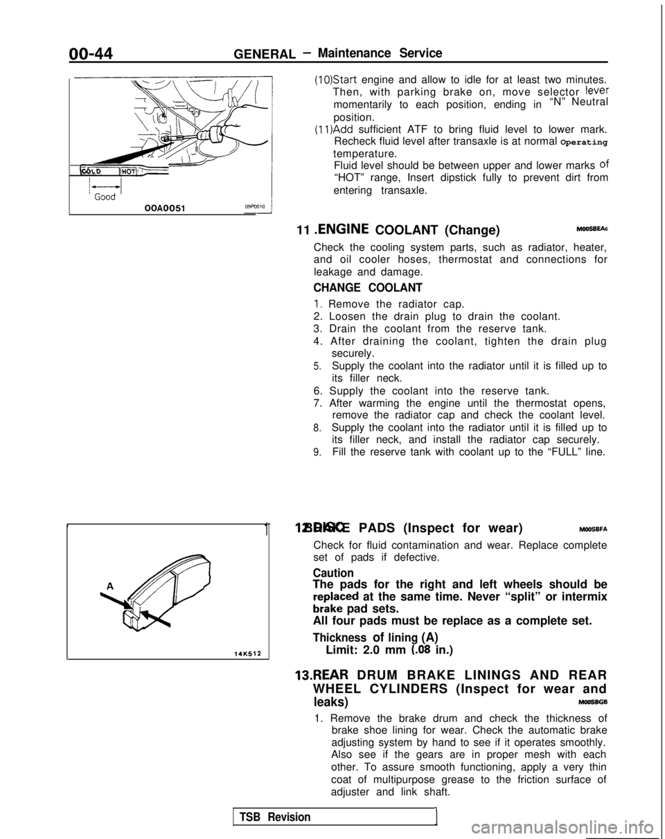
1 12.DISC BRAKE PADS (Inspect for wear) MWSBFA
Check for fluid contamination and wear. Replace complete
set of pads if defective.
Caution
The pads for the right and left wheels should be
reDlaced at the same time. Never “split” or intermix
brkke pad sets.
All four pads must be replace as a complete set.
Thickness of lining (A)
Limit: 2.0 mm (.08 in.)
13.REAR DRUM BRAKE LININGS AND REAR
WHEEL CYLINDERS (Inspect for wear and
leaks)MOOSBGB
1. Remove the brake drum and check the thickness of brake shoe lining for wear. Check the automatic brake
adjusting system by hand to see if it operates smoothly.
Also see if the gears are in proper mesh with each
other. To assure smooth functioning, apply a very thin
coat of multipurpose grease to the friction surface of
adjuster and link shaft.
TSB Revision1
Page 56 of 1273
11-6
ToolENGINE
-Special Tools/Troubleshooting
Number
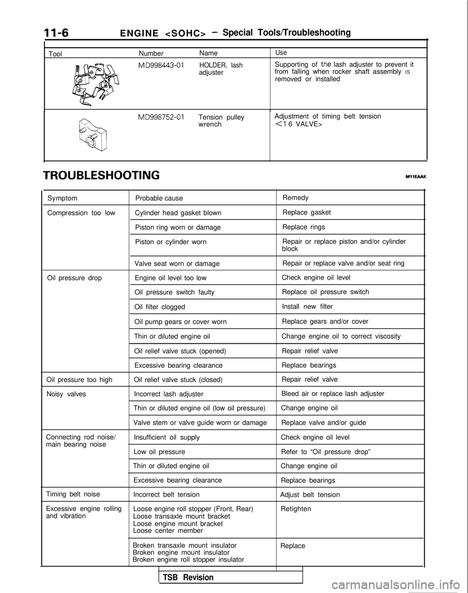
NameUse
M
D998443-01 HOLDER, lashSupporting of the lash adjuster to prevent it
adjuster from falling when rocker shaft assembly
IS
removed or installed MD998752-01
Tension pulley Adjustment of timing belt tension
wrench
TROUBLESHOOTINGMHEAAK
Symptom
Compression too low Probable cause
Cylinder head gasket blown Piston ring worn or damage
Piston or cylinder worn Remedy
Replace gasket
Replace rings
Repair or replace piston and/or cylinder
block
Valve seat worn or damage Repair or replace valve and/or seat ring
Oil pressure drop Engine oil level too low Check engine oil level
Oil pressure switch faulty Replace oil pressure switch
Oil filter clogged Install new filter
Oil pump gears or cover worn Replace gears and/or cover
Thin or diluted engine oil Change engine oil to correct viscosity
Oil relief valve stuck (opened) Repair relief valve
Excessive bearing clearance Replace bearings
Oil pressure too high Oil relief valve stuck (closed) Repair relief valve
Noisy valves Incorrect lash adjuster Bleed air or replace lash adjuster
Thin or diluted engine oil (low oil pressure) Change engine oil
Valve stem or valve guide worn or damage Replace valve and/or guide
Connecting rod noise/ Insufficient oil supply Check engine oil level
main bearing noise
Low oil pressure Refer to “Oil pressure drop”
Thin or diluted engine oil Change engine oil
Excessive bearing clearance Replace bearings
Timing belt noise Incorrect belt tension Adjust belt tension
Excessive engine rolling Loose engine roll stopper (Front, Rear)
and vibration Retighten
Loose transaxle mount bracket
Loose engine mount bracket
Loose center member
Broken transaxle mount insulator
Broken engine mount insulator
Broken engine roll stopper insulator Replace
TSB Revision
Page 88 of 1273
11-38
ENGINE
Rubber
exposed
Tooth missing
and
canvas fiber exposed
lEN0002
Crankshaft
sprocket “B”
Crankshaft
aENzo4
Spacer
Chamfered
6EN009
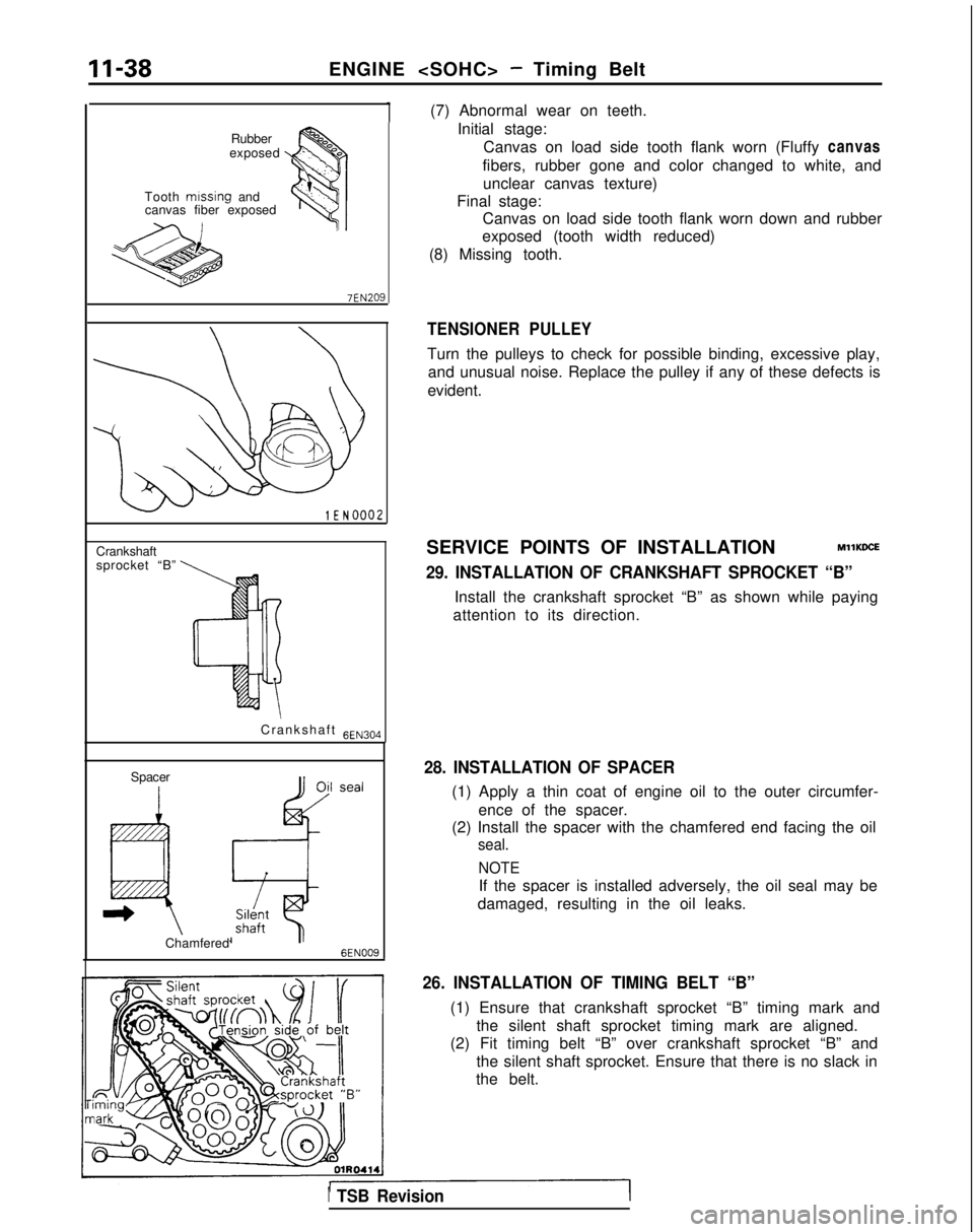
(7) Abnormal wear on teeth.Initial stage:Canvas on load side tooth flank worn (Fluffy canvas
fibers, rubber gone and color changed to white, and unclear canvas texture)
Final stage: Canvas on load side tooth flank worn down and rubber
exposed (tooth width reduced)
(8) Missing tooth.
TENSIONER PULLEY
Turn the pulleys to check for possible binding, excessive play, and unusual noise. Replace the pulley if any of these defects is
evident.
SERVICE POINTS OF INSTALLATION
MllKDCE
29. INSTALLATION OF CRANKSHAFT SPROCKET “B”
Install the crankshaft sprocket “B” as shown while paying
attention to its direction.
28. INSTALLATION OF SPACER
(1) Apply a thin coat of engine oil to the outer circumfer-
ence of the spacer.
(2) Install the spacer with the chamfered end facing the oil
seal.
NOTE
If the spacer is installed adversely, the oil seal may be
damaged, resulting in the oil leaks.
26. INSTALLATION OF TIMING BELT “B”
(1) Ensure that crankshaft sprocket “B” timing mark and the silent shaft sprocket timing mark are aligned.
(2) Fit timing belt “B” over crankshaft sprocket “B” and
the silent shaft sprocket. Ensure that there is no slack in
the belt.
1 TSB Revision
Page 224 of 1273
13-82 FUEL SYSTEM
OPERATION
l The power-steering pressure switch functions
to convert data as to whether there is or is not apower steering load to LOW-or HIGH-level vol-
tage, and the resulting signals are input to the engine control module. The engine control mod-
ule, based upon those signals, regulates the
idle-speed control motor. l The battery voltage within the engine control
module is applied, by way of the resistance, to
the power-steering pressure switch. When
steering maneuvers are made, the pressure of
the power-steering oil increases, thus switching
ON the power-steering pressure switch, with
the result that the current is grounded. As a re-
sult, the power-steering pressure switch vol-
tage changes from HIGH level to LOW level.
INSPECTION I) Using Scan tool
Function
Item No.
Data reading 27
Data displayInspection conditions Steering wheelNormal indication
Switch status Engine: IdlingSteering wheel idle stateOFF
During steering wheelONoperation
(2) Checking Oil Pressure
Steering wheel
Straight forward
Turned
Oil pump delivery pressure (ref. value)
less than 1,470- 1,961 kPa (213-284 psi)
more than
1,470- 1,961 kPa (213-284 psi)
HARNESS INSPECTION
I-E-I
Harness side connector 6 0
@=- -0
Q
4 1
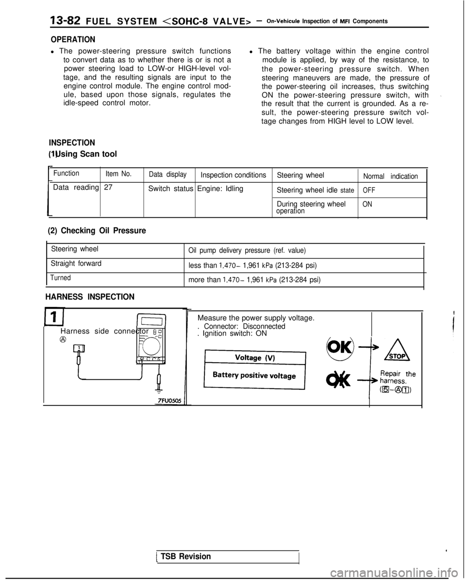
Measure the power supply voltage.
. Connector: Disconnected. Ignition switch: ON
[ TSB Revision
Page 232 of 1273
13-90 FUEL SYSTEM
INJECTORS
Fuel
Connector
Solenoid coil
Plunger
Needle valve -----I
InjectionFilter6FUO514
M13rrAA
Multiport
fuel injection relay
No.1 &j No.2& No.3& No,4+
tI
lFUO642
Engine control module connector
CJ=JW=U-I
0 1 LO636
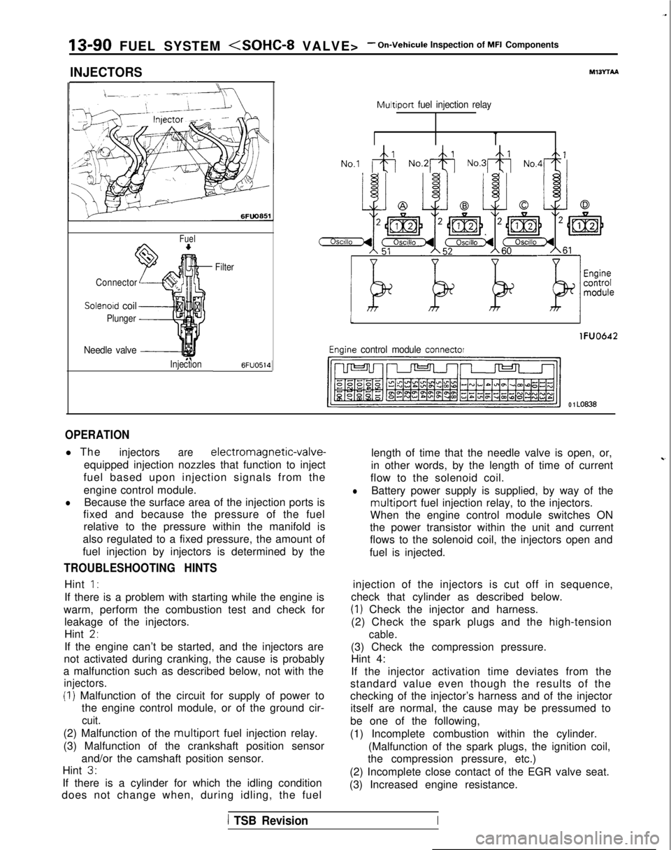
OPERATION
l The
injectorsare electromagnetic-valve-
equipped injection nozzles that function to inject
fuel based upon injection signals from the
engine control module.
lBecause the surface area of the injection ports is
fixed and because the pressure of the fuel
relative to the pressure within the manifold is
also regulated to a fixed pressure, the amount of
fuel injection by injectors is determined by the
TROUBLESHOOTING HINTS
Hint 1:
If there is a problem with starting while the engine is
warm, perform the combustion test and check for leakage of the injectors.
Hint
2,
If the engine can’t be started, and the injectors are
not activated during cranking, the cause is probably
a malfunction such as described below, not with the
injectors.
(I) Malfunction of the circuit for supply of power to the engine control module, or of the ground cir-
cuit.
(2) Malfunction of the multiport fuel injection relay.
(3) Malfunction of the crankshaft position sensor and/or the camshaft position sensor.
Hint
3.
If there is a cylinder for which the idling condition
does not change when, during idling, the fuel length of time that the needle valve is open, or,
in other words, by the length of time of current
~-
flow to the solenoid coil.
lBattery power supply is supplied, by way of the
multiport fuel injection relay, to the injectors.
When the engine control module switches ON
the power transistor within the unit and current
flows to the solenoid coil, the injectors open and
fuel is injected.
injection of the injectors is cut off in sequence,
check that cylinder as described below.
(1) Check the injector and harness.
(2) Check the spark plugs and the high-tension
cable.
(3) Check the compression pressure. Hint 4:
If the injector activation time deviates from the
standard value even though the results of the
checking of the injector’s harness and of the injector itself are normal, the cause may be pressumed to
be one of the following,
(1) Incomplete combustion within the cylinder. (Malfunction of the spark plugs, the ignition coil,
the compression pressure, etc.)
(2) Incomplete close contact of the EGR valve seat.
(3) Increased engine resistance.
1 TSB RevisionI