Page 367 of 1273
FUEL SYSTEM - Troubleshooting
gSY’
I,
I
I------
@J
F
&-------
IOPIGl,
2-BW
7 C-08
c-39
B-22-
m
j:
z
d
IO-------
-
TSB Revision
I
1IGNITION
POWER
TRANSISTOR z+
I 7
P
54-------
CONDENSER(4WD),Icl 2
g
4x6,<8d\lI\
GNITION COIL
B-07
I
bh!ZPARK
B-09 _*v13.4 5 8 I II
>
109I53
COMBINATIONMETER
C-52
L
A
t h
55----------------~-~--~------------.
!7
I
3
J/B
1 7
8
>
1
33
x
Page 372 of 1273
13-230FUEL SYSTEM - Troubleshooting
CIRCUIT DIAGRAM (CONTINUED)
< 1992 models (Non-turbo)>
8 i8
2
r:
2
c:_---s-w
!
o---”
2
Es_------
ON(IGl)
2-BW
C-08
B-22-
I.@
CONDENSERz(4WD)ci
j:
zd
XL-----
I
9I I:
IGNITION COIL
B-07:
$1 I@- 41 IF$2El3
352'"1m9
TSB Revision
IGNITION"7POWER-/?li~SISTOR +5
I e 3 4 5.8 7 e
ENGINE 6PEED>L"2;; DETECTION3 CONNECTOR
In
109
Fe
c-09
F;;
A
f ii
~~-_____-------------------------------
8-
>
1
13
7
1
J/B
7
Page 465 of 1273
FUEL SYSTEM - Fuel Tank 4WD>13-323
03AOllO03AOlll
f%? hose
‘F;el high pressure
-Fuelgaugeand \n pump assembly- 03AO107
TSB Revision
FUEL PUMP AND GAUGE ASSEMBLY REPLACE-
MENT
MlBGEAG
(1) Remove the protectors.
(2) Disconnect the fuel pump and gauge assembly harness connector, and then remove the hole cover.
(3) Bleed the remaining pressure from the fuel pipe line to prevent fuel discharge. (Refer to
P.13-312.)
(4) Disconnect fuel high pressure hose and remove the fuel
tank pressure control valve, then remove the fuel pumpand gauge assembly.
(5) Apply the specified sealant to the rear floor pan.
Specified sealant: 3M ATD Part No.8625 or equivalent
(6) After installing the fuel pump and gauge assembly, start the
engine and check to ensure that there is no fuel leakage.
Page 795 of 1273
AUTOMATIC TRANSAXLE - Service Adjustment Procedures23-89
4WD . . . Up to 1992 model
Oilerature sensor
FWD . . . From MODEL 1990.5
5. Remove the solenoid valve connector holding clip, andpress in the connector.
6.Press the tabs of the solenoid valve harness grommet, and
then push into the case and remove.
Page 810 of 1273

23-104AUTOMATIC TRANSAXLE - Transaxle Assembly 4WD>
OPTIONAL12K513
Pry baraTransaxle
llKf311I
SERVICE POINTS OF REMOVALM23LBAK
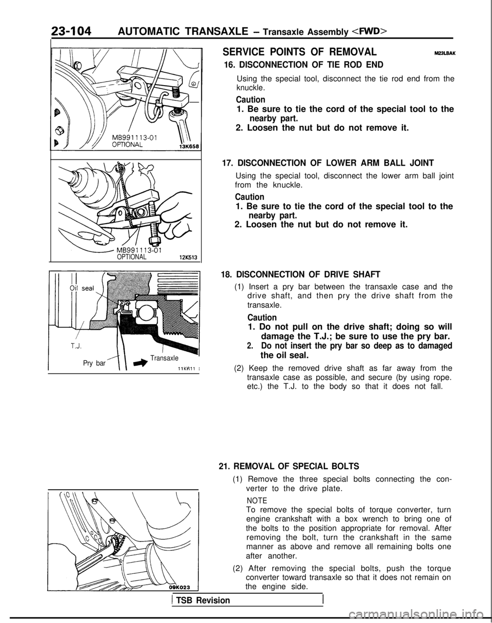
16. DISCONNECTION OF TIE ROD END
Using the special tool, disconnect the tie rod end from the
knuckle.
Caution
1. Be sure to tie the cord of the special tool to the
nearby part.
2. Loosen the nut but do not remove it.
17. DISCONNECTION OF LOWER ARM BALL JOINT
Using the special tool, disconnect the lower arm ball joint
from the knuckle.
Caution
1. Be sure to tie the cord of the special tool to the
nearby part.
2. Loosen the nut but do not remove it.
18. DISCONNECTION OF DRIVE SHAFT
(1) Insert a pry bar between the transaxle case and the drive shaft, and then pry the drive shaft from the
transaxle.
Caution
1. Do not pull on the drive shaft; doing so will
damage the T.J.; be sure to use the pry bar.
2.Do not insert the pry bar so deep as to damaged
the oil seal.
(2) Keep the removed drive shaft as far away from the transaxle case as possible, and secure (by using rope.
etc.) the T.J. to the body so that it does not fall.
21. REMOVAL OF SPECIAL BOLTS
(1) Remove the three special bolts connecting the con-
verter to the drive plate.
NOTE
To remove the special bolts of torque converter, turnengine crankshaft with a box wrench to bring one of
the bolts to the position appropriate for removal. After removing the bolt, turn the crankshaft in the same
manner as above and remove all remaining bolts one
after another.
(2) After removing the special bolts, push the torque converter toward transaxle so that it does not remain on
the engine side.
1 TSB Revision
Page 868 of 1273
27-8REAR AXLE -4WD>- Rear Axle Hub
REAR AXLE HUB
REMOVAL AND INSTALLATION
M27MA-A
9-14 Nm7-10 ft.lbs.
50-60 Nm
36-43 ftlbs.
Removal steps
+*1. Rear speed sensor 4*2. Caliper assembly
3. Brake disc
I!jiEl 4
llA0030
4. Hub capl 45.
Nut6.Tonguedwasher
7. Rear hub assembly+*8. Rear rotor 9. Rear hub bearing unit
Rear speedsensor14ROlMI
SERVICE POINTS OF REMOVAL
1. REMOVAL OF REAR SPEED SENSOR
Caution
M27wBAB
When removing the speed sensor from the adapter, be
careful that the end pole piece does not strike the teeth
of the rotor or other parts.
TSB Revision
Page 1179 of 1273

35-58SERVICE BRAKES - Service Adjustment Procedures
14*ooat
Delay
valve Bleeder screw
(for the left rear brakes)i
Bleeder screw
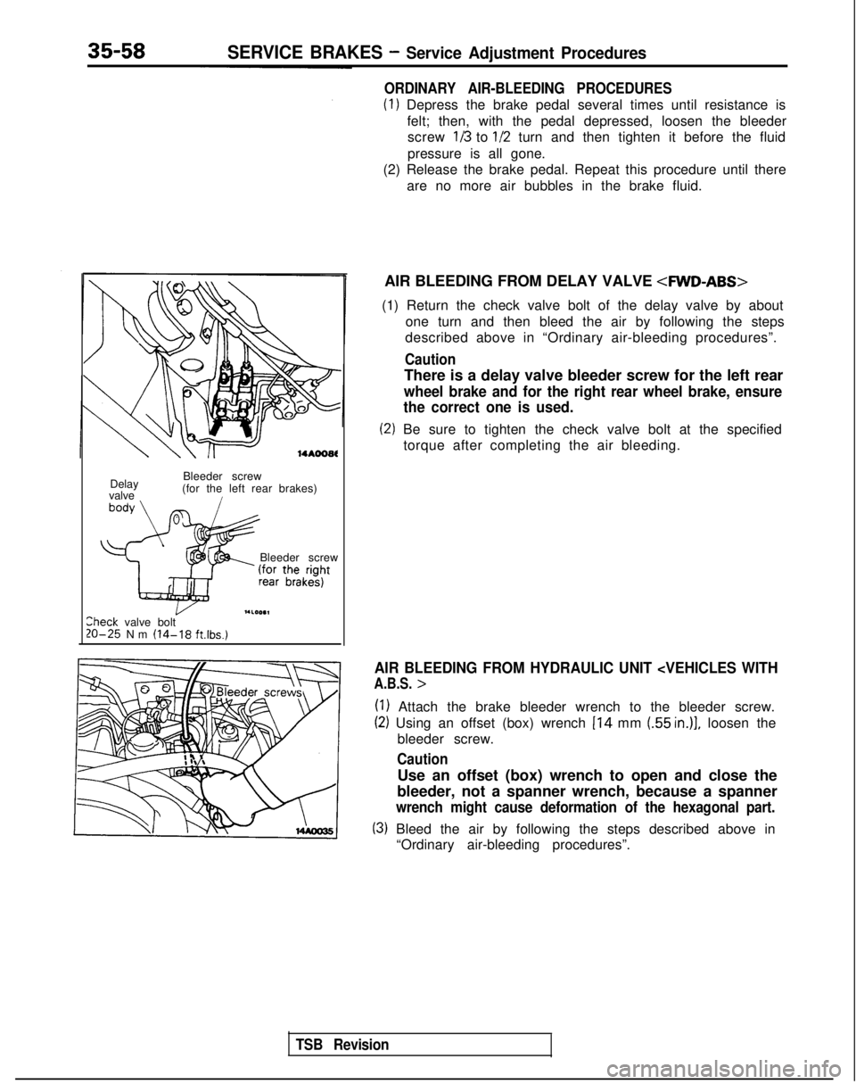
I.LOO.1lheck valve bolt20-25 Nm (14-18 ft.lbs.)
ORDINARY AIR-BLEEDING PROCEDURES
(1) Depress the brake pedal several times until resistance is
felt; then, with the pedal depressed, loosen the bleederscrew
113 to l/2 turn and then tighten it before the fluid
pressure is all gone.
(2) Release the brake pedal. Repeat this procedure until there
are no more air bubbles in the brake fluid.
AIR BLEEDING FROM DELAY VALVE
4WD-ABS>
(1) Return the check valve bolt of the delay valve by about one turn and then bleed the air by following the steps
described above in “Ordinary air-bleeding procedures”.
Caution
There is a delay valve bleeder screw for the left rear
wheel brake and for the right rear wheel brake, ensure
the correct one is used.
(2) Be sure to tighten the check valve bolt at the specified
torque after completing the air bleeding.
AIR BLEEDING FROM HYDRAULIC UNIT
A.B.S. >
(1) Attach the brake bleeder wrench to the bleeder screw.
(2) Using an offset (box) wrench 114 mm (55 in.)], loosen the
bleeder screw.
Caution
Use an offset (box) wrench to open and close the
bleeder, not a spanner wrench, because a spanner
wrench might cause deformation of the hexagonal part.
(3) Bleed the air by following the steps described above in “Ordinary air-bleeding procedures”.
TSB Revision
Page 1254 of 1273
SERV,CE BRAKES _ G-Sensor-
models>35433
14AOlss
14AOlBB
(2) Slowly inclining the G-sensor in the direction of forward
vehicle travel, check that there is no conductance above a
sensor angle of 30 degrees.
(3) Slowly inclining the G-sensor in the direction of reverse
vehicle travel, check that there is no conductance above a sensor angle of 30 degrees.
BRAKE FLUID PRESSURE SWITCH 4WD-A,.B.S.: Up to 1991 models>
REMOVAL AND INSTALLATION
Pre-removal Operationl Draining of Brake Fluid
(Refer
to P.35-57.)
Removal steps
1. W
iring harness connector
2. Brake tubes connection
3. Brake fluid pressure switch TSB
Revision I