1989 MITSUBISHI GALANT diagram
[x] Cancel search: diagramPage 3 of 1273
00-l
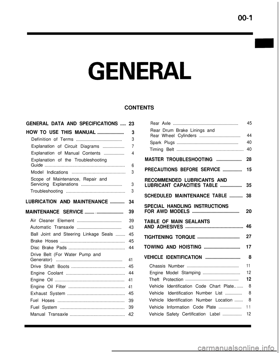
GENERAL
CONTENTS
GENERAL DATA AND SPECIFICATIONS.....23
HOWTOUSETHISMANUAL......................
3
Definition of Terms ......................................3
ExplanationofCircuitDiagrams..................7
Explanation of
ManualContents .................4
Explanation of the Troubleshooting
Guide .............................................................
6
Model
Indications .........................................3
Scope of Maintenance, Repair and
Servicing Explanations
..................................
3
Troubleshooting .............................................3
LUBRICATIONANDMAINTENANCE............
34
MAINTENANCE SERVICE............................... 39
AirCleanerElement
.....................................39
Automatic
Transaxle
.....................................43
Ball Joint and Steering Linkage Seals ........45
Brake Hoses................................................. 45
Disc Brake Pads ........................................... 44
Drive Belt (For Water Pump and
Generator) .......................................................
41
Drive
Shaft Boots .........................................45
Engine Coolant
............................................. 44
Engine Oil .....................................................
41
Engine Oil Filter ...........................................41
Exhaust System
............................................ 45
FuelHoses
...................................................39
Fuel System
.................................................39
Manual Transaxle ..........................................42
RearAxle......................................................45
Rear Drum Brake Linings and
RearWheel Cylinders
..................................44
Spark
Plugs...................................................40
Timing Belt...................................................40
MASTER
TROUBLESHOOTING.....................28
PRECAUTIONS
BEFORESERVICE................15
RECOMMENDED LUBRICANTS AND
LUBRICANT CAPACITIESTABLE..................35
SCHEDULED
MAINTENANCETABLE ...........38
SPECIAL HANDLING INSTRUCTIONS
FOR AWD MODELS
.......................................20
TABLE OF MAIN SEALANTS
AND
ADHESIVES ............................................46
TIGHTENING TORQUE
................................... 27
TOWING
ANDHOISTING ..............................17
VEHICLE
IDENTIFICATION .............................8
Chassis Number ...........................................
11
EngineModel
Stamping
...............................12
Theft Protection ............................................12
Vehicle Identification Code Chart Plate.......
8
Vehicle Identification Number List
..............8
Vehicle Identification Number Location .......
8
Vehicle Information
CodePlate...................1 1
Vehicle SafetyCertificationLabel................12
Page 6 of 1273
00-4GENERAL - How to Use This Manual
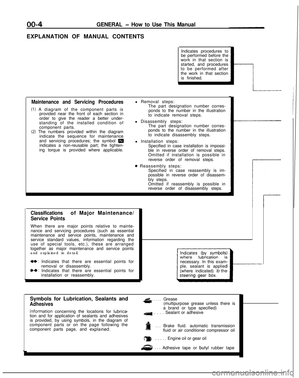
EXPLANATION OF MANUAL CONTENTSIndicates procedures to
be performed before the
work in that section is
started, and procedures
to be performed after
the work in that section
is finished.
Maintenance and Servicing Procedures
(1) A diagram of the component parts is provided near the front of each section in
order to give the reader a better under-
standing of the installed condition of
component parts.
(2) The numbers provided within the diagram indicate the sequence for maintenance
and servicing procedures; the symbol
mindicates a non-reusable part; the tighten-
ing torque is provided where applicable. l Removal steps:
The part designation number corres-
ponds to the number in the illustration
to indicate removal steps.
l Disassembly steps: The part designation number corres-
ponds to the number in the illustration
to indicate disassembly steps.
l Installation steps: Specified in case installation is impossi-
ble in reverse order of removal steps.
Omitted if installation is possible in
reverse order of removal steps.
8 Reassembly steps: Specified in case reassembly is im-
possible in reverse order of disassem-
bly steps.
Omitted if reassembly is possible in reverse order of disassembly steps.
Classificationsof Major Maintenance/
Service Points
When there are major points relative to mainte-
nance and servicing procedures (such as essential
maintenance and service points, maintenance and
service standard values, information regarding the
use of special tools, etc.), these are arranged
together as major maintenance and service points
and explained in detail.
*+ : Indicates that there are essential points for
removal or disassembly.
I)+ : Indicates that there are essential points forinstallation or reassembly. necessary. In this exam-
ple, sealant is applied
(where indicated) to the
I---
Symbols for Lubrication, Sealants and
Adhesives
4 . . . . .Grease
(multipurpose grease unless there is Information
concerning the locations for lubrica-
tion and for application of sealants and adhesives
is provided, by using symbols, in the diagram of
component parts or on the page following the
component parts page, and explarned.
a brand or type specified)
4 . . . . Sealant or adhesive
a. . . . .Brake fluid. automatic transmission
fluid or air conditioner compressor oil
a. . . . . Engine oil or gear oil
. . .Adhesive tape or butyl
rubber tape
Page 7 of 1273
GENERAL - How to Use This Manual
QfitIIICQ CTEEQINC CFAR RnY..^-TV..&” Y.LLI.II.Y Y_.. w-1.
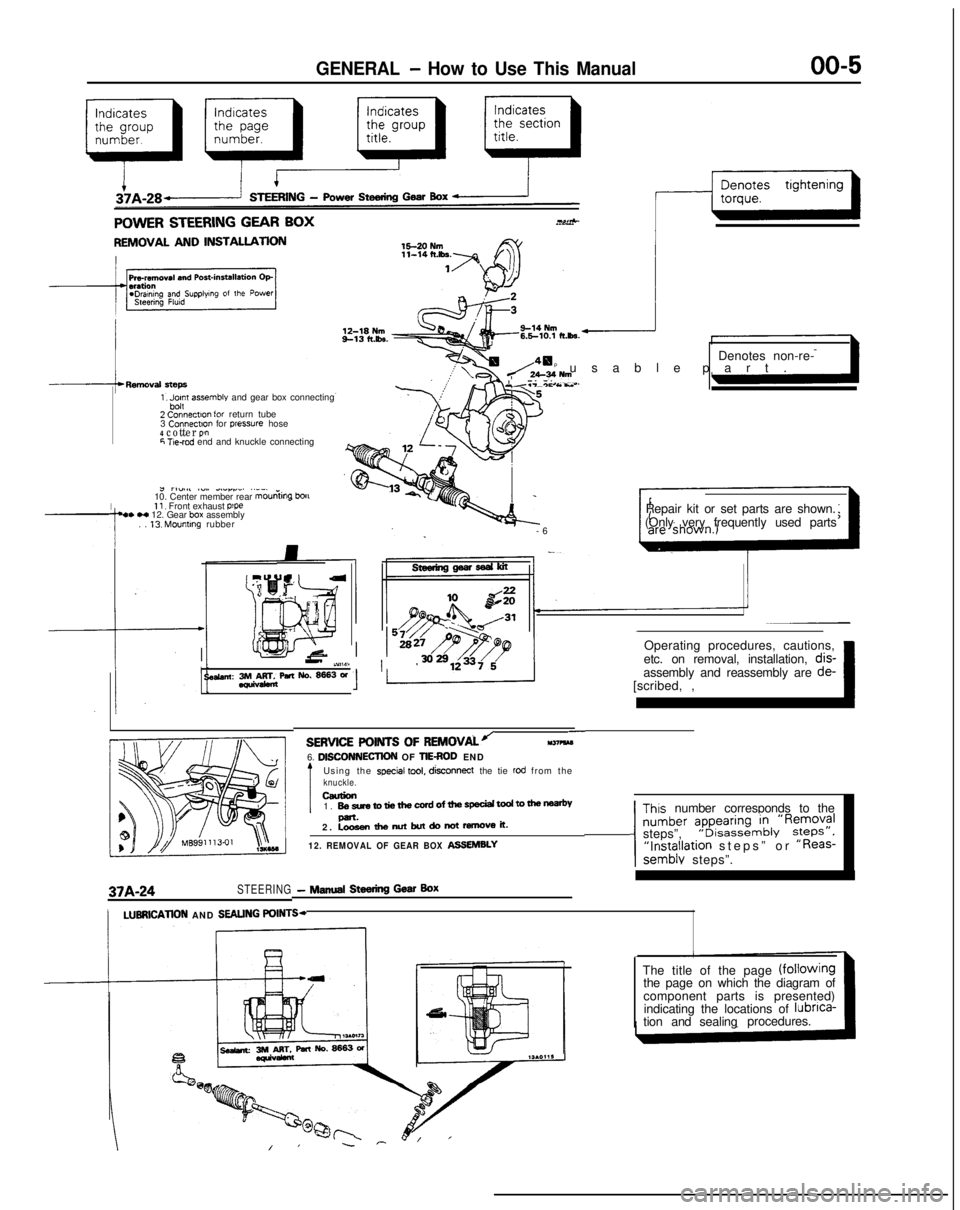
REMOVAL AND INSTALLATION
1, Jpn assemble and gear box connecting
2 Connectlo” for return tube
3 Connectm
for pressure hose4 cotter P!”6 T!e-rod end and knuckle connecting
I
J rl”.#l ~“,. dLlrr_. ..__
10. Center member rear mouniing
bou11, Front exhaust p’pe4. H 12. Gear box assembly
. . 13. Mounting rubber Denotes non-re-
p usable part
.
Y.T-*c As..
-
6
Repair kit or set parts are shown.
(Only very frequently used parts
Operating procedures, cautions,
II-’ iY,W11 ’etc. on removal, installation, dis-
se&an: 3rM&rr&paNo.~3W[scribed, ,~ 1assembly and reassembly are
de-
37A-24STEERING- NINA Steering Gear Box
-SERVICE POINTS OF
REMOVALJll37?kM6. DlSCONNECllON OF TIEROD END
Using the special tool, disconnect
the tie rod from theknuckle.ceurion1. BesretotiethewrdofthespeciaitodtomenP-.2. Loosenthenutbutdonotremoveit.
12. REMOVAL OF GEAR BOX ASSEMBLY
Thus number corresponds to the
number ?pyi:,“~&‘R~;;?Isteps”,“Installation steps” or “Reas-semblv steps”.
/LUBRlCATlON AND SEALING POINTS-
The title of the page (fOilOWingthe page on which the diagram of
component parts is presented)
indicating the locations of lubnca-
tion and sealingprocedures.
Page 8 of 1273
00-6GENERAL - How to Use This Manual
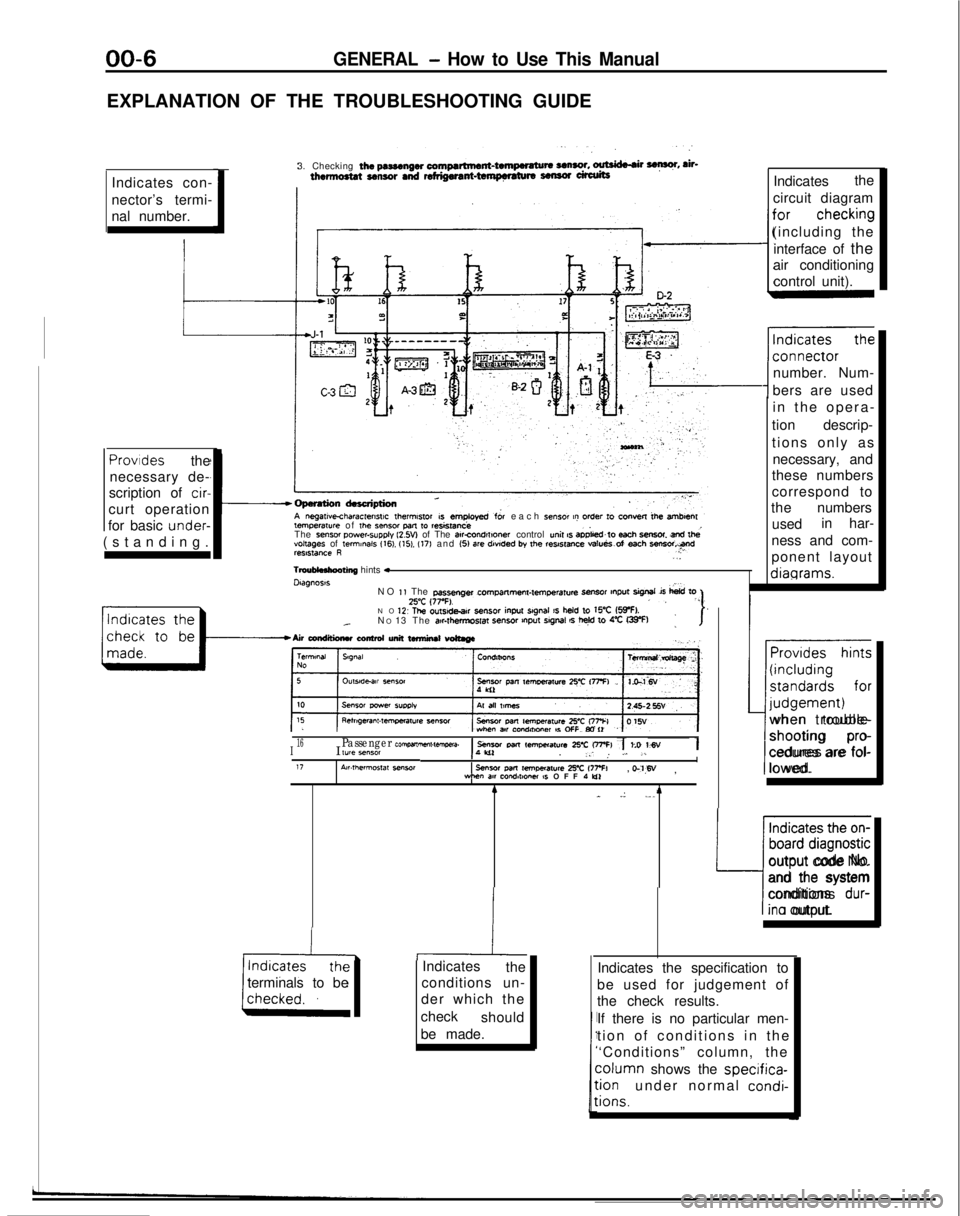
EXPLANATION OF THE TROUBLESHOOTING GUIDEIndicates con-
nector’s termi-
nal number. 3. Checking
the pasmngw compartment-twnpwatu* UnSO!. ~ F, ah-thermo8tat sensor and refdgwant-tempnaturs sensor ufalitsIndicates
the
circuit diagram
(including the interface of the
air conditioning
control unit).
number. Num-
bers are used temperawe
of
the Sensor pm
to resistanceeach sensor t? order to convest lb+ amben
The sense, power-supply l2.W of The atrcOnd,f,oner control unit s aD&d~to each SmSOt snd lhevoltages of te,mmaIs 116). (151. (17) and (51 are
dwded by the reslstme va!ueS.of each ““Freelstance R..
TmuMnhooting
hints *Dtagnoss
in the opera
-
tion descrip-
tions only as necessary, and
these numbers
correspond to
the numbers
used in har-
ness and com-
ponent layout diagrams.Provides
the
necessary de-
scription of
cir-
curt operation
for basic under-
(standing.
NO
1, The passenger cPrrlpmme”l-lemperatu4
-r tnput sigrml is
hid toZ’C (77-F).,, “”NO 1’2 The ou~sde.ar sensor
inpu
srgnal IS held to WC (5IpF).._N
O 13 The air#t,?,mpSf~ SenSO, VlPut SlgMl 6 t+ 10 4% G33-F):I-Airwndtlimluconhdunittwmirutwtmge
~~
I16I lYle *“MIPassenger com,wnme”t-tawa.1 sensor Parr lem,mat”r~ 25-c OFFI 7 to WV1,‘W. _: ,. L. .LI17A~r.,hermos,at seworsensor
Pm
remoeraure 2% 177% WM”
m cQndlt*Ow IS OFF 1 Lo, o-‘l,W
,
terminals to be 4
_
.: ._. 4
-hiIndicates
the
conditions un-
der which the
check should
be made. Provides hints
(including
standards for
I-- judgement)
when trouble-
shooting
pro-
cedures are fol-
lowed.
Indicates the on-
board diagnostic
L:
output code No.
and the system
conditions
dur-
ina output.
Indicates the specification to
be used for judgement of
the check results.
If there is no particular men-
tion of conditions in th
e
‘Conditions” column, the column
shows the
specifica-:ionunder normal condi-
:ions.
Page 9 of 1273
GENERAL - How to Use This Manual00-7
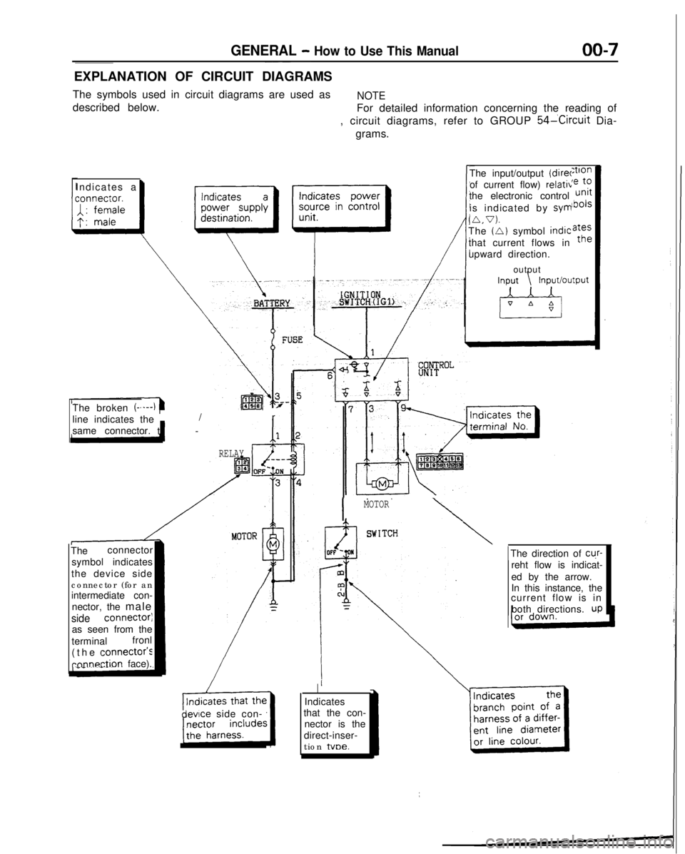
EXPLANATION OF CIRCUIT DIAGRAMS
The symbols used in circuit diagrams are used as
NOTE
described below. For detailed information concerning the reading of
, circuit diagrams, refer to GROUP
54lCircuit Dia-
grams.
Indicates
a
I
The input/output (direr
of current flow) relativ
the electronic control
is indicated by sym
(A.V).The (A) symbol
indic
that current flows in
upward direction.
output
The broken
(-.
line indicates the t
-
/r
same connector.
The connector
symbol indicates
the device side
connector (for an
intermediate con- nector, the male
side connectorj
as seen from the
terminal fronl
(the
connectois
rnnnection face).
RELAY
devce side con-
I
MOTOR
\
\
Indicates
that the con- nector is the
direct-inser-
tion tvoe.The direction of
cu.r-
reht flow is indicat-
ed by the arrow.
In this instance, the
current flow is in
both directions.
UP
Page 72 of 1273
ENGINE
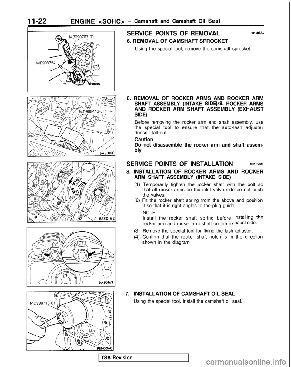
SERVICE POINTS OF REMOVALMllHBAL
6. REMOVAL OF CAMSHAFT SPROCKET
Using the special tool, remove the camshaft sprocket.
8. REMOVAL OF ROCKER ARMS AND ROCKER ARM
SHAFT ASSEMBLY (INTAKE SIDE)/S. ROCKER ARMS
AND ROCKER ARM SHAFT ASSEMBLY (EXHAUST
SIDE)
Before removing the rocker arm and shaft assembly, use
the special tool to ensure that the auto-lash adjuster doesn’t fall out.
Caution
Do not disassemble the rocker arm and shaft assem-
bly.
SERVICE POINTS OF INSTALLATIONMllHCAM
8. INSTALLATION OF ROCKER ARMS AND ROCKER
ARM SHAFT ASSEMBLY (INTAKE SIDE)
(1) Temporarily tighten the rocker shaft with the bolt so that all rocker arms on the inlet valve side do not pushthe valves.
(2) Fit the rocker shaft spring from the above and position it so that it is right angles to the plug guide.
NOTE
Install the rocker shaft spring before installinn the
rocker arm and rocker arm shaft on the ex haust side.
7.
(3)
(4)
Remove the special tool for fixing the lash adjuster.
Confirm that the rocker shaft notch is in the direction
shown in the diagram.
INSTALLATION OF CAMSHAFT OIL SEAL
Using the special tool, install the camshaft oil seal.
TSB Revision
Page 128 of 1273
ENGINE
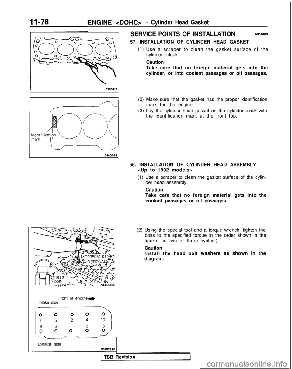
SERVICE POINTS OF INSTALLATIONMllJDAN
57. INSTALLATION OF CYLINDER HEAD GASKET
(1) Use a scraper to clean the gasket surface of the
cylinder block.
Ident i f ido c\ (Imark\ OlAOO38
Front of
engine+Intake side
.miJ
Exhaust side Caution
Take care that no foreign material gets into the cylinder, or into coolant passages or oil passages.
(2) Make sure that the gasket has the proper identification mark for the engine.
(3) Lay the cylinder head gasket on the cylinder block with the identification mark at the front top.
56. INSTALLATION OF CYLINDER HEAD ASSEMBLY
(1) Use a scraper to clean the gasket surface of the cylin- der head assembly.
Caution
Take care that no foreign material gets into the
coolant passages or oil passages.
(2) Using the special tool and a torque wrench, tighten the bolts to the specified torque in the order shown in the
figure. (in two or three cycles.)
Caution
Install the head bolt washers as shown in the
diagram.
Page 143 of 1273
13-1
FUEL
CONTENTSM’ISAA--
AUTO-CRUISE CONTROL SYSTEM.............
.
332
AUTO-CRUISE CONTROL ............................. 408
SERVICE ADJUSTMENT PROCEDURES .................397
Accelerator Cables
inspectron and Adjustment ........
.
398 Auto-cruise
Control System Inspection
..............397
Individual Parts Inspection ......................
401SPECfAL
TOOLS
.....................................
333
SPECIFICATIONS .................................... 332
TROUBLESHOOTING ................................. 334
Auto-cruise Control Components Location ..........368
Auto-cruise Control
Related Harnesses
..........365
Check Chart
Check Chart
Circuit Diagram ................................
371input Checking................................
.
366
On-board Diagnostic Checking ......................
361Troubleshooting Quick-reference Chart
.
334
Troubleshooting Quick-reference Chart
ENGINE CONTROL...............................
.
328
ENGINE CONTROL ..................................
330
SERVICE ADJUSTMENT PROCEDURES .................329
Accelerator Cable inspectron and Adjustment
...........329
Accelerator Switch Inspection and Adjustment ..........329
SPECIFICATIONS ....................................
328
TROUBLESHOOTlNG................................
.
328
Accelerator
Cable and Accelerator Pedal .............
.
328
FUEL SYSTEM
FUEL FILTER .........................................
327
FUEL LINE AND VAPOR LINE
.
326
FUEL LINE AND VAPOR LINE
.
324
FUEL TANK
.
322
FUELTANK
.
318
GENERAL INFORMATION ............................ 196
ON-VEHICLE INSPECTION OF MFI
COMPONENTS
......251
Air Conditioning Switch and A/C Compressor Clutch Relay .....................................
285
Barometric Pressure Sensor .................... 266
Boost Meter
311Camshaft Position Sensor ........................
.
277Closed Throttle Position Switch
.....................
.
274
Component Location .............................
251Components Inspection Pocedure
................. 255
Crankshaft Position Sensor ..................... 280EGR
Solenord
...................
.
307EGR Temperature Sensor
.............
.
288Engrne Control Module Power Ground
................
.
257
Engine Coolant Temperature Sensor ..................
268Evaporative Emission Purge Solenoid .................
.
307
Fuel Pressure Solenoid
307Fuel Pressure Test...............................
.
312
Fuel Pump ...................................... 258
Heated Oxygen Sensor ............................ 290
Idle Air Control Motor (Stepper Motor) ................
238Ignition Coil and Ignition Power Transistor .............
.
302
Ignition Switch-ST .................................. 284
Ignition Switch-ST and Park/Neutral Position Switch .....284
Injectors .......................................
295Inspection of Engine Control Module Terminal
Voltage .......................................
.
315
Intake Air Temperature Sensor .......................263
Knock Sensor
Power Steering Pressure Switch ......................
284Power Supply and Ignition Switch ...................
.
255Resistor
..............................
.
298Terminal Voltage Check Chart
......................
.
315Throttle Position Sensor
..........................
.
270Turbocharger Waste Gate Solenoid
.........
.
309 Vehicle
Speed Sensor
............................... 284
Volume Air Flow Sensor ............................
261SERVICE ADJUSTMENT PROCEDURES ...............
.
245
Basic
idle Speed Adjustment .......................
.
245
Closed Throttle Position Switch (Fixed
SAS)Adjustment ......................................
.
250
Curb
Idle Speed Inspection
..........................245Throttle Body (Throttle Valve Area) Cleaning
...........
.
248Throttle Position Sensor Adjustment
..................
.
248
SPECIALTOOLS...................................
.
204
SPECIFICATIONS ...................................
201TROUBLESHOOTING ...............................
.
205
Check Engine/Malfunction Indicator Lamp ..............205
Circuit Diagram .................................... 214
Clear Memory of Diagnostic Trouble Code .............
211Explanation and Precaution Related to Harness
Checking ......................................
.
205Explanation of Troubleshooting Procedures
............
.
205Failsafe/Back-up Functions List
.....................
.
211Fuel tank and Fuel Line
............................
.
244
Read Out Diagnostic Trouble Code ...................
211Troubleshooting Table
.............................
.
208(CONTINUED ON NEXT PAGE)