Page 251 of 1273
FUEL SYSTEM - Fuel Tank13-109
FUEL TANK MlSGA-
{EMOVAL AND INSTALLATION
r
30-40 N
m
22-?9
ft.lbs.
2-3 Nm
1.4-2.2,ft.lbs.IP
2-3 N
m
1.4-2.2 f-Lit
6.5-10
ft.lbs.
!I17-26 N
m
12- 19
ft.lbs.
Removal steps 1. Fuel tank filler tube cap
2. Drain plug
l + 3. Return hosel + 4. Vapor hose5. Fuel gauge unit connector
6. Electrical fuel pump connector
l +7. High pressure hose to fuel pump connection
l + 8. Filler hosel +9. Vapor hosel + 10. Self-locking nut11, Tank band stay12. Tank band13. Fuel tankl 4 14. Vapor hosee+ 15. Fuel tank pressure control valve
16. Fuel gauge unit
17. Electrical fuel pump
18. Fuel tnak filler tube
i8
03A0142
Caution
When disconnecting the high pressure fuel hose, cover
the hose connection with rags to prevent splash of fuel that could be caused by some residual pressure in the
fuel pipe line.
TSB Revision
Page 460 of 1273
13-318FUEL SYSTEM - Fuel Tank
FUEL TANK MIBGA-AREMOVAL
AND INSTALLATION
3
Removal steps 03A0284
1. Fuel tank filler tube cap2. Drain plugl + 3. Return hosel +
4. Vapor hose
5. Fuel gauge unit connector
6. Electrical fuel pump connector
l 47. High pressure hose to fuel pumpconnectionI)+ 8. Filler hose~1Weasuerment of Fuel PressureH 9. Vapor hose+4 10. Self-locking nut1 I. Tank band stay12. Tank band
13. Fuel tank
I)+ 14. Vapor hose
l + 15. Fuel tank pressure control valveCaution
16. Fuel gauge unitWhen disconnecting the high pressure fuel hose, cover
17. Electrical fuel pumpthe hose connection with rags to prevent splash of fuel
18. Fuel tank filler tube that could be caused by some residual pressure in thefuel pipe line.
TSB Revision1
Page 464 of 1273
13-322FUEL SYSTEM - Fuel Tank
FUEL TANK MlJGA-B
REMOVAL AND INSTALLATION
Sealant:
3M ATD Part No.8625or equivalent
30-40 Nm
22-29 ftlbs.
5
\\
\I@Release of Residual Pressure from High
11aMeasurement of Fuel Pressure
l-2 Nm0.7-1.4 ftlbs.\30-40 Nm
22-29 ftlbs.
\h
21-31 N/m15-22
ftlbs.
Removal steps
1. Fuel tank filler tube cap2. Drain plug3. Return hose (Refer to P.13-319.)4. Vapor hose 5. Fuel high pressure hose (Refer toP.13-319.1
17-2
6
12-1s
;~\*3~o,,.
Es.6
6. Filler
ho&7. Vapor hose (Refer to P.13-319.)8. Protector
9. Hole cover
IO. Self-locking nut11. Fuel tank
12. Fuel tank pressure control valve (Refer toP.13-319.)
13. Fuel pump and gauge assembly14. Fuel tank filler tube Caution
When disconnecting the high pressure fuel hose, cover
the hose connection with rags to prevent splash of fuel
that could be caused by some residual pressure in the
fuel pipe line.
TSB Revision
Page 1108 of 1273

REAR SUSPENSION - Rear Suspension Assembly34-27
12A0222
12A.0221
,
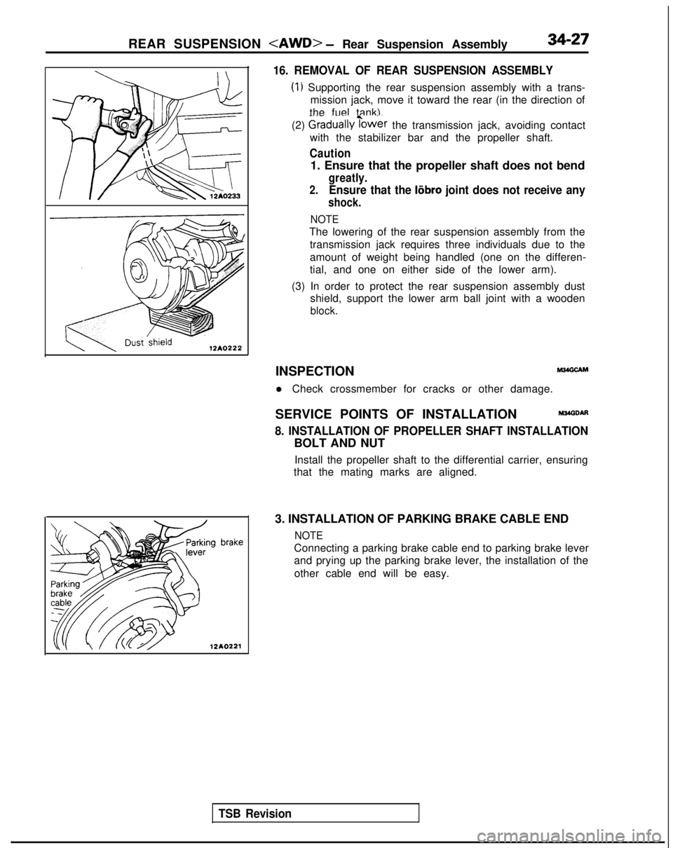
16. REMOVAL OF REAR SUSPENSION ASSEMBLY
(1) Supporting the rear suspension assembly with a trans-
mission jack, move it toward the rear (in the direction of
the fuel tank).
(2)
Graduallyibwer the transmission jack, avoiding contact
with the stabilizer bar and the propeller shaft.
Caution
1. Ensure that the propeller shaft does not bend
greatly.
2.Ensure that the liibro joint does not receive any
shock.
NOTE
The lowering of the rear suspension assembly from the
transmission jack requires three individuals due to the
amount of weight being handled (one on the differen-
tial, and one on either side of the lower arm).
(3) In order to protect the rear suspension assembly dust shield, support the lower arm ball joint with a wooden
block.
TSB Revision
INSPECTIONM24GCAM
l Check crossmember for cracks or other damage.
SERVICE POINTS OF INSTALLATION
M34GDAfl
8. INSTALLATION OF PROPELLER SHAFT INSTALLATION
BOLT AND NUT Install the propeller shaft to the differential carrier, ensuring
that the mating marks are aligned.
3. INSTALLATION OF PARKING BRAKE CABLE END
NOTE
Connecting a parking brake cable end to parking brake lever
and prying up the parking brake lever, the installation of the other cable end will be easy.