1989 MITSUBISHI GALANT clock
[x] Cancel search: clockPage 58 of 1273
II-8ENGINE
8 VALVE
W Tlmlng belt side
il6
16
727
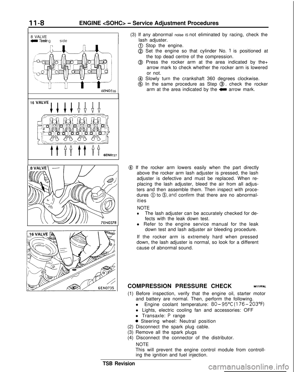
(3) If any abnormal noise IS not eliminated by racing, check the
lash adjuster.
@ Stop the engine.
@ Set the engine so that cylinder No. 1 is positioned at
the top dead centre of the compression.
@ Press the rocker arm at the area indicated by the+ arrow mark to check whether the rocker arm is lowered
or not.
@ Slowly turn the crankshaft 360 degrees clockwise.
@ In the same procedure as Step 0, check the rocker
arm at the area indicated by the
0 arrow mark.
@ If the rocker arm lowers easily when the part directly
above the rocker arm lash adjuster is pressed, the lash
adjuster is defective and must be replaced. When re-
placing the lash adjuster, bleed the air from all adjus-
ters and then assemble them. Then inspect with proce-
dures
@ to 0, and confirm that there are no abnormal-
ities
NOTE
lThe lash adjuster can be accurately checked for de-
fects with the leak down test.
l Refer to the engine service manual for the leak down test and lash adjuster air bleeding procedure.
If the rocker arm is extremely hard when pressed
down, the lash adjuster is normal, so look for a different
cause of abnormal sound.
COMPRESSION PRESSURE CHECK
MllFFAL
(1) Before inspection, verify that the engine oil, starter motor and battery are normal. Then, perform the following.
l Engine coolant temperature:
80- 95°C
(176- 203°F)
l Lights, electric cooling fan and accessories: OFF
l Transaxle:
P range
0 Steering wheel: Neutral position
(2) Disconnect the spark plug cable.
(3) Remove all the spark plugs
(4) Disconnect the connector of the distributor.
NOTE
This will prevent the engine control module from controll- ing the ignition and fuel injection.
TSB Revision
Page 60 of 1273
II-IOENGINE
(3) Remove the PCV hose from the PCV valve and attach a
vacuum gauge.
(4) Check that the negative pressure at the intake manifold
during idle revolution is normal.
Standard value:
(8 VALVE>Approx. 500 mmHg (20 in.Hg)
<16VALVE>Approx. 510 mmHg (20 in.Hg)
(5) If outside the standard value, isolate the cause by referring
to the following table and repair the fault.
Symptom
CauseRemed
y
l The vacuum gauge reading is less than l Ignition timing is retarded.l Adjust the ignition timing.
standard value, but the pointer is
stable.
l The vacuum gauge pointer swings l The gas mixture is excessivelyl Check
Multiport Fuel Injection
slowly.rich.system.
l The vacuum gauge pointer drops irre-
l The gas mixture is excessively
l Check
Multiport Fuel Injectiongularly.lean.system.
l The vacuum gauge pointer drops inter-
0 Incomplete close contact of in-0 Check and repair the valve.mittently to 30 to 160
mmHg
(1.2 to take and exhaust valve seats.
6.3 in.Hg).
l The vacuum gauge pointer drops sud-l Broken cylinder head gasketl ,Replace cylinder head gasket. denly
from the normal reading to 250 mmHg
(9.8 in.Hg). then returns to
normal.
/ OlR0175
condition.
Timina mark
‘timing mark._*-
Camshaft sprocket TIMING BELT TENSION ADJUSTMENT
(8 VALVE>MllFGCEa
There are 2 access holes in the timing belt front lower cover.
These can be used to readjust the tension of the timing belt by
the following procedure without removing the timing belt front lower cover. However, timing belt “B”, which drives the right
silent shaft, cannot be adjusted unless the cover is removed. (1) Turn the steering wheel all the way to the left.
(2) Remove the left side undercover panel.
NOTE
This work is done so that the crankshaft can be turned.
(3) Place a piece of wood against the engine oil pan and jac
k
up.(4) Remove the engine mounting bracket.
(5) Remove the timging belt front upper cover.
(6) Remove the four spark plugs.
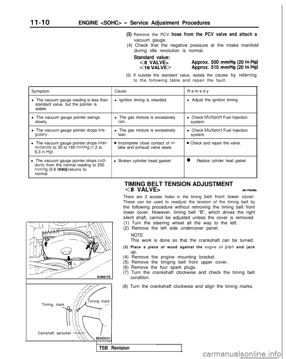
(7) Turn the crankshaft clockwise and check the timing belt
(8) Turn the crankshaft clockwise and align the timing marks.
TSB Revision1
Page 61 of 1273
ENGINE
Access
cover
,-
(0 a0
<
0 0
0 0
0
101 II0221
Access cover
Screwdriver slot
3EN075
(9) Remove the air conditioning drive belt and the generator drive belt.
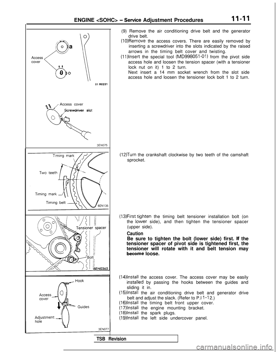
(10)Removle the access covers. There are easily removed by
inserting a screwdriver into the slots indicated by the raised
arrows in the timing belt cover and twisting. (1l)lnset-t
the special tool (MD998051-01)
from the pivot side
access hole and loosen the tension spacer (with a tensioner lock nut on it) 1 to 2 turn.
Next insert a 14 mm socket wrench from the slot side
access hole and loosen the tensioner lock bolt 1 to 2 turn.
(12)Turn the crankshaft clockwise by two teeth of the camshaft
sprocket.
(13)First ticjhten the timing belt tensioner installation bolt (on
the
lo&er side), and then tighten the tensioner spacer
(upper side).
Caution
Be sure to tighten the bolt (lower side) first. lf the
tensioner spacer of pivot side is tightened first, the
tensioner will rotate with it and belt tension may
becorn; loose.
(14)lnstall the access cover. The access cover may be easily
installeNd by passing the hooks between the guides and
sliding it in.
(15)lnstall the air conditioning drive belt and generator drive
belt and adjust the slack. (Refer to P.l
l-l 2.)
(16)lnstall the timing belt front upper cover.
(17)lnstall the engine mounting bracket.
(18)lnstall the spark plugs.
(19)lnstall the left side undercover panel.
TSB Revision
Page 86 of 1273
11-36
ENGINE
Timing mark
\
Camshaft sprocket
;/
i
\
IlEN0017
Tit
e
I;
OlAO550
01A0551
SERVICE POINTS OF REMOVALMllKBDF
2. REMOVAL OF ENGINE MOUNT BRACKET
(1) Jack up the vehicle after placing a wooden block
between the jack and the engine’s oil pan.
Caution
Jack up carefully so as not to apply an excessive
load to the various parts.
(2) Remove the engine mount bracket.
20. REMOVAL OF TIMING BELT
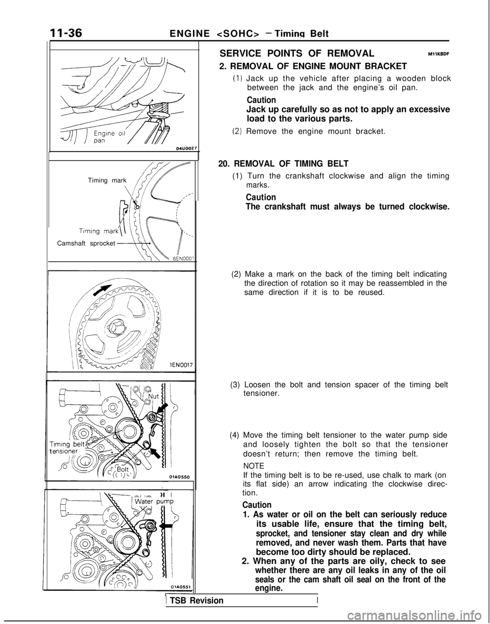
(1) Turn the crankshaft clockwise and align the timing
marks.
Caution
The crankshaft must always be turned clockwise.
(2) Make a mark on the back of the timing belt indicating the direction of rotation so it may be reassembled in the
same direction if it is to be reused.
(3) Loosen the bolt and tension spacer of the timing belt tensioner.
(4) Move the timing belt tensioner to the water pump side and loosely tighten the bolt so that the tensioner
doesn’t return; then remove the timing belt.
NOTE
If the timing belt is to be re-used, use chalk to mark (on
its flat side) an arrow indicating the clockwise direc-
tion.
Caution
1. As water or oil on the belt can seriously reduce
its usable life, ensure that the timing belt,
sprocket, and tensioner stay clean and dry while
removed, and never wash them. Parts that have
become too dirty should be replaced.
2. When any of the parts are oily, check to see
whether there are any oil leaks in any of the oil
seals or the cam shaft oil seal on the front of the
engine.
1 TSB Revision
Page 90 of 1273
II-40ENGINE
OlRO372
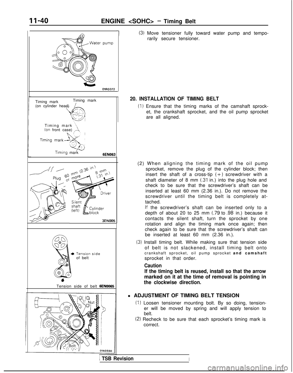
1(3) Move tensioner fully toward water pump and tempo-rarily secure tensioner.
Timing mark Timing mark
(on cylinder head)
Timing mark
“1(on front case) ,A.
Timing mark6EN063
3ENOO5
Tensiorof belt-I sid
e
Tension side of belt
6EN0065
20. INSTALLATION OF TIMING BELT
(1) Ensure that the timing marks of the camshaft sprock- et, the crankshaft sprocket, and the oil pump sprocket
are all aligned.
(2) When aligning the timing mark of the oil pump sprocket, remove the plug of the cylinder block; then
insert the shaft of a cross-tip
(+) screwdriver with a
shaft diameter of 8 mm
(.31 in.) into the plug hole and
check to be sure that the screwdriver’s shaft can be
inserted at least 60 mm (2.36 in.). Do not remove the
screwdriver until the timing belt is completely at-
tached.
If the screwdriver’s shaft can be inserted only to a
depth of about 20 to 25 mm
(.79 to .98 in.) because it
contacts the silent shaft, turn the sprocket by one rotation and align the timing mark once again; then
check again to be sure that the screwdriver’s shaft can be inserted at least 60 mm (2.36 in.).
(3) Install timing belt. While making sure that tension side
of belt is not slackened, install timing belt onto
crankshaft sprocket, oil pump sprocket and camshaf
t
sprocket in that order.
Caution
If the timing belt is reused, install so that the arrow
marked on it at the time of removal is pointing in
the clockwise direction.
l ADJUSTMENT OF TIMING BELT TENSION
(1) Loosen tensioner mounting bolt. By so doing, tension- er will be moved by spring and will apply tension to
belt.
(2) Recheck to be sure that each sprocket’s timing mark iscorrect.
1 TSB RevisionI
Page 91 of 1273
ENGINE
I
I
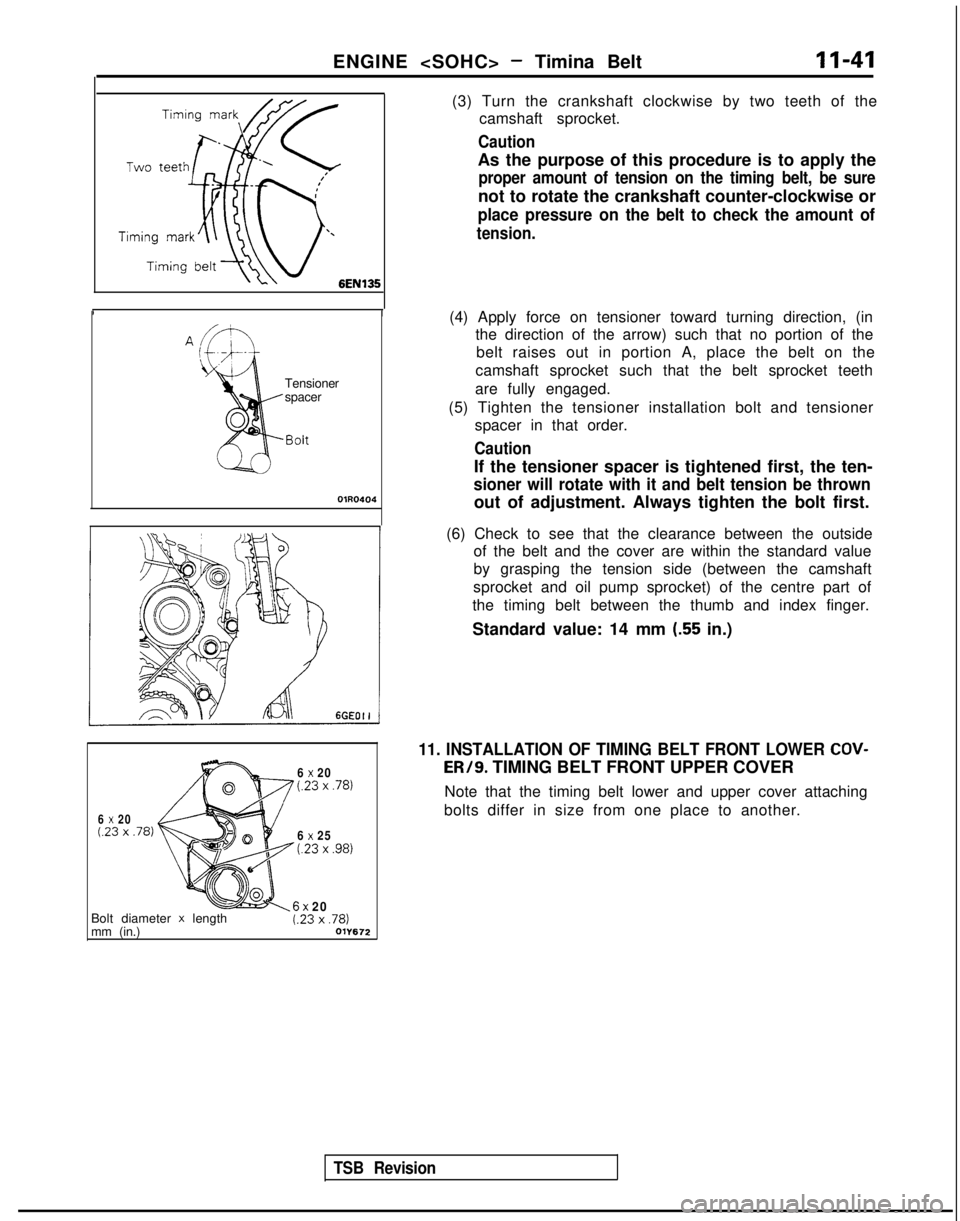
(3) Turn the crankshaft clockwise by two teeth of the
camshaft sprocket.
Caution
As the purpose of this procedure is to apply the
proper amount of tension on the timing belt, be sure
not to rotate the crankshaft counter-clockwise or
place pressure on the belt to check the amount of
tension.
Tensioner
spacer
OlR0404
(4) Apply force on tensioner toward turning direction, (inthe direction of the arrow) such that no portion of the
belt raises out in portion A, place the belt on the
camshaft sprocket such that the belt sprocket teeth
are fully engaged.
(5) Tighten the tensioner installation bolt and tensioner spacer in that order.
Caution
If the tensioner spacer is tightened first, the ten-
sioner will rotate with it and belt tension be thrown
out of adjustment. Always tighten the bolt first.
TSB Revision
(6) Check to see that the clearance between the outside of the belt and the cover are within the standard value
by grasping the tension side (between the camshaft
sprocket and oil pump sprocket) of the centre part of
the timing belt between the thumb and index finger.
Standard value: 14 mm
(.55 in.)
6 x 20(23 x .78)
6 x 20(23 x .78)
6 x 25t.23 x ,981
11. INSTALLATION OF TIMING BELT FRONT LOWER COV- ER/9.
TIMING BELT FRONT UPPER COVER
Note that the timing belt lower and upper cover attaching
bolts differ in size from one place to another.
Bolt diameter
x length
mm (in.)6x 20t.23 x ,781011672
Page 94 of 1273
ENGINE
A Timing
mark
Timingmark
mark
-/Crank&aft swocketOlA0667 lEN0017SERVICE POINTS OF REMOVAL
MllKBDG
2. REMOVAL OF ENGINE MOUNT BRACKET
(1) With a wooden block placed against the oil pan part ofthe engine, jack up the vehicle.
Caution
Jack up gently, so as not to apply a load to the va-
rious parts.
(2) Remove the engine mount bracket.
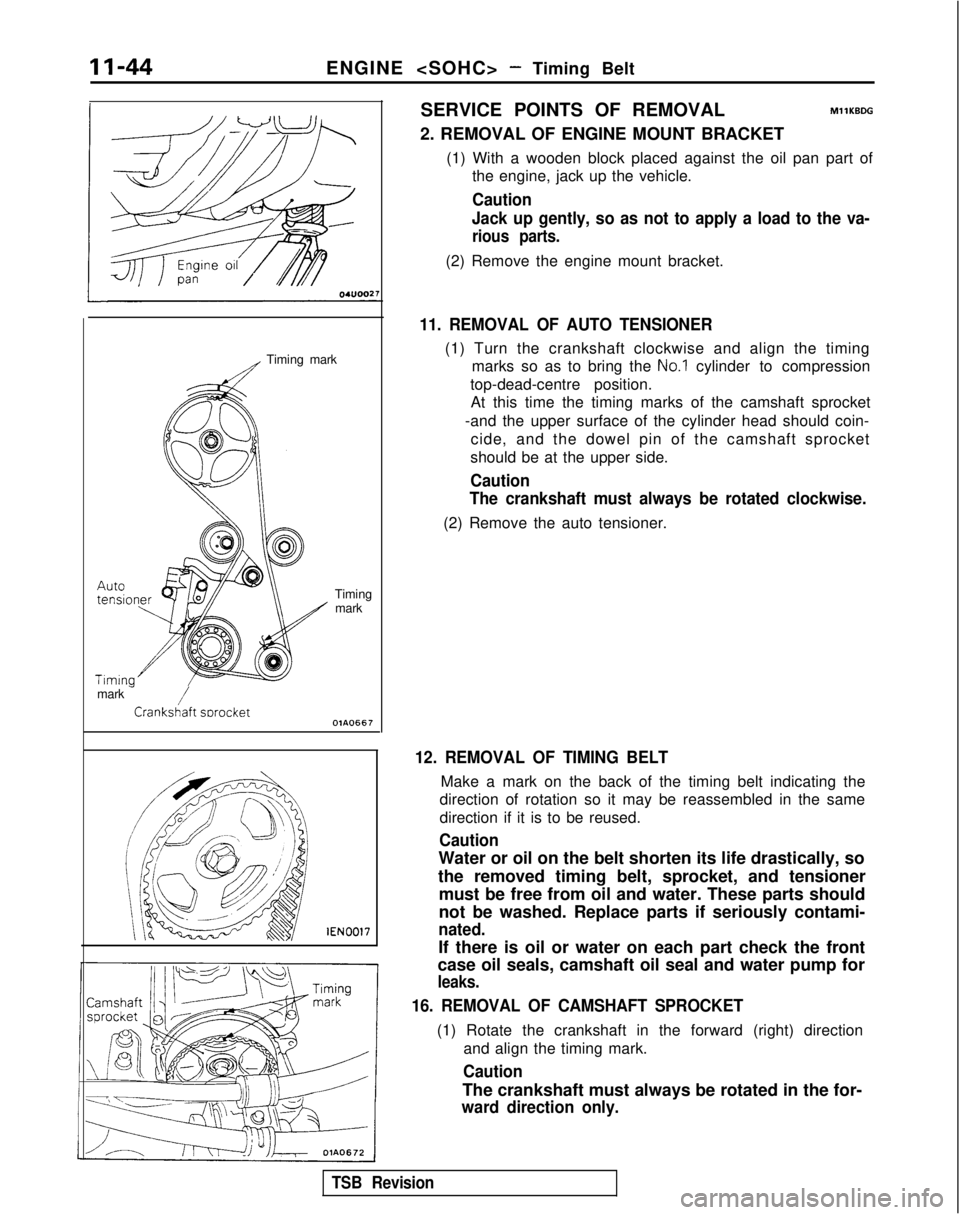
11. REMOVAL OF AUTO TENSIONER
(1) Turn the crankshaft clockwise and align the timing marks so as to bring the
No.1 cylinder to compression
top-dead-centre position. At this time the timing marks of the camshaft sprocket
-and the upper surface of the cylinder head should coin- cide, and the dowel pin of the camshaft sprocket
should be at the upper side.
Caution
The crankshaft must always be rotated clockwise.
(2) Remove the auto tensioner.
12. REMOVAL OF TIMING BELT
Make a mark on the back of the timing belt indicating the
direction of rotation so it may be reassembled in the same
direction if it is to be reused.
Caution
Water or oil on the belt shorten its life drastically, so
the removed timing belt, sprocket, and tensioner must be free from oil and water. These parts should
not be washed. Replace parts if seriously contami-
nated.
If there is oil or water on each part check the front
case oil seals, camshaft oil seal and water pump for
leaks.
16. REMOVAL OF CAMSHAFT SPROCKET
(1) Rotate the crankshaft in the forward (right) direction
and align the timing mark.
Caution
The crankshaft must always be rotated in the for-
ward direction only.
TSB Revision
Page 101 of 1273
ENGINE
r
L Camshaft sprocket
Idler
pulley
/Oil pumpOlA0668
sprocket
6EN0175
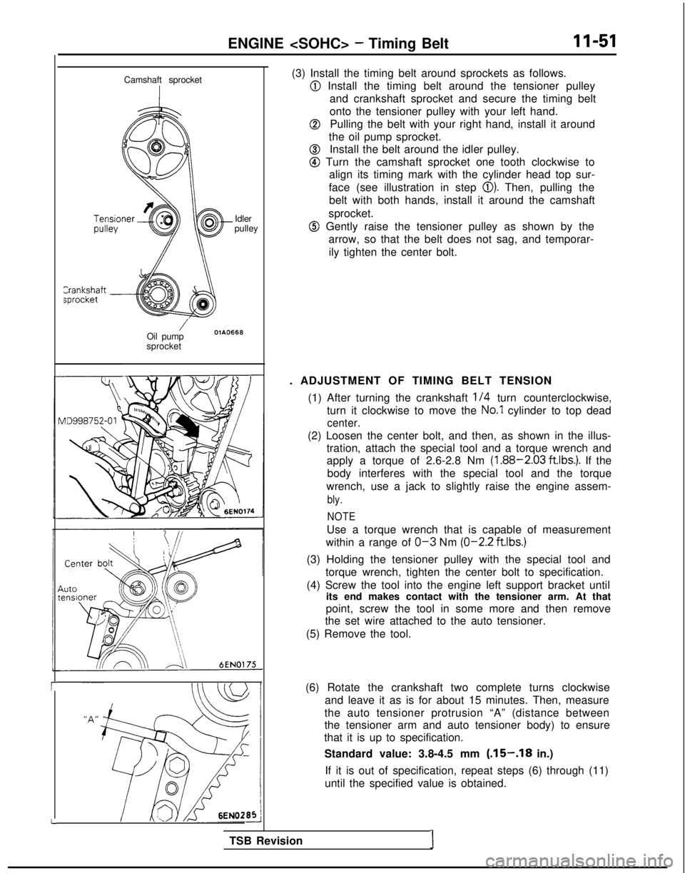
(3) Install the timing belt around sprockets as follows.
@ Install the timing belt around the tensioner pulley
and crankshaft sprocket and secure the timing belt
onto the tensioner pulley with your left hand.
@Pulling the belt with your right hand, install it around
the oil pump sprocket.
@Install the belt around the idler pulley.
@ Turn the camshaft sprocket one tooth clockwise to align its timing mark with the cylinder head top sur-
face (see illustration in step
0). Then, pulling the
belt with both hands, install it around the camshaft
sprocket.
@ Gently raise the tensioner pulley as shown by the arrow, so that the belt does not sag, and temporar-
ily tighten the center bolt.
. ADJUSTMENT OF TIMING BELT TENSION (1) After turning the crankshaft
l/4 turn counterclockwise,
turn it clockwise to move the
No.1 cylinder to top dead
center.
(2) Loosen the center bolt, and then, as shown in the illus- tration, attach the special tool and a torque wrench and
apply a torque of 2.6-2.8 Nm
(1.88-2.03 ft.lbs.). If the
body interferes with the special tool and the torque
wrench, use a jack to slightly raise the engine assem-
bly.
NOTE
Use a torque wrench that is capable of measurement
within a range of
O-3 Nm (O-2.2
ftlbs.)
(3) Holding the tensioner pulley with the special tool and
torque wrench, tighten the center bolt to specification.
(4) Screw the tool into the engine left support bracket until its end makes contact with the tensioner arm. At that
point, screw the tool in some more and then remove
the set wire attached to the auto tensioner.
(5) Remove the tool.
(6) Rotate the crankshaft two complete turns clockwise and leave it as is for about 15 minutes. Then, measure
the auto tensioner protrusion “A” (distance between
the tensioner arm and auto tensioner body) to ensure
that it is up to specification.
Standard value: 3.8-4.5 mm
(.15-.18 in.)
If it is out of specification, repeat steps (6) through (11)
until the specified value is obtained.
TSB Revision
I