1989 MITSUBISHI GALANT clock
[x] Cancel search: clockPage 326 of 1273
13-184
On-Vehicle Inspection of MFI
FUEL SYSTEM (SOHC-16 VALVE> - Components
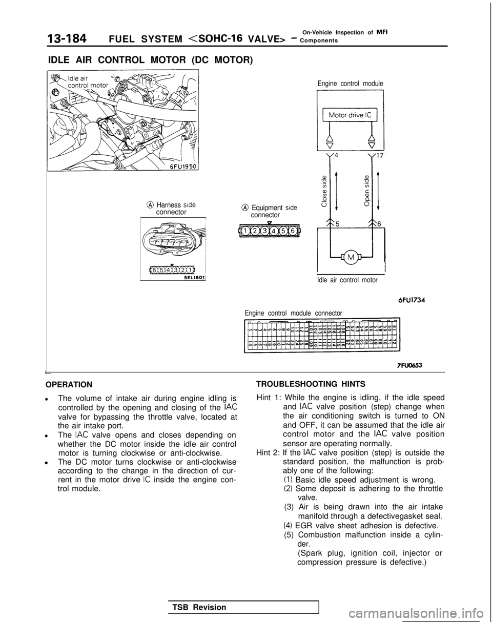
IDLE AIR CONTROL MOTOR (DC MOTOR)
@ Harness sideconnectorI L
[@Ex@ziJ 1
5ELWOlJ
j
e;
j 55ww3 )A’,’/
@ Equipment sideconnector
Engine control module
Idle air control motor
6FU1734
Engine control module connector
7FUCJG3
OPERATION
lThe volume of intake air during engine idling is controlled by the opening and closing of the
IAC
valve for bypassing the throttle valve, located at
the air intake port.
lThe IAC valve opens and closes depending on
whether the DC motor inside the idle air control motor is turning clockwise or anti-clockwise.
l The DC motor turns clockwise or anti-clockwise
according to the change in the direction of cur-
rent in the motor drive
IC inside the engine con-
trol module. TROUBLESHOOTING HINTS
Hint 1: While the engine is idling, if the idle speed and
IAC valve position (step) change when
the air conditioning switch is turned to ON
and OFF, it can be assumed that the idle air
control motor and the
IAC valve position
sensor are operating normally.
Hint 2: If the
IAC valve position (step) is outside the
standard position, the malfunction is prob-
ably one of the following: (I)
Basic idle speed adjustment is wrong.
(2) Some deposit is adhering to the throttle
valve.
(3) Air is being drawn into the air intake
manifold through a defectivegasket seal.
(4) EGR valve sheet adhesion is defective.
(5) Combustion malfunction inside a cylin-
der.
(Spark plug, ignition coil, injector or
compression pressure is defective.)
TSB Revision
Page 793 of 1273
AUTOMATIC TRANSAXLE - Service Adjustment Procedures23-87
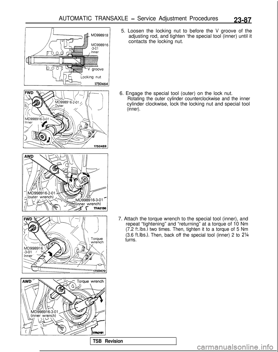
5. Loosen the locking nut to before the V groove of the
adjusting rod, and tighten ‘the special tool (inner) until it
contacts the locking nut.
6. Engage the special tool (outer) on the lock nut.
Rotating the outer cylinder counterclockwise and the inner
cylinder clockwise, lock the locking nut and special tool
(inner).
7. Attach the torque wrench to the special tool (inner), and repeat “tightening” and “returning” at a torque of 10 Nm
(7.2 ft.lbs.) two times. Then, tighten it to a torque of 5 Nm
(3.6
ft.Ibs.). Then, back off the special tool (inner) 2 to 2%
turns.
TSB Revision
Page 794 of 1273
23-88AUTOMATIC TRANSAXLE - Service Adjustment Procedures
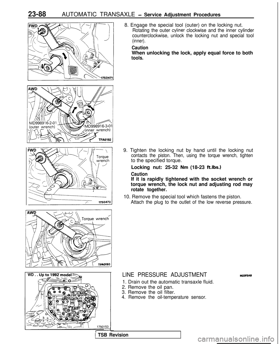
8. Engage the special tool (outer) on the locking nut.
Rotating the outer cyliner clockwise and the inner cylinder
counterclockwise, unlock the locking nut and special tool
(inner).
Caution
When unlocking the lock, apply equal force to both
tools.
WD . . . Up to 1992 model -
&@~o-&q
9. Tighten the locking nut by hand until the locking nut
contacts the piston. Then, using the torque wrench, tighten
to the specified torque.
Locking nut: 25-32
Nm (18-23 ft.lbs.)
Caution
If it is rapidly tightened with the socket wrench or
torque wrench, the lock nut and adjusting rod may
rotate together.
10. Remove the special tool which fastens the piston.
Attach the plug to the outlet of the low reverse pressure.
LINE PRESSURE ADJUSTMENT
1. Drain out the automatic transaxle fluid.
2. Remove the oil pan.
3. Remove the oil filter.
4. Remove the oil-temperature sensor.
J
1 TSB Revision
M23F9A9
Page 796 of 1273

AUTOMATIC TRANSAXLE - Service Adjustment Procedures
1_DTZii+!ilz$F~
I
\
B
-g----J a
----- .f-
iL (i
&Fgi
Tit\I;; ;gTjqy ?“,,,,,,
FWD . . . Up to MODEL 1990IOil pan gasketsurface
case0
1750435
7. Remove the valve body assembly. The manual valve can
come out, so be careful not to drop it.
8.Turn the adjustment screw of the regulator valve and adjust
so that the line pressure (kickdown brake pressure)
becomes the standard value.
When the adjustment screw is turned to the clockwise, the
line pressure becomes lower; when it is turned to
counter-clockwise, it becomes higher.
Standard value: 870-890 kPa (124-127 psi)
Oil pressure change for each turn of adjustment screw: 38
kPa (94 psi)
9. Check to be sure that the O-ring is installed on the upper
surface of the valve body at the place shown in the figure.
10. Replace the O-ring of the solenoid valve connector with a new one.
11. Install the valve body assembly to the case and then insert
the solenoid valve connector into the case. Be sure, at this
time, that the notched part of the connector faces as
shown in the figure.
Also be careful that the lead wiring isn’t caught.
TSB Revision
12. Replace the O-ring of the solenoid valve harness with a new one.
13. Tilt the solenoid valve harness over from the inner side of
the transaxle case to the harness grommet installation hole’
and install the harness grommet securely.
14. Install the harness grommet so that the lead wiring of the solenoid valve harness faces in the direction indicated by
the arrow in the illustration. (FWD . . . From MODEL
1990.5)
Page 875 of 1273
REAR AXLE
Matina marks/I
1
SERVICE ADJUSTMENT PROCEDURES
REAR AXLE TOTAL BACKLASH CHECKMZ’IFAAF
If the vehicle vibrates and produces a booming sound due to an
imbalance of the driving system, measure the rear axle total
backlash by the following procedures to see if the differential
carrier assembly requires removal.
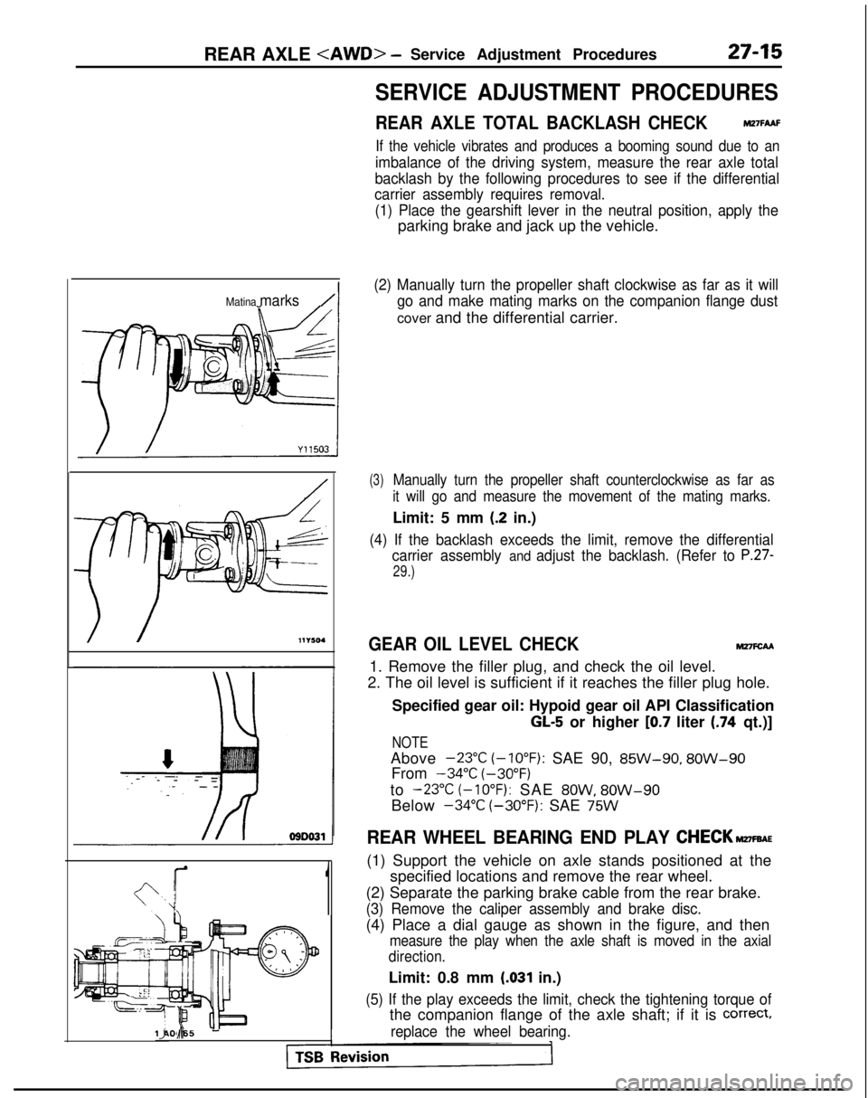
(1) Place the gearshift lever in the neutral position, apply the
parking brake and jack up the vehicle.
(2) Manually turn the propeller shaft clockwise as far as it will go and make mating marks on the companion flange dust
cover and the differential carrier.
(3)Manually turn the propeller shaft counterclockwise as far as
it will go and measure the movement of the mating marks.
Limit: 5 mm (.2 in.)
(4) If the backlash exceeds the limit, remove the differential carrier assembly
and adjust the backlash. (Refer to P.27-
29.)
GEAR OIL LEVEL CHECKM27FcAA
1. Remove the filler plug, and check the oil level.
2. The oil level is sufficient if it reaches the filler plug hole.
Specified gear oil: Hypoid gear oil API Classification
GL-5 or higher [0.7 liter (.74 qt.)]
NOTE
Above -23°C
(-10°F):
SAE 90, 85W-90,
8OW-90
From -34°C
(-30°F)
to
-23°C (-10°F): SAE 8OW, 8OW-90
Below -34°C
(-30°F):
SAE
75W
REAR WHEEL BEARING END PLAY CHECK~FBAE
(1) Support the vehicle on axle stands positioned at the
specified locations and remove the rear wheel.
(2) Separate the parking brake cable from the rear brake.
(3) Remove the caliper assembly and brake disc.
(4) Place a dial gauge as shown in the figure, and then
measure the play when the axle shaft is moved in the axial
direction.
Limit: 0.8 mm (.031 in.)
(5) If the play exceeds the limit, check the tightening torque of
the companion flange of the axle shaft; if it is correct,
replace the wheel bearing.llA0065 IJ d-
Page 955 of 1273
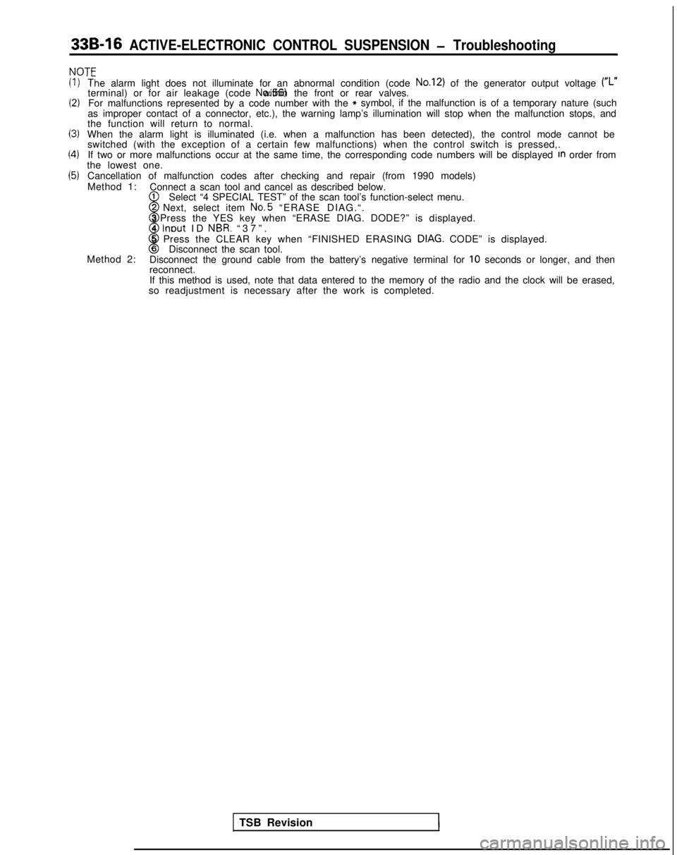
33B-16 ACTIVE-ELECTRONIC CONTROL SUSPENSION - Troubleshooting
NOT’=
(1)
(2)
13)
(4)
(5)
‘T‘he alarm light does not illuminate for an abnormal condition (code No.12) of the generator output voltage (#,.terminal) or for air leakage (code No.56) within the front or rear valves.
For malfunctions represented by a code number with the* symbol, if the malfunction is of a temporary nature (such
as improper contact of a connector, etc.), the warning lamp’s illumi\
nation will stop when the malfunction stops, and
the function will return to normal.
When the alarm light is illuminated (i.e. when a malfunction has been d\
etected), the control mode cannot be switched (with the exception of a certain few malfunctions) when the c\
ontrol switch is pressed,.
If two or more malfunctions occur at the same time, the corresponding co\
de numbers will be displayed
In order from
the lowest one.
Cancellation of malfunction codes after checking and repair (from 1990 \
models)
Method 1: Connect a scan tool and cancel as described below.
1
w
Select “4 SPECIAL TEST” of the scan tool’s function-select menu\
.2 Next, select item No.5
“ERASE DIAG.“.
3 Press the YES key when “ERASE DIAG. DODE?” is displayed.
4
lnout ID NBR. “37”
.
8
5 Press the CLEAR key when “FINISHED ERASING DIAG. CODE” is displayed.6Disconnect the scan tool.
Method 2: Disconnect the ground cable from the battery’s negative terminal for \
10 seconds or longer, and then
reconnect.
If this method is used, note that data entered to the memory of the radi\
o and the clock will be erased,
so readjustment is necessary after the work is completed.
TSB Revision
1
Page 1263 of 1273
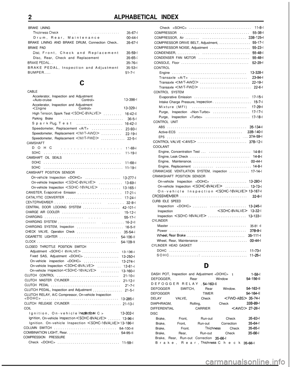
2ALPHABETICAL INDEX
BRAKE LINING ThicknessCheck
.., ..,............
Drum, Rear, Maintenanc
e
BRAKE LINING AND BRAKE DRUM, Connection Check..
BRAKE PAD
Drsc, Front, Check and Replacemen
t
Disc, Rear, Check and Replacement BRAKEPEDAL..
BRAKE PEDAL, Inspection and Adjustment
BUMPER..... 35-67-l
00-44-l
35-67-l
35-59-l
35-65-l
35-76-l
35-53-l
51-7-I
C
CABLEAccelerator, Inspection and Adjustment
Accelerator, Inspection and Adjustment
High
Tensron, Spark Test
.
16-42-11Parking Brake................................
.
36-5-l
Spark
Plug, Tes
t
........................
16-42-11Speedometer, Replacement ...............
.
23-93-l
Speedometer, Replacement
.
22-19-I
Speedometer, Replacement
.
22-5-l
CAMSHAFTDOH
C
...................
1 l-68-lSOHC.................................
.
11-19-I
CAMSHAFT OIL SEALS
DOHC
...................................
.
11-68-I
SOHC........................................
.
11-19-I
CAMSHAFT POSITION SENSOR
On-vehrcle Inspection
..................
.
13-277-l
On-vehicle Inspection
.
13-69-l
On-vehicle Inspection
.
13-165-I
CANISTER,
Evaporatjve Emission.................
.
17-21-l
CATALYTIC CONVERTER............................
.
17-24-l
CENTERMEMBER...................
.
....... 32-8-l
CENTRAL DOOR LOCKING SYSTEM..................
.
42-101-I
CHARGE AIR COOLER...............................
.
15-l
2-l
CHARGING..................
.
..... 55-17-I
CHARGING SYSTEM....................
.
...........
16-2-11CHARGING SYSTEM, Inspection.......................
.
16-5-11CHECK VALVE, Operation Check......................
.
35-54-l
CIGARETTE LIGHTER..........................
.
54-106-11
CLOCK........................................
.
54-109-11CLOSED THROTTLE POSITION SWITCHAdjustment
.................. 13-136-I
Frxed SAS, Adjustment
..................
.
13-250-I
On-vehicle inspection
On-vehicle Inspection
.
13-61-I
On-vehicle Inspection
. 13-160-I
CLUTCH CONTROL.................................
.
21-10-I
CLUTCH MASTER CYLINDER.........................
.
21-12-l
CLUTCH PEDAL.....................................
.
21-7-l
CLUTCH PEDAL, Inspection and Adjustment ................
21-5-1CLUTCH RELAY, A/C Compressor, On-vehicle Inspection
....................................... 13-285-l
CLUTCH RELEASE CYLINDER.........................
21-13-lCOIL
Ignition, On-vehicle
Inspectron
Ignition, On-vehicle
InspectIon
. 13-96-l
Ignition. On-vehicle Inspection
COLUMN SWITCH............................
.
54-100-11COMBINATION LIGHT, Rear.
.........................
.
54-95-11COMPRESSION PRESSURE
Check
...............................
.
1
i-59-1Check
..................................
11-8-l
COMPRESSOR...................................
.
55-38-l
COMPRESSOR, Air.......
.
........................ 338-125-I
COMPRESSOR DRIVE BELT, Adjustment, ................. 55-17-l
COMPRESSOR NOISE, Adjustment ...................... 55-23-l
CONDENSER, ............ .......................... 55-48-l
CONDENSER FAN MOTOR...........................
.
55-48-l
CONSOLE, Floor....................................
.
52-29-l
CONTROL
Engine
........................................
.
13-328-l
Transaxle ............................... 23-94-l
Transaxle
.
22-19-I
Transaxle
.
22-6-l
CONTROL SYSTEM
Evaporative Emission
.............................
.
17-15-l
Intake Charge Pressure, Inspection.
....................
15-7-lMixture (MFI
)
.............................. 17-29-l
Purge, Inspection
Purge, Inspection
CONTROL UNIT
ABS
........................................
.
35-134-l
Active-ECS ................................... 338-140-I
EPS.....................................
.
...37A-59-lCONTROL VALVE <4WS>..........................
.
378-12-I
COOLANT
Engine, Concentration Test ..........................
14-8-lEngine, Leak Check ................................
.
14-8-l
Engine, Maintenance. ............................ 00-44-I
Engine, Replacement ...........
................... 14-8-lCRANKCASE VENTILATION SYSTEM, inspection..........
.
17-14-l
CRANKSHAFT POSITION SENSOR
On-vehicle Inspection
..................
.
13-280-I
On-vehicle Inspection
.
13-73-l
On-vehicle Inspection
CROSSMEMBER....................................
.
32-8-l
CURB IDLE SPEED
Inspection
.......
.
.................... 13-245-l
Inspection
Inspection
.
13-133-l
CYLINDER
Master
.........................................
.
35-81 -IPower
.........................................
.
378-9-I
Wheel,RearBrake...............................
. 35-111-l
Wheel, Rear, Maintenance .......................... 00-44-I
CYLINDER HEAD GASKET
DOHC
.......................................
.
11-73-l
SOHC.................: ......................... 11-25-l
D
DASH POT, Inspection and Adjustment
1 l-58-lDEFOGGER, Rear Window 64-156-11
DEFOGGER RELA
Y
.54-163-11DEFOGGER SWITCH, Rear Window. 54-163-11
DEFOGGER TIMER 54-164-11
DELAY VALVE, Check
35-74-l
DIAPHRAGM, Rolling, Check 33B-89-l
DIFFERENTIAL CARRIER
DISC
Brake, Front, Run-out Check
35-63-l
Brake, Front, Run-out Correction 35-64-l
Brake, Front.
Thichness Check 35-65-l
Brake, Rear, Run-out Check 35-66-l
Brake, Rear, Run-out Correction 35-66-l
Brake, Rear,
Thichness Chec
k
35-66-l