1989 MITSUBISHI GALANT clock
[x] Cancel search: clockPage 108 of 1273
11-58ENGINE
4 Timing belt sideI
6EN0515
(3) lf
any abnormal noise IS not eliminated by racing. check the
lash adjuster
@ Stop the engine.
@ Set the engine so that cylinder
No. 1 IS positioned at
the top dead centre of the compression.
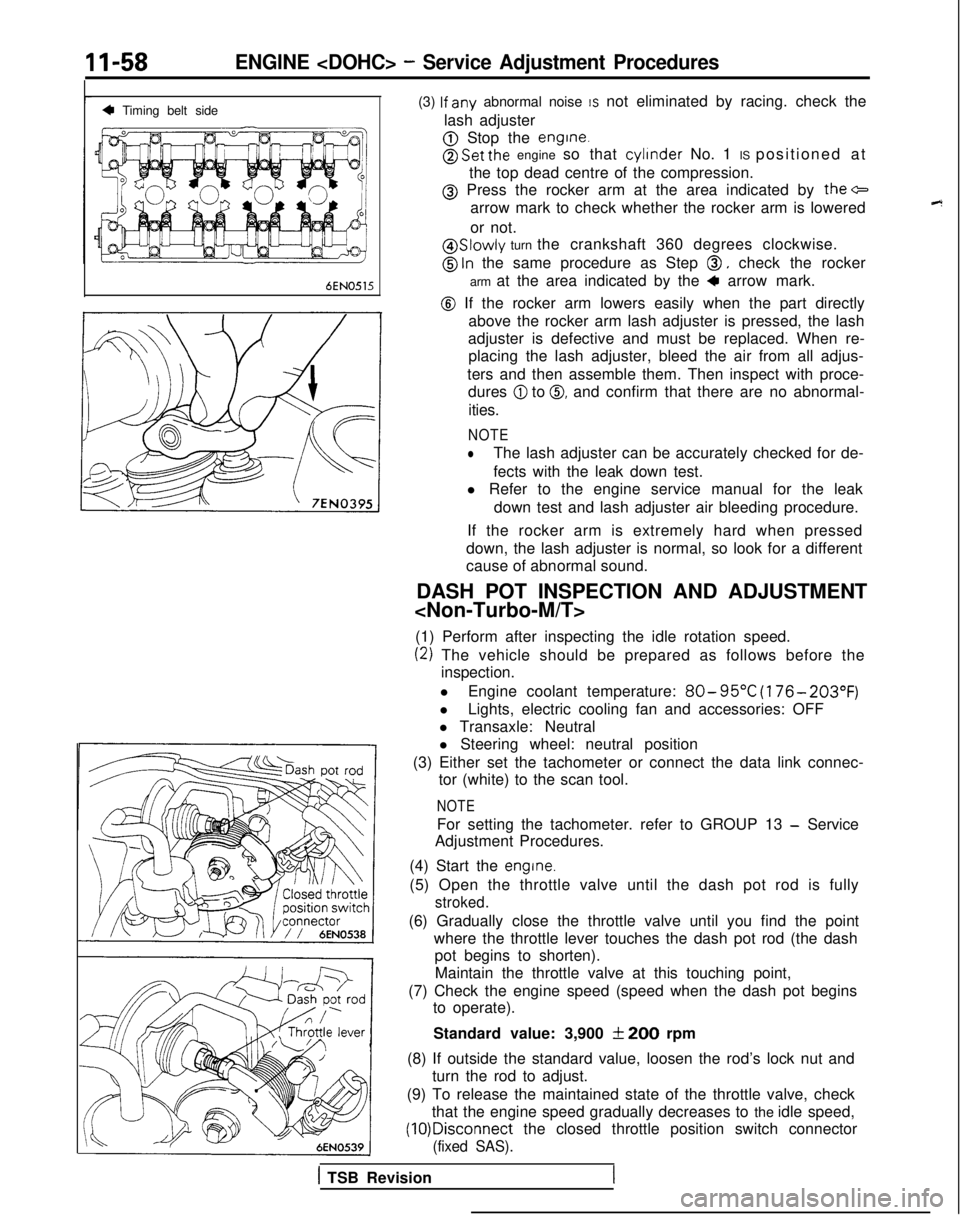
@ Press the rocker arm at the area indicated by the+
arrow mark to check whether the rocker arm is lowered
or not.
@ Slowly turn the crankshaft 360 degrees clockwise.
@ ln the same procedure as Step 0, check the rocker
arm at the area indicated by the
4 arrow mark.
@ If the rocker arm lowers easily when the part directly above the rocker arm lash adjuster is pressed, the lash
adjuster is defective and must be replaced. When re- placing the lash adjuster, bleed the air from all adjus-
ters and then assemble them. Then inspect with proce- dures
@I to 0, and confirm that there are no abnormal-
ities.
NOTE
lThe lash adjuster can be accurately checked for de-
fects with the leak down test.
l Refer to the engine service manual for the leak
down test and lash adjuster air bleeding procedure.
If the rocker arm is extremely hard when pressed
down, the lash adjuster is normal, so look for a different
cause of abnormal sound.
DASH POT INSPECTION AND ADJUSTMENT
(1) Perform after inspecting the idle rotation speed.
(2) The vehicle should be prepared as follows before the inspection.
l Engine coolant temperature:
80- 95°C
(176- 203°F)
lLights, electric cooling fan and accessories: OFF
l Transaxle: Neutral
l Steering wheel: neutral position
(3) Either set the tachometer or connect the data link connec- tor (white) to the scan tool.
NOTE
For setting the tachometer. refer to GROUP 13 - Service
Adjustment Procedures.
(4) Start the
engine.
(5) Open the throttle valve until the dash pot rod is fully
stroked.
(6) Gradually close the throttle valve until you find the point where the throttle lever touches the dash pot rod (the dashpot begins to shorten).
Maintain the throttle valve at this touching point,
(7) Check the engine speed (speed when the dash pot begins to operate).
Standard value: 3,900
f 200 rpm
(8) If outside the standard value, loosen the rod’s lock nut and turn the rod to adjust.
(9) To release the maintained state of the throttle valve, check that the engine speed gradually decreases to the idle speed, (10)Disconnect
the closed throttle position switch connector
(fixed SAS).
1 TSB Revision
Page 132 of 1273
II-82
SEALING POINTSENGINE
- Timing Belt
olaoo4~
0 1 A0583
Sealant: 3M ATD Part No.8660
or equivalent 04UOO27
1
Intake cam-IDowel
pinshaft sprocket
/~~*;~i~g~\Timing 1
- .,ICrankshatt-Oil pum
p
,
_sprockekI sproKer
OlAOOSl
1
SERVICE POINTS OF REMOVALMl 1KBDG
3. REMOVAL OF ENGINE MOUNT BRACKET
(1) With a wooden block placed against the oil pan part ofthe engine, jack up the vehicle.
Caution
Jack up gently, so as not to apply a load to the
various parts.
(2) Remove the engine mount bracket.
4. REMOVAL OF DRIVE BELT Before removing the drive belt, loosen the water pump
pulley mounting bolts.
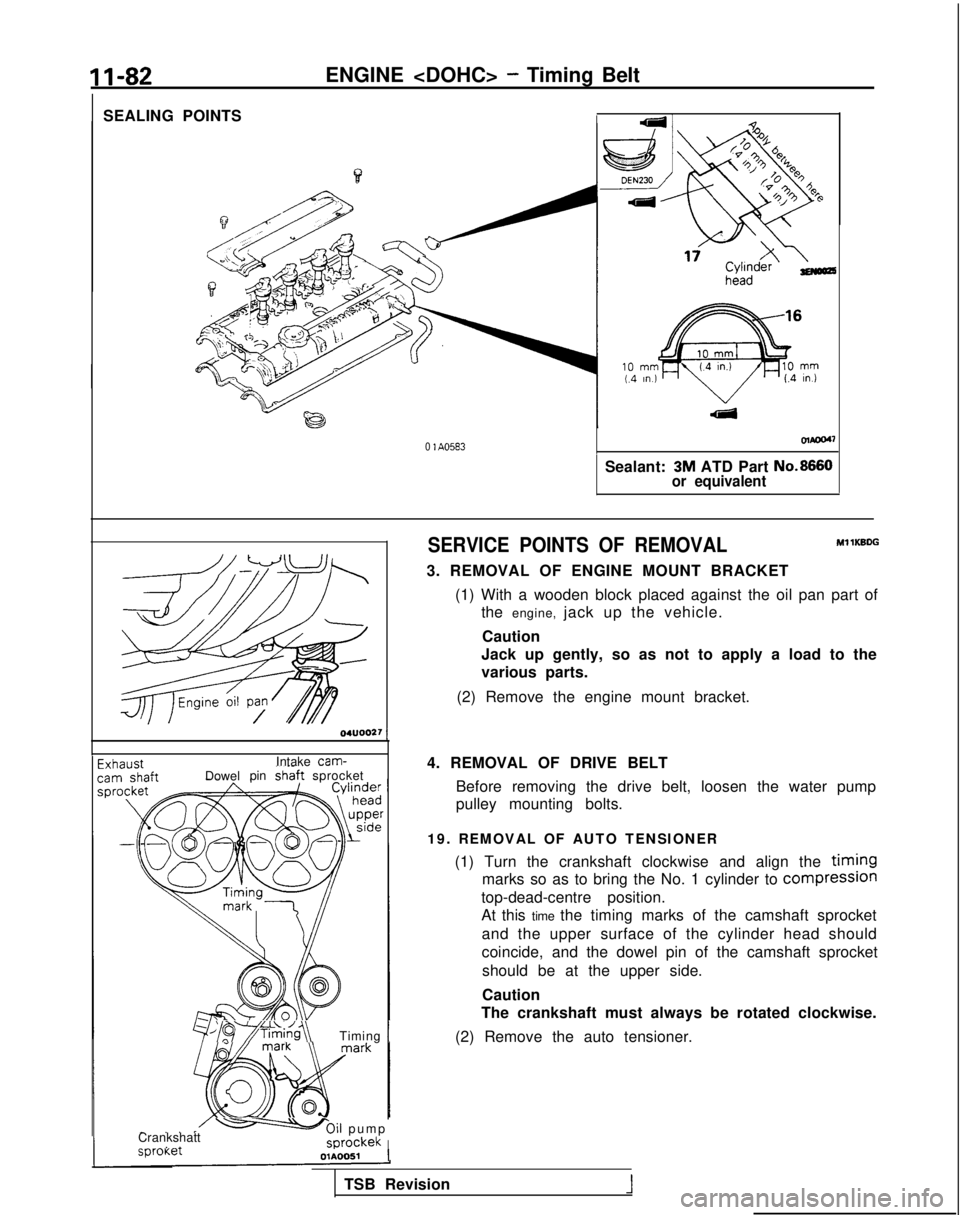
19. REMOVAL OF AUTO TENSIONER (1) Turn the crankshaft clockwise and align the
timing
marks so as to bring the No. 1 cylinder to compresslon
top-dead-centre position.
At this time the timing marks of the camshaft sprocket
and the upper surface of the cylinder head should
coincide, and the dowel pin of the camshaft sprocketshould be at the upper side.
Caution
The crankshaft must always be rotated clockwise.
(2) Remove the auto tensioner.
TSB Revision
1
Page 139 of 1273
ENGINE
Camshaft sprocket
Top surface of
cylinder head
/b*TJ,$
:-; /
e
\I’ \ii)’
Timing mark
6EN028L
--.-./Dowel pin
Timing mark
6EN0304
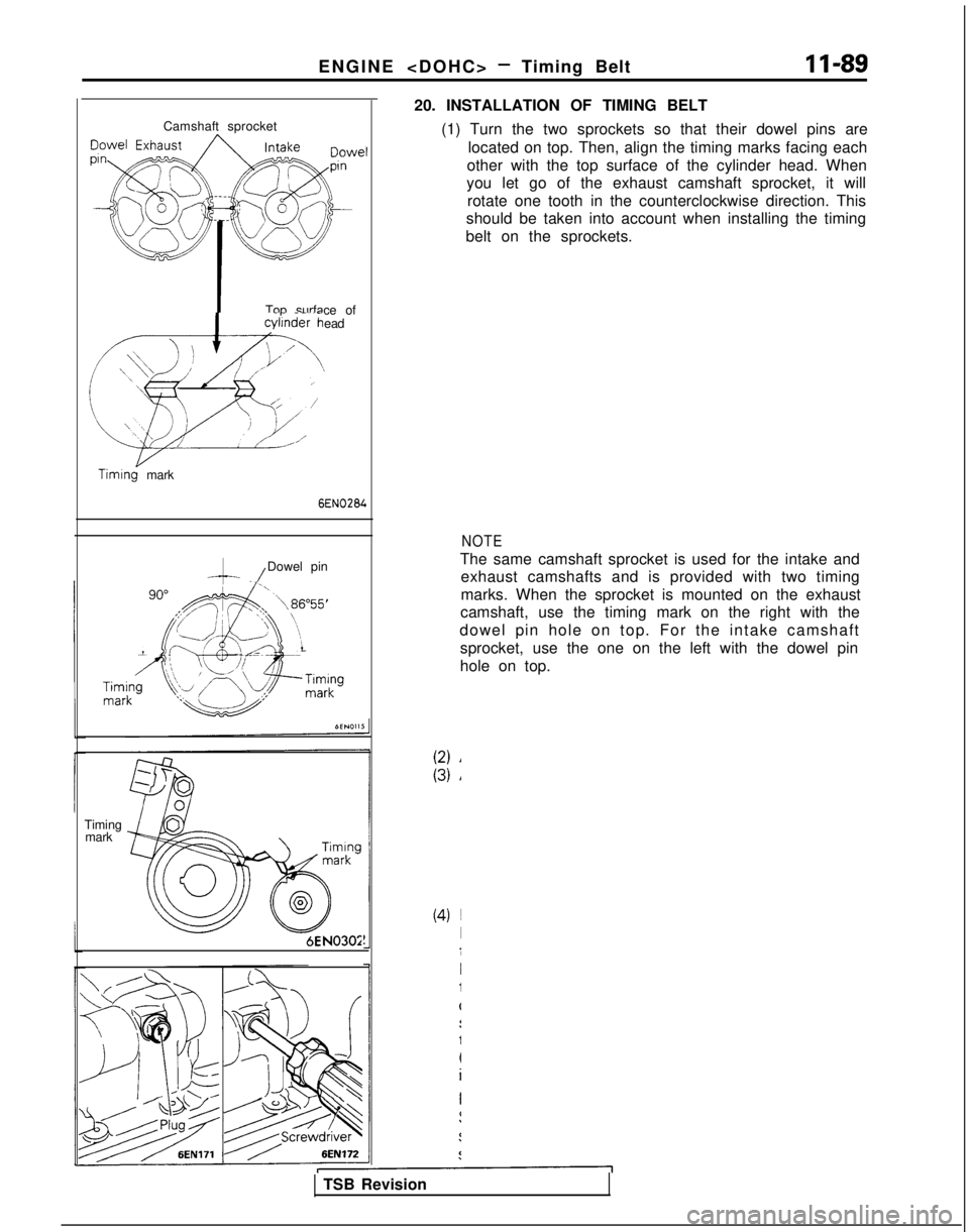
20. INSTALLATION OF TIMING BELT
(1) Turn the two sprockets so that their dowel pins arelocated on top. Then, align the timing marks facing each
other with the top surface of the cylinder head. When
you let go of the exhaust camshaft sprocket, it will
rotate one tooth in the counterclockwise direction. This
should be taken into account when installing the timing
belt on the sprockets.
NOTE
The same camshaft sprocket is used for the intake and exhaust camshafts and is provided with two timing
marks. When the sprocket is mounted on the exhaust
camshaft, use the timing mark on the right with the
dowel pin hole on top. For the intake camshaft sprocket, use the one on the left with the dowel pin
hole on top.
TSB Revision
Page 140 of 1273
II-90ENGINE
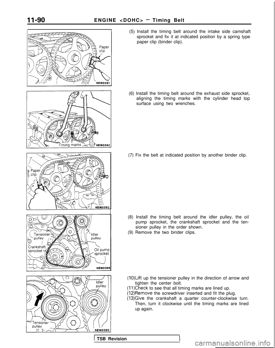
(5) Install the timing belt around the intake side camshaft sprocket and fix it at indicated position by a spring typepaper clip (binder clip).
(6) Install the timing belt around the exhaust side sprocket, aligning the timing marks with the cylinder head top
surface using two wrenches.
(7) Fix the belt at indicated position by another binder clip.
(8) Install the timing belt around the idler pulley, the oil pump sprocket, the crankshaft sprocket and the ten-
sioner pulley in the order shown.
(9) Remove the two binder clips.
(1O)Lift up the tensioner pulley in the direction of arrow and
tighten the center bolt.
(11)Check to see that all timing marks are lined up. (12)Remove
the screwdriver inserted and fit the plug.
(13)Give the crankshaft a quarter counter-clockwise turn.
Then, turn it clockwise until the timing marks are lined up again.
1 TSB Revision
Page 141 of 1273
ENGINE
J
Tensioner armTensioner arm
TSB Revision
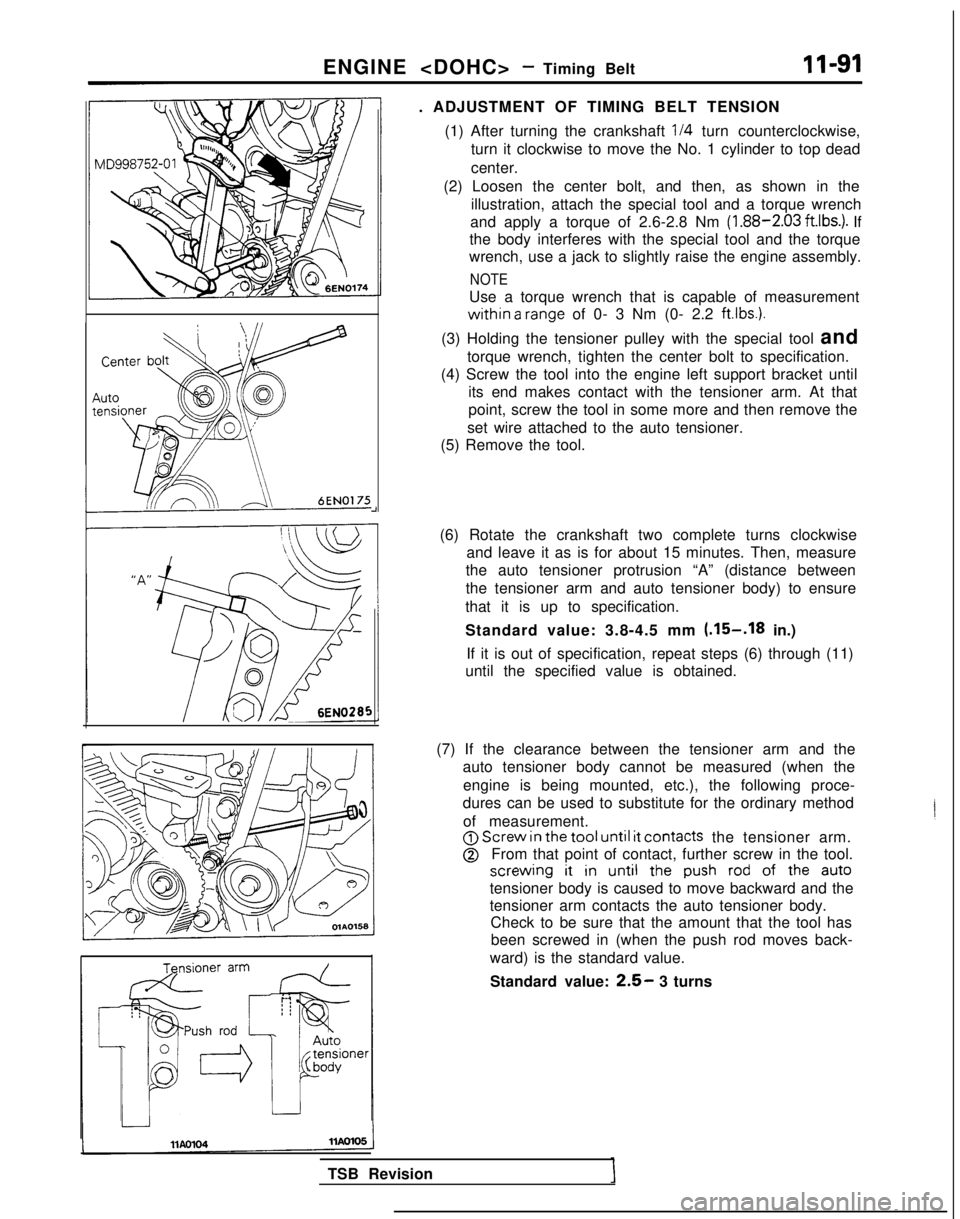
. ADJUSTMENT OF TIMING BELT TENSION
(1) After turning the crankshaft
l/4 turn counterclockwise,
turn it clockwise to move the No. 1 cylinder to top dead
center.
(2) Loosen the center bolt, and then, as shown in the illustration, attach the special tool and a torque wrench
and apply a torque of 2.6-2.8 Nm (1.88-2.03
ft.lbs.). If
the body interferes with the special tool and the torque
wrench, use a jack to slightly raise the engine assembly.
NOTE
Use a torque wrench that is capable of measurement
within a range of 0- 3 Nm (0- 2.2 ftlbs.).
(3) Holding the tensioner pulley with the special tool and torque wrench, tighten the center bolt to specification.
(4) Screw the tool into the engine left support bracket until its end makes contact with the tensioner arm. At that
point, screw the tool in some more and then remove the
set wire attached to the auto tensioner.
(5) Remove the tool.
(6) Rotate the crankshaft two complete turns clockwise and leave it as is for about 15 minutes. Then, measure
the auto tensioner protrusion “A” (distance between
the tensioner arm and auto tensioner body) to ensure
that it is up to specification.
Standard value: 3.8-4.5 mm
(.15-.I8 in.)
If it is out of specification, repeat steps (6) through (11)
until the specified value is obtained.
(7) If the clearance between the tensioner arm and the auto tensioner body cannot be measured (when the
engine is being mounted, etc.), the following proce-
dures can be used to substitute for the ordinary method
of measurement.
@j Screw in
the tool until it
contacts the tensioner arm.
@From that point of contact, further screw in the tool.
screwing it in
until the push
rod
of the auto
tensioner body is caused to move backward and the
tensioner arm contacts the auto tensioner body.
Check to be sure that the amount that the tool has
been screwed in (when the push rod moves back-
ward) is the standard value.
Standard value:
2.5- 3 turns
Page 179 of 1273
FUEL SYSTEM (SOHC-8 VALVE> -Service Adjustment Procedures 13-37
MO-L
6FU1405
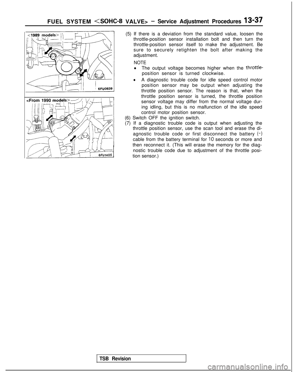
(5) If there is a deviation from the standard value, loosen the
throttle-position sensor installation bolt and then turn the
throttle-position sensor itself to make the adjustment. Be
sure to securely retighten the bolt after making the
adjustment.
NOTE
lThe output voltage becomes higher when the throttle-
position sensor is turned clockwise.
lA diagnostic trouble code for idle speed control motor position sensor may be output when adjusting the
throttle position sensor. The reason is that, when the
throttle position sensor is turned, the throttle position sensor voltage may differ from the normal voltage dur-
ing idling, but this is no malfunction of the idle speed
control motor position sensor.
(6) Switch OFF the ignition switch. (7) If a diagnostic trouble code is output when adjusting the throttle position sensor, use the scan tool and erase the di-
agnostic trouble code or first disconnect the battery (-)
cable from the battery terminal for IO
seconds or more and
then reconnect it. (This will erase the memory for the diag- nostic trouble code due to adjustment of the throttle posi-
tion sensor.)
TSB Revision
Page 279 of 1273
FUEL SYSTEM
I;gFixed SAS
Terminal @Terminal @(sensor output) (sensor ground) /
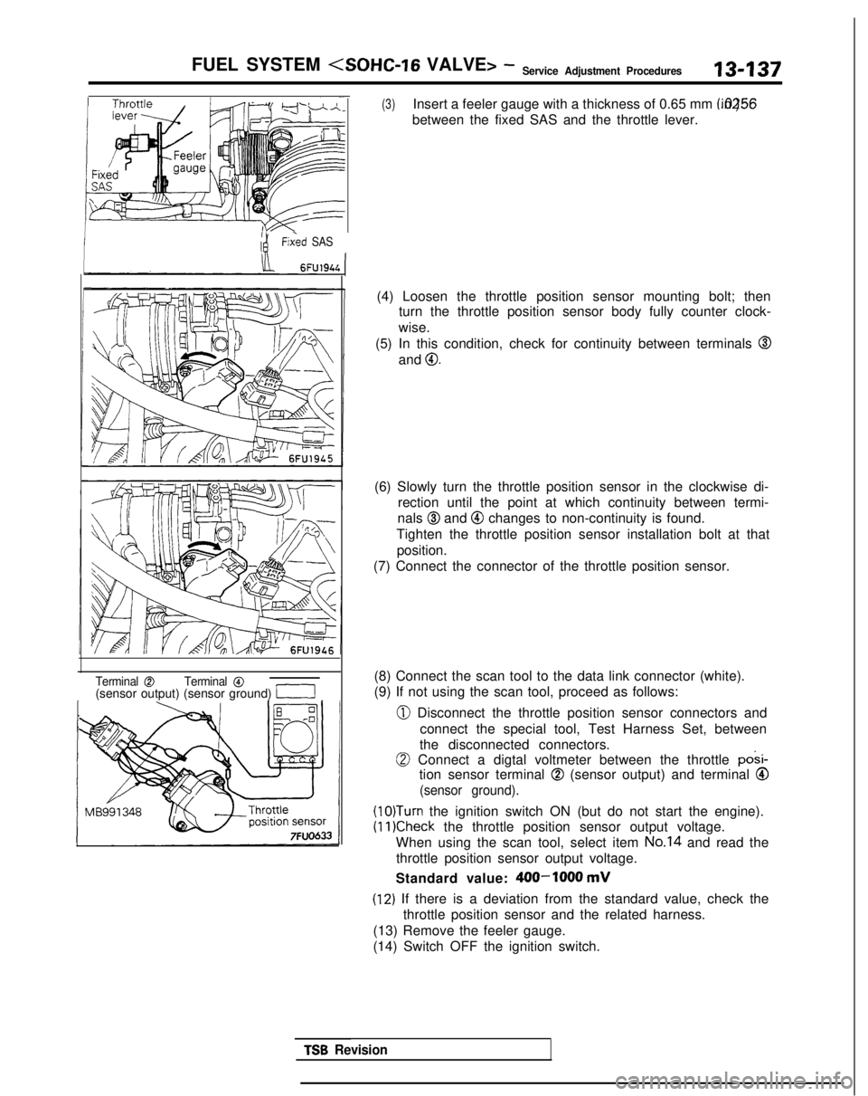
(3)Insert a feeler gauge with a thickness of 0.65 mm (.0256 in.)
between the fixed SAS and the throttle lever.
(4) Loosen the throttle position sensor mounting bolt; then turn the throttle position sensor body fully counter clock-
wise.
(5) In this condition, check for continuity between terminals
@
and 0.
(6) Slowly turn the throttle position sensor in the clockwise di- rection until the point at which continuity between termi-
nals
@I and @ changes to non-continuity is found.
Tighten the throttle position sensor installation bolt at that position.
(7) Connect the connector of the throttle position sensor.
(8) Connect the scan tool to the data link connector (white).
(9) If not using the scan tool, proceed as follows:
0 Disconnect the throttle position sensor connectors and connect the special tool, Test Harness Set, between
the disconnected connectors.
0 Connect a digtal voltmeter between the throttle posi-
tion sensor terminal
@ (sensor output) and terminal Q
(sensor ground).
(lO)Turn the ignition switch ON (but do not start the engine).
(11)Check the throttle position sensor output voltage.
When using the scan tool, select item
No.14 and read the
throttle position sensor output voltage.
Standard value:
400-1000 mV
(12) If there is a deviation from the standard value, check the throttle position sensor and the related harness.
(13) Remove the feeler gauge.
(14) Switch OFF the ignition switch.
TSB Revision
Page 280 of 1273
13-138
FUEL SYSTEM (SOHC-16 VALVE>- Service Adjustment Procedures
FIXED SAS ADJUSTMENT
M13FlDE
NOTE
I,The fixed SAS should not be moved unnecessarily; it has been precisely adjusted by the manufacturer.
2.If the adjustment for any reason is disturbed, readjust as
follows.
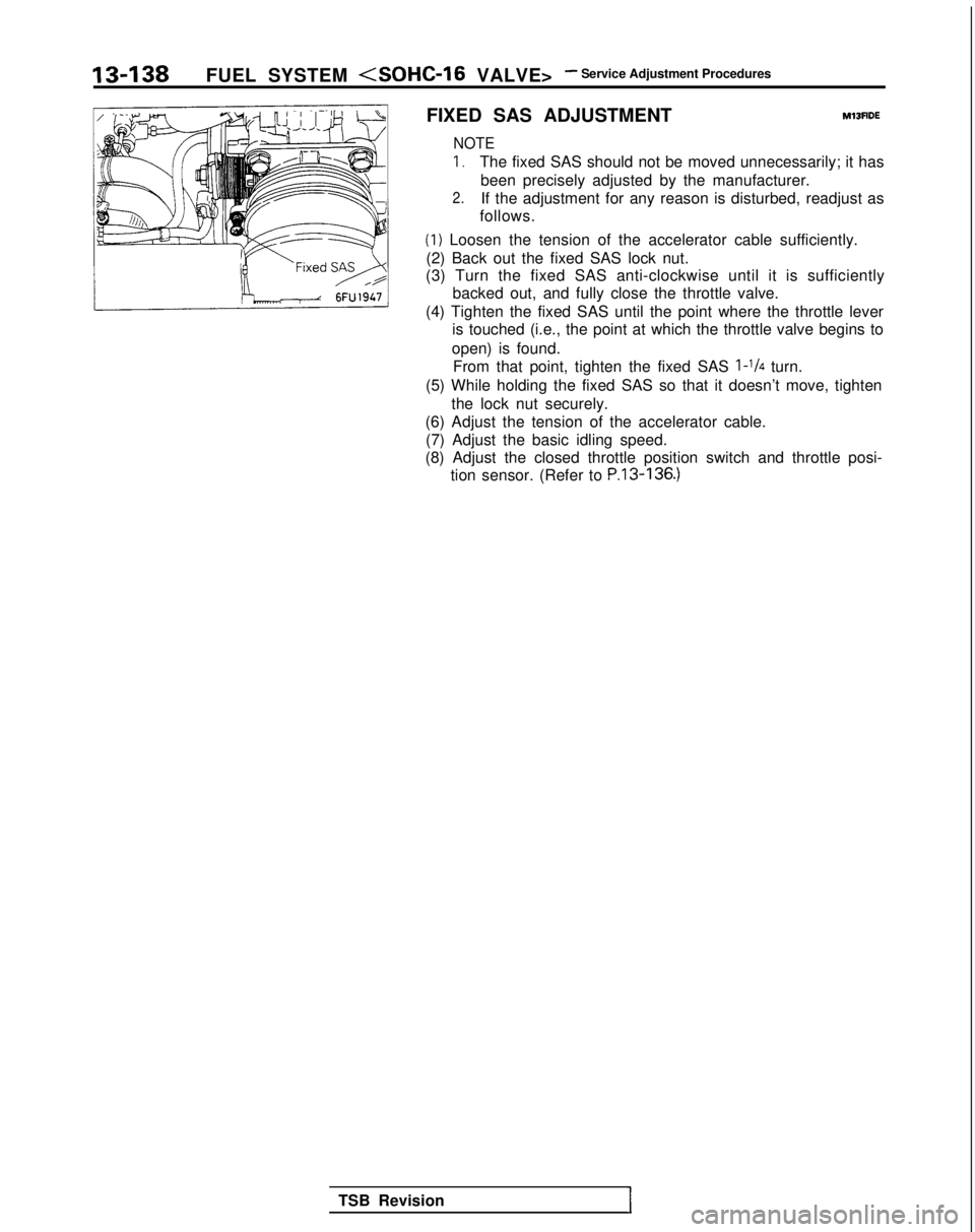
(1) Loosen the tension of the accelerator cable sufficiently.
(2) Back out the fixed SAS lock nut.
(3) Turn the fixed SAS anti-clockwise until it is sufficiently
backed out, and fully close the throttle valve.
(4) Tighten the fixed SAS until the point where the throttle lever is touched (i.e., the point at which the throttle valve begins to
open) is found. From that point, tighten the fixed SAS
l-1/4 turn.
(5) While holding the fixed SAS so that it doesn’t move, tighten the lock nut securely.
(6) Adjust the tension of the accelerator cable. (7) Adjust the basic idling speed.
(8) Adjust the closed throttle position switch and throttle posi- tion sensor. (Refer to
P.13-136.)
TSB RevisionI