1989 MITSUBISHI GALANT boot
[x] Cancel search: bootPage 3 of 1273
00-l
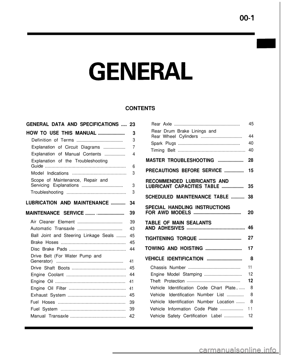
GENERAL
CONTENTS
GENERAL DATA AND SPECIFICATIONS.....23
HOWTOUSETHISMANUAL......................
3
Definition of Terms ......................................3
ExplanationofCircuitDiagrams..................7
Explanation of
ManualContents .................4
Explanation of the Troubleshooting
Guide .............................................................
6
Model
Indications .........................................3
Scope of Maintenance, Repair and
Servicing Explanations
..................................
3
Troubleshooting .............................................3
LUBRICATIONANDMAINTENANCE............
34
MAINTENANCE SERVICE............................... 39
AirCleanerElement
.....................................39
Automatic
Transaxle
.....................................43
Ball Joint and Steering Linkage Seals ........45
Brake Hoses................................................. 45
Disc Brake Pads ........................................... 44
Drive Belt (For Water Pump and
Generator) .......................................................
41
Drive
Shaft Boots .........................................45
Engine Coolant
............................................. 44
Engine Oil .....................................................
41
Engine Oil Filter ...........................................41
Exhaust System
............................................ 45
FuelHoses
...................................................39
Fuel System
.................................................39
Manual Transaxle ..........................................42
RearAxle......................................................45
Rear Drum Brake Linings and
RearWheel Cylinders
..................................44
Spark
Plugs...................................................40
Timing Belt...................................................40
MASTER
TROUBLESHOOTING.....................28
PRECAUTIONS
BEFORESERVICE................15
RECOMMENDED LUBRICANTS AND
LUBRICANT CAPACITIESTABLE..................35
SCHEDULED
MAINTENANCETABLE ...........38
SPECIAL HANDLING INSTRUCTIONS
FOR AWD MODELS
.......................................20
TABLE OF MAIN SEALANTS
AND
ADHESIVES ............................................46
TIGHTENING TORQUE
................................... 27
TOWING
ANDHOISTING ..............................17
VEHICLE
IDENTIFICATION .............................8
Chassis Number ...........................................
11
EngineModel
Stamping
...............................12
Theft Protection ............................................12
Vehicle Identification Code Chart Plate.......
8
Vehicle Identification Number List
..............8
Vehicle Identification Number Location .......
8
Vehicle Information
CodePlate...................1 1
Vehicle SafetyCertificationLabel................12
Page 40 of 1273
00-38GENERAL- Scheduled Maintenance Table
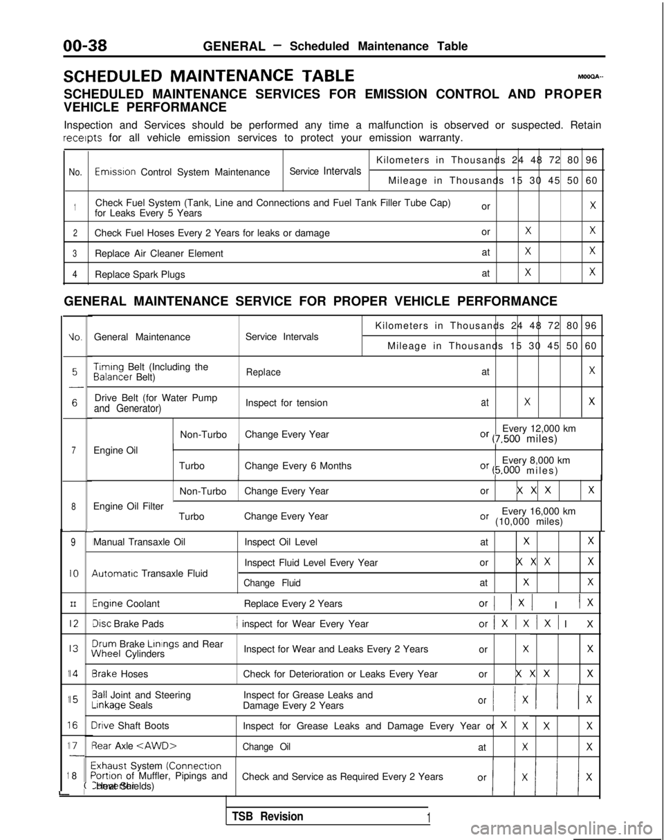
SCHEDULED MAINTENANCE
TABLEMOOOA-
SCHEDULED MAINTENANCE SERVICES FOR EMISSION CONTROL AND PROPER
VEHICLE PERFORMANCE
Inspection and Services should be performed any time a malfunction is ob\
served or suspected. Retain receipts
for all vehicle emission services to protect your emission warranty.
Kilometers in Thousands 24 48 72 80 96
No.Emwsron Control System MaintenanceService IntervalsMileage in Thousands 15 30 45 50 60
1Check Fuel System (Tank, Line and Connections and Fuel Tank Filler Tube\
Cap) orXfor Leaks Every 5 Years
2Check Fuel Hoses Every 2 Years for leaks or damage orXX
3Replace Air Cleaner ElementatXX
4Replace Spark PlugsatXX
GENERAL MAINTENANCE SERVICE FOR PROPER VEHICLE PERFORMANCE
L
1
1
1
1
1
i
IO.General Maintenance
Service Intervals
7Engine Oil
8
9
IO
III2
I3
14
15
I6
I71
8
L
I
I
I
I
I\
I
II
I
I
;(
Kilometers in Thousands 24 48 72 80 96
Mileage in Thousands 15 30 45 50 60 Timing
Belt (Including the Balancer
Belt)
ReplaceatX
Drive Belt (for Water Pump
Inspect for tensionatXXand Generator)
Non-TurboChange Every Year Every 12,000 kmOr (7,500 miles)
Turbo Change Every 6 Months Every 8,000 km
Or (5.000 miles
)
II
Non-Turbo
Change Every Year or X X XX
Every 16,000 kmOr (10,000 miles)
Engine Oil Filter
TurboChange Every Year
Manual Transaxle Oil 4utomatrc
Transaxle Fluid Inspect Oil Level
at
XX
Inspect Fluid Level Every Yearor X X XX
Change FluidatXX
Engine Coolant
Replace Every 2 YearsOrI 1x1 I IX
Disc Brake Pads1 inspect for Wear Every Yearor/XlXlXl I
X
3rum
Brake Linings
and Rear iNheel
Cylinders Inspect for Wear and Leaks Every 2 Years
or
XX
3rake HosesCheck for Deterioration or Leaks Every Year or X X XX
3all Joint and SteeringInspect for Grease Leaks and-inkage
Seals
Damage Every 2 Years
Or I/ XII x
Irive Shaft Boots Inspect for Grease Leaks and Damage Every Year or XXXX
3ear Axle
Exhaust System (Connectron>ortion of Muffler, Pipings and
Check and Service as Required Every 2 YearsConverter Heat Shields)
TSB Revision1
Page 47 of 1273
14KO24
OOA0186
GENERAL - Maintenance Service00-45
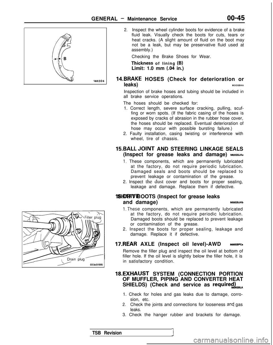
2.Inspect the wheel cylinder boots for evidence of a brake
fluid leak. Visually check the boots for cuts, tears or heat cracks. (A slight amount of fluid on the boot may
not be a leak, but may be preservative fluid used at
assembly.)
Checking the Brake Shoes for Wear. Thiclkness
of lining (B)
Limit: 1.0 mm
(.04 in.)
14.BRAKEI HOSES (Check for deterioration or
leaks)MOOSBHA
Inspection of brake hoses and tubing should be included in
all brake service operations.
The hoses should be checked for: 1. Correct length, severe surface cracking, pulling, scuf- fing or worn spots. (If the fabric casing of the hoses is
exposed by cracks of abrasion in the rubber hose cover,
the hoses should be replaced. Eventual deterioration of hose may occur with possible bursting failure.)
2. Faulty installation, casing twisting or interference with wheel, tire of chassis.
15.BALL ,IOINT AND STEERING LINKAGE SEALS
(Inspect for grease leaks and damage)
MOOSBJAa
I, These components, which are permanently lubricated at the factory, do not require periodic lubrication.Damaged seals and boots should be replaced to
prevent leakage or contamination of the grease.
2. Inspect the dust cover and boots for proper sealing, leakage and damage. Replace them if defective. 16.DRIVE SHAFT BOOTS (Inspect for grease leaks
and damage) MOOSWAb
1. The.se components, which are permanently lubricated
at the factory, do not require periodic lubrication.
Damaged boots should be replaced to prevent leakage
or contamination of the grease.
2. Inspect the boots for proper sealing, leakage and damage. Replace it if defective.
17.REAR AXLE (Inspect oil level)-AWD MOOSBPQ
Remove the filler plug and inspect the oil level at bottom of
filler hole. If the oil level is slightly below the filler hole, it is
in satisfactory condition. 18.EXHAIJST
SYSTEM (CONNECTION PORTION
OF MUFFLER, PIPING AND CONVERTER HEAT
SHIELDS) (Check and service as
require$LsBU
1. Check for holes and gas leaks due to damage, corro- sion, etc.
2.Check the joints and connections for looseness and gas
leaks.
3. Check the hanger rubber and brackets for damage.
TSB Revision1
Page 662 of 1273
21-12CLUTCH - Clutch Master Cylinder
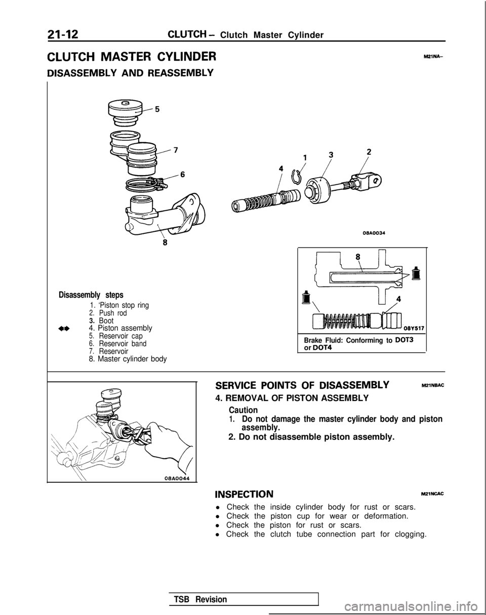
CLUTCH MASTER CYLINDER
DISASSEMBLY AND REASSEMBLY
MZlNA-
Disassembly steps
1. ‘Piston stop ring2.Push rod3.Boot
*I)4. Piston assembly5.Reservoircap6.Reservoirband7.Reservoir8. Master cylinder body
08AOO34
Brake Fluid: Conforming to DOT3or DOT4
SERVICE POINTS OF DISASSEMBLYMZlNBAC
4. REMOVAL OF PISTON ASSEMBLY
Caution
1.Do not damage the master cylinder body and piston
assembly.
2. Do not disassemble piston assembly.
\\08AOOi4
INSPECTIONM21NcAc
l Check the inside cylinder body for rust or scars.
l Check the piston cup for wear or deformation.
l Check the piston for rust or scars.
l Check the clutch tube connection part for clogging.
TSB Revision
Page 663 of 1273
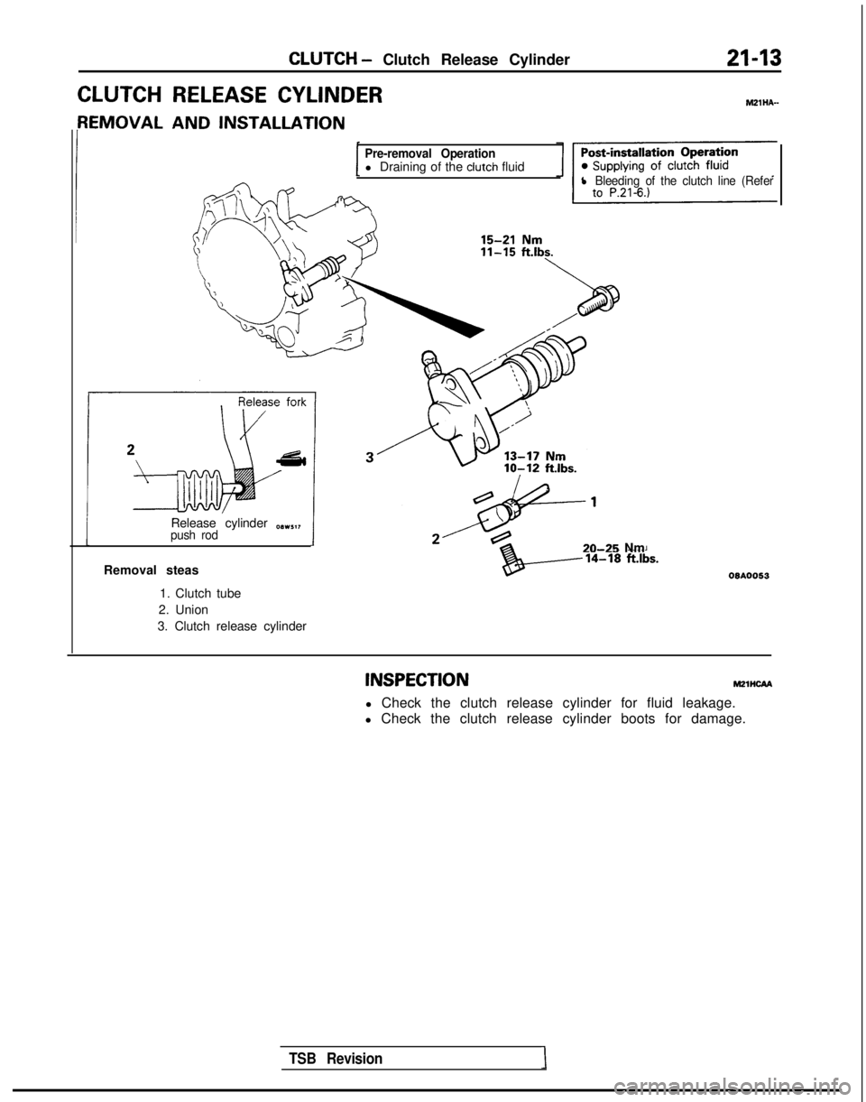
CLUTCH - Clutch Release Cylinder
CLUTCH RELEASE CYLINDER
{EMOVAL AND INSTALLATION
Pre-removal Operationl Draining of the clutch fluidl Bleeding of the clutch line (Refer
Release cylinder O(Ivl,,push rod
TSB Revision1
20-25 Nm
Removal steas
1. Clutch tube
2. Union
3. Clutch release cylinder
INSPECTIONm21ncAA
l Check the clutch release cylinder for fluid leakage.
l Check the clutch release cylinder boots for damage.
Page 670 of 1273
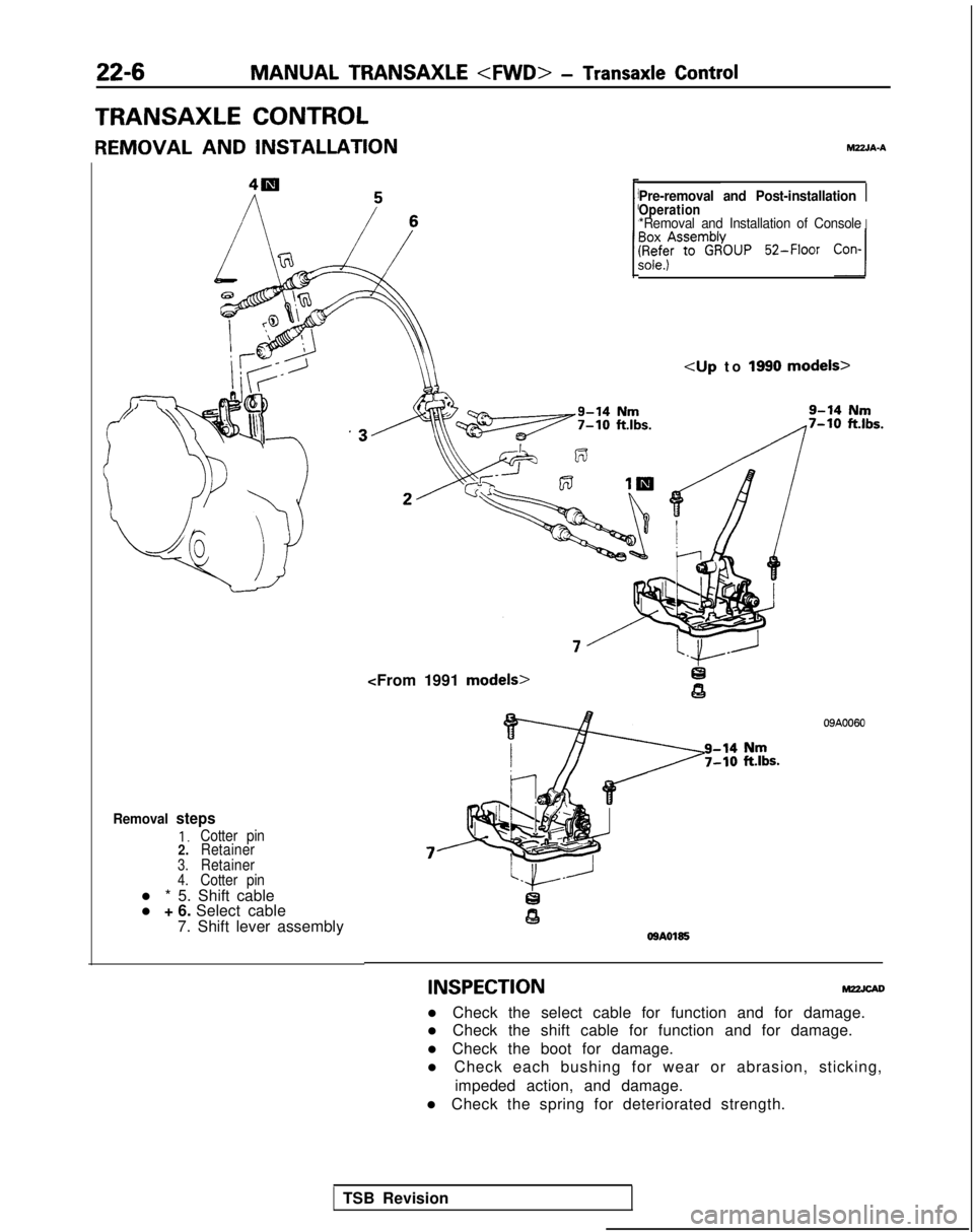
22-6MANUAL TRANSAXLE
- Transaxle Control
TRANSAXLE CONTROL
REMOVAL AND INSTALLATION hl22JA-A
Removal steps
1.Cotter pin
2. Retainer
3.Retainer4.Cotter pinl * 5. Shift cable
l + 6. Select cable
7. Shift lever assembly
Pre-removal and Post-installation 1Operation*Removal and Installation of ConsoleI
~$%!m$$NP Z-Floor
Con-l
9-14 Nm7-10 ftlbs.
09A0060
OSAO185
INSPECTION
l Check the select cable for function and for damage.
l Check the shift cable for function and for damage.
l Check the boot for damage.
l Check each bushing for wear or abrasion, sticking,
impeded action, and damage.
l Check the spring for deteriorated strength.
TSB Revision
Page 818 of 1273
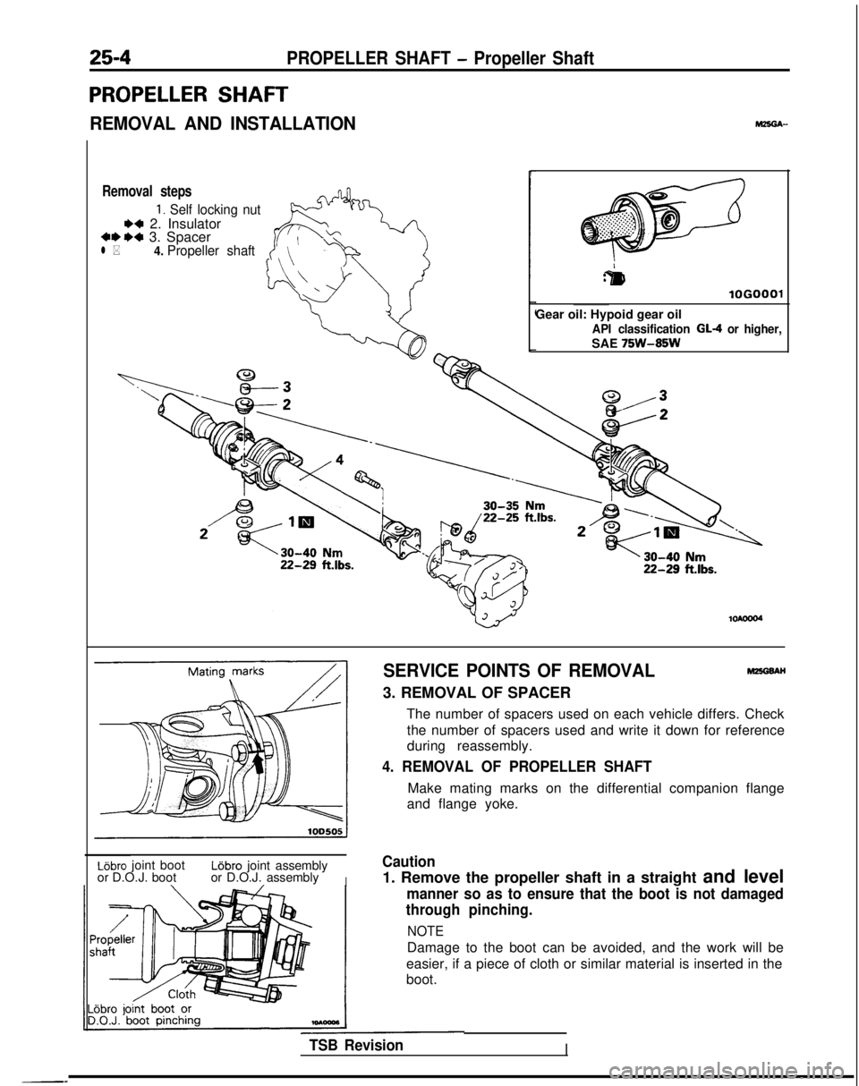
25-4PROPELLER SHAFT - Propeller Shaft
PROPELLER SHAFT
REMOVAL AND INSTALLATION
Removal steps
1. Self locking nut
** 2. Insulator***a 3. Spacerl *4.
Propeller shaft
r
:&I
lOGO
Gear oil: Hypoid gear oil
API classification GL-4 or higher,
SAE 75W-85W
SERVICE POINTS OF REMOVALMEGBAH
3. REMOVAL OF SPACER
The number of spacers used on each vehicle differs. Checkthe number of spacers used and write it down for reference
during reassembly.
4. REMOVAL OF PROPELLER SHAFT
Make mating marks on the differential companion flange
and flange yoke.
Lijbro joint bootL6bro joint assembly
or D.O.J. boot or D.O.J. assembly
I
Caution
1. Remove the propeller shaft in a straight and level
manner so as to ensure that the boot is not damaged
through pinching.
NOTE
Damage to the boot can be avoided, and the work will be
easier, if a piece of cloth or similar material is inserted in the
boot.
TSB RevisionI
Page 820 of 1273
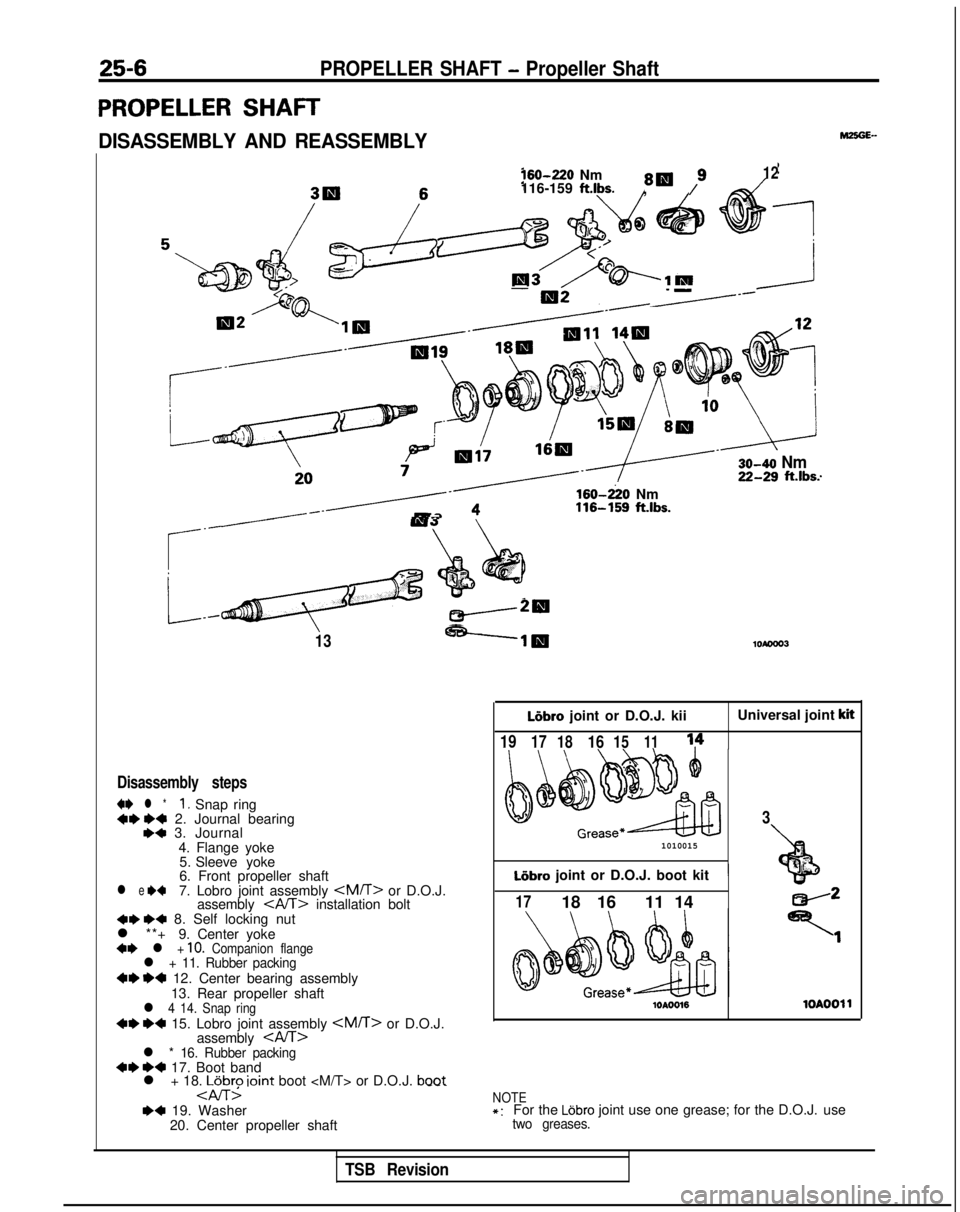
25-6PROPELLER SHAFT - Propeller Shaft
PROPELLER SHAFT
DISASSEMBLY AND REASSEMBLY160-220
Nm
8W /912116-159 ft.lbs.,
-
-I=------ 30-40
NmZG?~ ft.lbs.
/------d3
rQ”‘ ;+’
4s
.
G
*I4 :
_cw20
13-----lig
Disassembly steps
4I)
l *I, Snap ring+* I)+ 2. Journal bearing,a 3. Journal
4. Flange yoke5. Sleeve yoke
6. Front propeller shaft
l e +47. Lobro joint assembly
assembly
l **+ 9. Center yoke
+* l + 10. Companion flangel + 11. Rubber packing~~ ~~ 12. Center bearing assembly
13. Rear propeller shaft
l 4 14. Snap ring~~ ~~ 15. Lobro joint assembly
assembly
l + 18. LGbro ioint boot
--. 160-220
Nm 116-159
ft.lbs. LIbro
joint or D.O.J. kii Universal joint
kit
1917
18161511
1010015
Liibro joint or D.O.J. boot kit1
3
+bf ”
1718 16 11 14
lOAOO161OAOOll
NOTE*:For the Ldbro joint use one grease; for the D.O.J. usetwo greases.
TSB Revision