Page 859 of 1273

FRONT AXLE - Drive Shaft
26-2
9
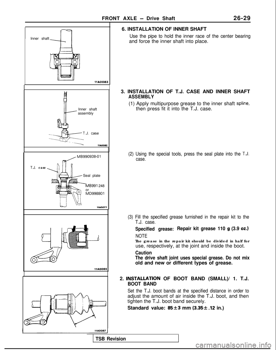
Inner shaft
~
llA0083
Inner shaft
assembly
---.
T.J.case MB990938-01
Seal plate
-MB991 248
or MD998801
-...A
llAOO05
IHA0087 1
6. INSTALLATION OF INNER SHAFT
Use the pipe to hold the inner race of the center bearing
and force the inner shaft into place.
3. INSTALLATION OF T.J. CASE AND INNER SHAFT
ASSEMBLY
(1) Apply multipurpose grease to the inner shaft spline,
then press fit it into the T.J. case.
(2) Using the special tools, press the seal plate into the T.J.
case.
(3) Fill the specified grease furnished in the repair kit to the T.J. case.
Specified grease:Repair kit grease 110 g (3.9 oz.)
NOTE
The grease in the repair kit should be divided in half foruse, respectively, at the joint and inside the boot.
Caution
The drive shaft joint uses special grease. Do not mix
old and new or different types of grease.
2.
INSTALLATlON OF BOOT BAND (SMALL)/ 1. T.J.
BOOT BAND
Set the T.J. boot bands at the specified distance in order to
adjust the amount of air inside the T.J. boot, and then
tighten the T.J. boot band securely.
Standard value:
85+3 mm (3.35-1- .12 in.)
TSB Revision
Page 870 of 1273

27-10REAR AXLE - Specifications
REAR AXLE
SPECIFICATIONS
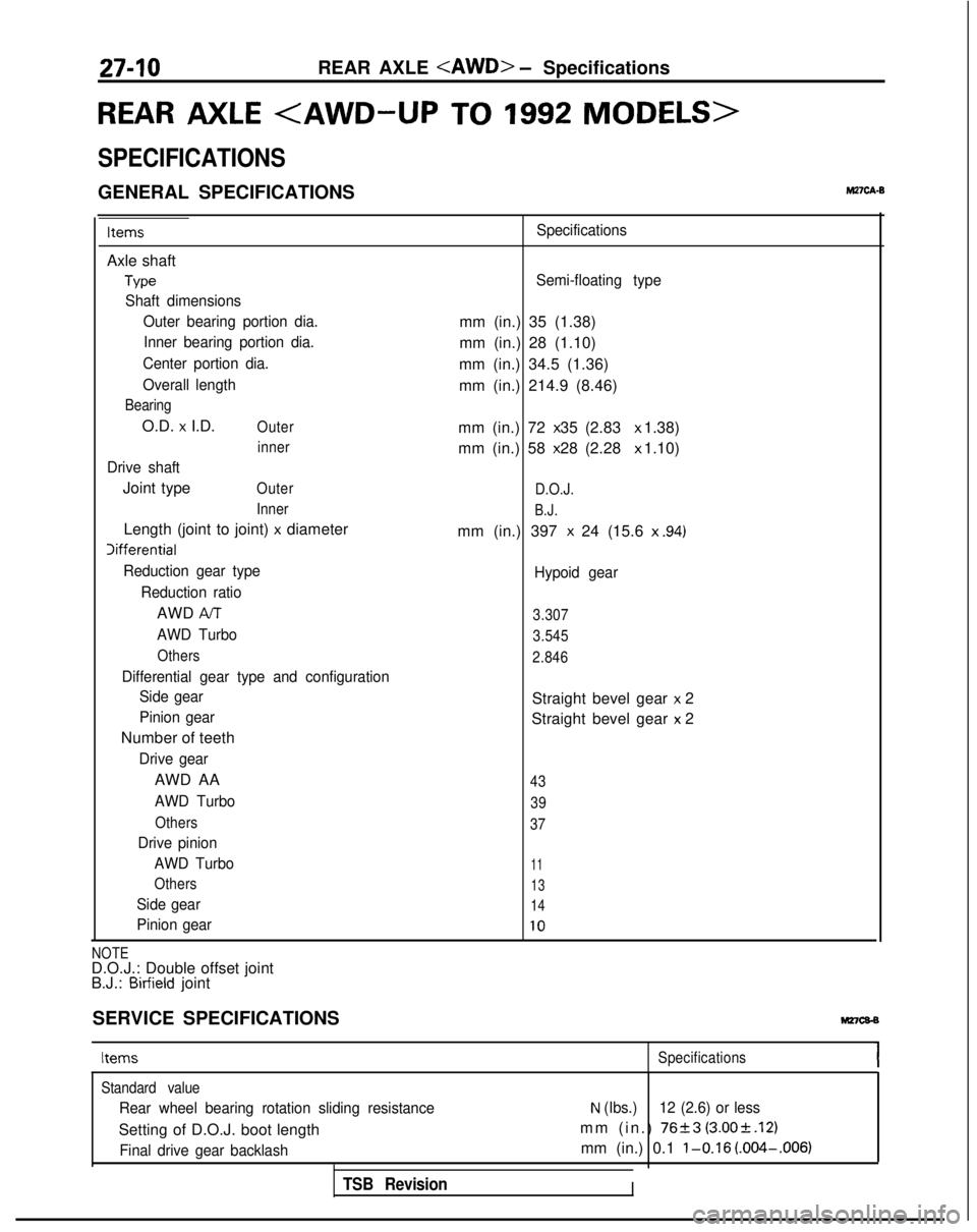
GENERAL SPECIFICATIONSM27cA.B
Items
Axle shaft
Type
Shaft dimensionsOuter bearing portion dia.Inner bearing portion dia.
Center portion dia.
Overall length
Bearing
O.D. x I.D.Outer inner
Drive shaft
Joint typeOuter
Inner
Length (joint to joint) x diameter Iifferential
Reduction gear type
Reduction ratio
AWD AIT
AWD Turbo
Others
Differential gear type and configurationSide gear
Pinion gear
Number of teeth
Drive gear
AWD AA
AWD Turbo
Others
Drive pinion
AWD Turbo
Others
Side gear
Pinion gear Specifications
Semi-floating type
mm (in.) 35 (1.38)
mm (in.) 28 (1.10)
mm (in.) 34.5 (1.36)
mm (in.) 214.9 (8.46)
mm (in.) 72 x 35 (2.83 x 1.38)
mm (in.) 58 x 28 (2.28 x 1.10)
D.O.J.
B.J.
mm (in.) 397 x 24 (15.6
x .94)
Hypoid gear
3.307
3.545
2.846
Straight bevel gear x 2
Straight bevel gear
x 2
43
39
37
11
13
14
10
NOTED.O.J.: Double offset joint
B.J.: Birfield joint
SERVICE SPECIFICATIONS
Mz7cs-s
Items Specifications
Standard value
Rear wheel bearing rotation sliding resistance
Setting of D.O.J. boot length
Final drive gear backlash
TSB Revision
N (Ibs.) 12 (2.6) or less
mm (in.) 7623 (3.00rt.12)
mm (in.) 0.1 l-0.16 (.004-.006)
I
Page 871 of 1273

REAR AXLE - SDecifications27-11
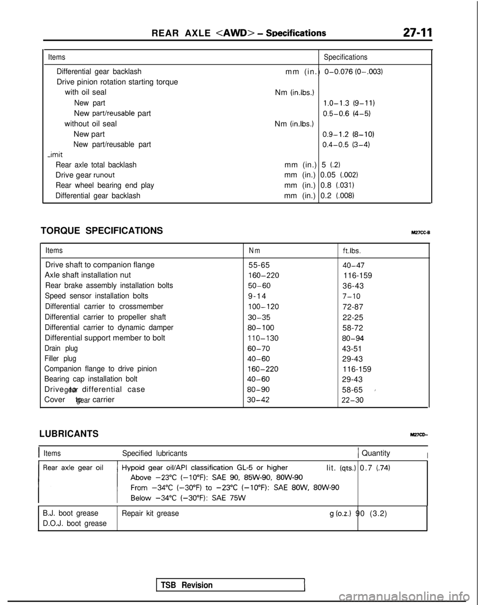
Items
Differential gear backlash
Drive pinion rotation starting torque
with oil seal
New part
New part/reusable part
without oil seal New part
New part/reusable part -imit
Rear axle total backlash
Drive gear runout
Rear wheel bearing end play
Differential gear backlash
Specifications
mm (in.) O-0.076 (O-.003)
Nm (in.lbs.) 1.0-1.3
(9-11)
0.5-0.6
(4-5)
Nm
(in.lbs.1 0.9-1.2
(8-10)
0.4-0.5
(3-4)
mm (in.) 5
(2)
mm (in.) 0.05 (.002)
mm (in.) 0.8 (.031)
mm (in.) 0.2 (008)
TORQUE SPECIFICATIONSM27cc-B
ItemsNmft.lbs.
Drive shaft to companion flange 55-6540-47
Axle shaft installation nut 160-220
116-159
Rear brake assembly installation bolts50-6036-43
Speed sensor installation bolts9-1
4
7-10
Differential carrier to crossmember
100-120
72-87
Differential carrier to propeller shaft30-3522-25
Differential carrier to dynamic damper80- 10058-72
Differential support member to bolt 110-130
80-94
Drain plug60-7043-51
Filler plug40-6029-43
Companion flange to drive pinion
160-220
116-159
Bearing cap installation bolt40-6029-43
Drive to differential case
gear80-9058-651
Cover to carriergear30-4222-30
TSB Revision
LUBRICANTS
IItemsSpecified lubricants1 QuantityI
lit. (qts.) 0.7 (74)
B.J. boot grease Repair kit grease
g (oz.) 90 (3.2)
D.O.J. boot grease
Page 880 of 1273
27-20REAR AXLE - Axle Shaft/Drive Shaft
DRIVE SHAFT
PARTS DISTINCTION
9. INSTALLATION OF REAR ROTOR
A.B.S.>
Press fit the rear rot,or to the axle shaft with the rear rotor
groove surface toward the axle shaft flange.
5. INSTALLATION OF SELF LOCKING NUT
With the special tool, secure the axle shaft and tighten the companion flange self locking nut.
M27JA-
Boots and boot bands can be distinguished by the
indicated part numbers shown below.
TSB Revision
Part shapesidentificationlocation
D.O.J. bootband
Identification
location
D.O.J. boot
Identification B.J. boot
B.J. boot band
Identification
Identification
location
llAO356 ran
laenrirrcarlon 110.17-131 #BJ82) 20-83I 17-169#BJ82 ) 20-110
Page 881 of 1273
REAR AXLE - Drive Shaft27-21
REMOVAL AND INSTALLATION
Removal steps
1.Bolt4,l +2.Drive shaft3.
Circlip
l 44.Oil seal
llAO32f
llAO324
SERVICE POINTS OF REMOVALM27JBAo
2. REMOVAL OF DRIVE SHAFT
Using a tire lever, etc. remove the drive shaft from the
differential carrier.
INSPECTIONM27JHAA
l Check the drive shaft boots for damage or deterioration.
lCheck the ball joints (B.J. and D.O.J.) for excessive play or
check operation. 0 Check the drive shaft spline for wear or damage.
SERVICE POINTS OF INSTALLATIONM27JCAF
4. INSTALLATlON OF OIL SEAL
If the oil seal is to be replaced because of damage, drive it
in by using the special tool.
2. INSTALLATION OF DRIVE SHAFT
Caution
Be cautious to ensure that the differential carrier oil seal is not damaged by the drive shaft spline.
TSB Revision
Page 882 of 1273
27-22REAR AXLE - Drive Shaft
DISASSEMBLY AND REASSEMBLYM27JD-
c
I -“&” -
YllA0075
5
1 lAOO69llAOO571 lAoo66
II
D.O.J. kitB.J. boot repair kit
D.O.J. boot repair kit
Disassembly steps 1. Circlip
2. Boot band
(B)3. Boot band (C)an.4. Lrrcnp
5. D.O.J. outer race
**6. Snap ring
**7. D.O.J. inner race, cage and ball assembly
8. Balls
::9.D.O.J. inner race
l *10. D.O.J. cage11.D.O.J. boot
12. Boot band (A)13. Boot band (C)*I)14. B.J. boot15.Dust cover
16. Drive shaft and B.J.
l 4 12. Boot band (A)
Reassembly steps
~~ 13. Boot band (C)l + 3. Boot band(C)l a 2. Boot band (B)*4’ 11. D.O.J. boot 16. Drive shaft and B.J.l +
15. Dust cover
7. D.O.J. inner race, cage and ball assembly
10. D.O.J. cage
9. D.O.J. inner race
l 4 14. B.J. boot
8. Balls
6. Snap ring
I)+ 5. D.O.J. outer race
4. Circlip
1.
Circlip
TSB Revision1
Page 883 of 1273
REAR AXLE - Drive Shaft27-23
LUBRICATION POINTS
llWI6#
Grease: Repair kit grease
TSB Revision
Grease: Repair kit grease 90 g (3.20 oz.)
CautionThe orease in the repair kit should be
divided in half for use, respectively, at
the joint andinA soecial tvoe ofide the boot.orease is used on thejoint. Be caitious ti ensure that no other
grease is allowd to come in contact with
the joint.
\ -
\llVlO6llvlos
Grease: Repair kit grease 90 g (3.20 oz.)
CautionThe grease in the repair kit should be
divided in half for use, respectively, at
the joint and inside the boot.
A special type of grease is used on thejoint. Be cautious to ensure that no othergrease is allowed to come in contact
with the joint.
Page 884 of 1273

27-24REAR AXLE - Drive Shaft
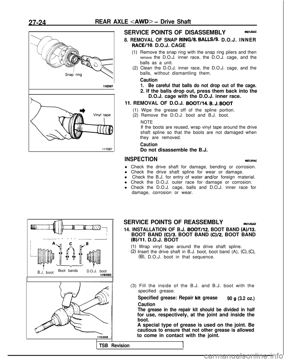
WE507llYG97
7___-- -- --
-
-.I
AC
~~~~~
B
”/
B.J: boot
Boot bands
D.O.J. bootVW592
SERVICE POINTS OF DISASSEMBLYMZ7JEAC
8. REMOVAL OF SNAP RING/8. BALLS/S. D.O.J. INNER RACE/lo.
D.O.J. CAGE (I
)Remove the snap ring with the snap ring pliers and then
remove the D.O.J. inner race, the D.O.J. cage, and the
balls as a unit.
(2) Clean the D.O.J. inner race, the D.O.J. cage, and the balls, without dismantling them.
Caution
1.Be careful that balls do not drop out of the cage.
2. If the balls drop out, press them back into the D.O.J. cage with the D.O.J. inner race.
11. REMOVAL OF D.O.J. BOOT/14. B. J. BOOT
(1) Wipe the grease off of the spline portion.
(2) Remove the D.O.J. boot and B.J. boot.
NOTE
If the boots are reused, wrap vinyl tape around the drive
shaft spline so that the boots are not damaged when
they are removed.
Caution
Do not disassemble the B.J.
INSPECTIONMZ7JFAC
l Check the drive shaft for damage, bending or corrosion.
l Check the drive shaft spline for wear or damage.
l Check the B.J. for entry of water and/or
foreign material.
l Check the D.O.J. outer race for damage or corrosion.
l Check the D.O.J. cage, balls and D.O.J. inner race for damage, corrosion or wear.
SERVICE POINTS OF REASSEMBLYMnJoAD
14. INSTALLATION OF B.J. BOOTI12. BOOT BAND (A)/13.
BOOT BAND (C)/3. BOOT BAND (C)/2. BOOT BAND
(B)/ll. D.O.J. BOOT
(I) Wrap vinyl tape around the drive shaft spline.
(2) Insert the drive shaft in B.J. boot, boot band (A), (C), (C),
(B), D.O.J. boot in that sequence.
(3) Fill the inside of the B.J. and B.J. boot with the specified grease.
Specified grease: Repair kit grease
Caution90 g (3.2 oz.)
The grease in the repair kit should be divided in half
for use, respectively, at the joint and inside the
boot.
A special type of grease is used on the joint. Be
cautious to ensure that not other grease is allowed
to come in contact with the joint.
TSB Revision1