1989 MITSUBISHI GALANT boot
[x] Cancel search: bootPage 1221 of 1273
35-100SERVICE BRAKES - Front Disc Brake
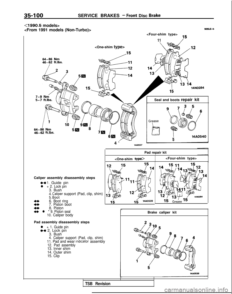
<1990.5 models>
11 M35LE-b
14N0284
I
.
64-88 Nmft Iha~5a’ P7El- I SW
Caliper assembly disassembly steps
~~ 1. Guide pinl + 2. Lock pin3. Bush;: CA&x support (Pad, clip, shim)
::6. Boot ring
7. Piston boot
4*8. Piston+* l * 9. Piston seal10. Caliper body
Pad assembly disassembly steps
l + 1. Guide pin1)4 2. Lock pin3. Bush4. Caliper support (Pad, clip, shim)II. Pad and wear lndlcator assembly12. Pad assembly13. Inner shim
14. Outer shim
15. Clip
4
’
14AO537
Seal and boots repair kit 14A0540
5
Pad repair kit
1;14AO539
rBrake caliper kit 14AO538
TSB Revision
Page 1223 of 1273
35-102SERVICE BRAKES - Front Disc Brake
Boo; ring14KO5414G0054
14KO57
14UOO72
I
SERVICE POINTS OF DISASSEMBLYMSLFAK
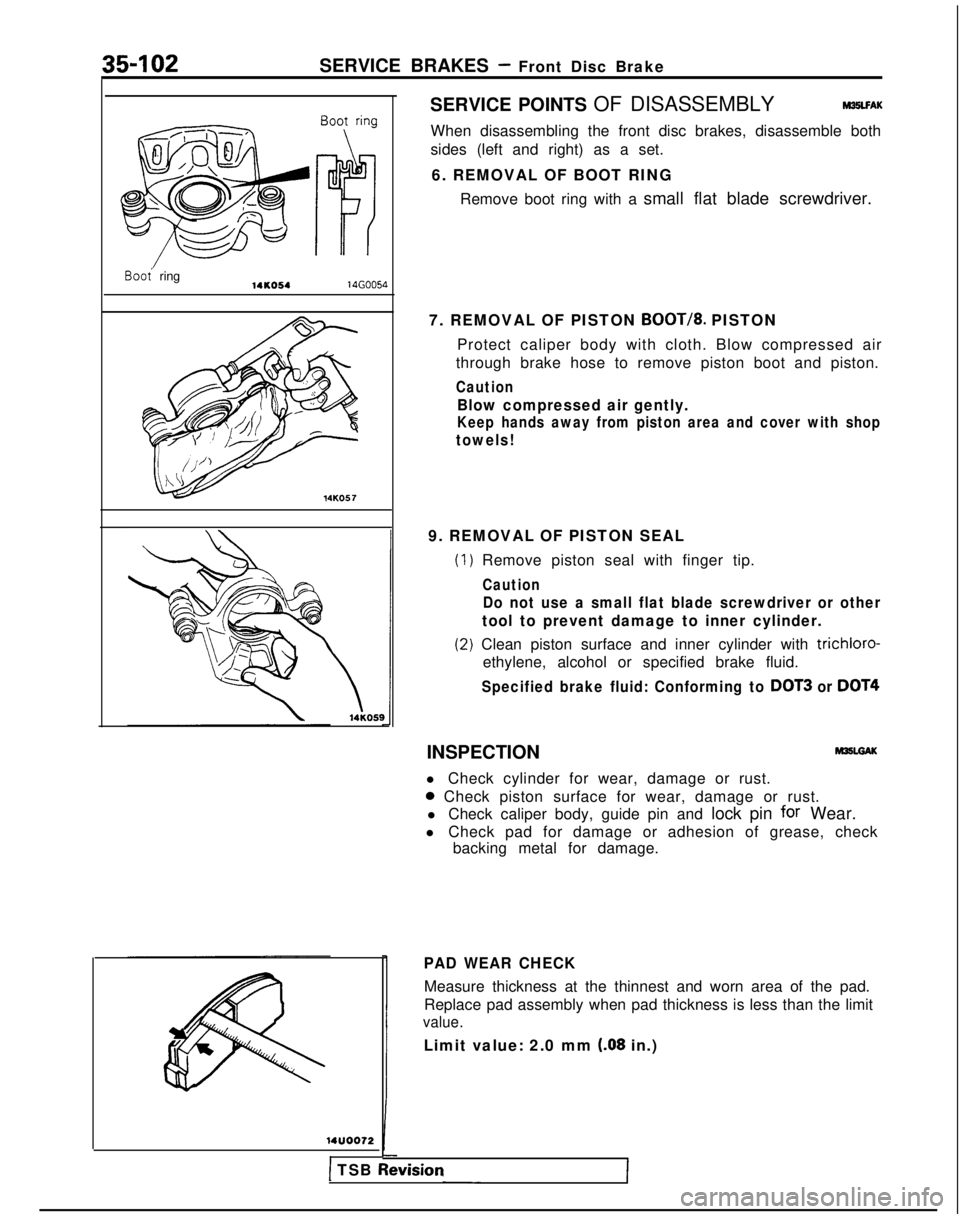
When disassembling the front disc brakes, disassemble both
sides (left and right) as a set.
6. REMOVAL OF BOOT RING Remove boot ring with a small flat blade screwdriver.
7. REMOVAL OF PISTON
BOOT/8. PISTON
Protect caliper body with cloth. Blow compressed air
through brake hose to remove piston boot and piston.
Caution
Blow compressed air gently.
Keep hands away from piston area and cover with shop
towels!
9. REMOVAL OF PISTON SEAL
(1
(2
) Remove piston seal with finger tip.
Caution
Do not use a small flat blade screwdriver or other
tool to prevent damage to inner cylinder.
I) Clean piston surface and inner cylinder with trichloro-
ethylene, alcohol or specified brake fluid.
Specified brake fluid: Conforming to DOT3 or DOT4
INSPECTION
l Check cylinder for wear, damage or rust.
0 Check piston surface for wear, damage or rust.
l Check caliper body, guide pin and lock pin
for Wear.
l Check pad for damage or adhesion of grease, check backing metal for damage.
PAD WEAR CHECK
Measure thickness at the thinnest and worn area of the pad.
Replace pad assembly when pad thickness is less than the limit
value.
Limit value: 2.0 mm (.08 in.)
1 TSB Revrslon
Page 1225 of 1273
35-104SERVICE BRAKES - Front Disc Brake
64-86 Nm46-62 ft.lbs.
46-62 ft.lbs.
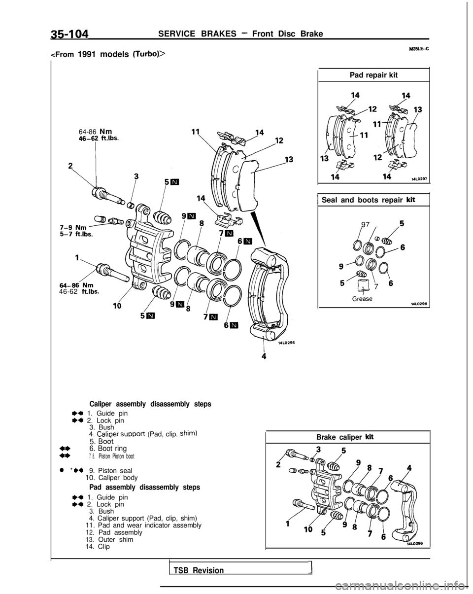
Caliper assembly disassembly steps
W+ 1. Guide pinI)4 2. Lock pin 3. Bush
4. Calioer
support (Pad, clip. shim)
5. Bodt
4*6. Boot ring::7. 8.Piston Piston boot
l * +*9. Piston seal10.Caliper body
Pad assembly disassembly steps
+4 1. Guide pin+4 2. Lock pin3.Bush
4. Caliper support (Pad, clip, shim)
11. Pad and wear indicator assembly
12.Pad assembly13.Outer shim14.Clip Pad repair kit
lhvi14LO7.97
1 Seal and boots repair kit
Greke
97
5
kJd
@
/oy6
osPQ q97 6__ --.
Brake caliper kit
TSBRevision1
Page 1227 of 1273
35-106SERVICE BRAKES - Front Disc Brake
SERVICE POINTS OF DISASSEMBLYM35LFAL
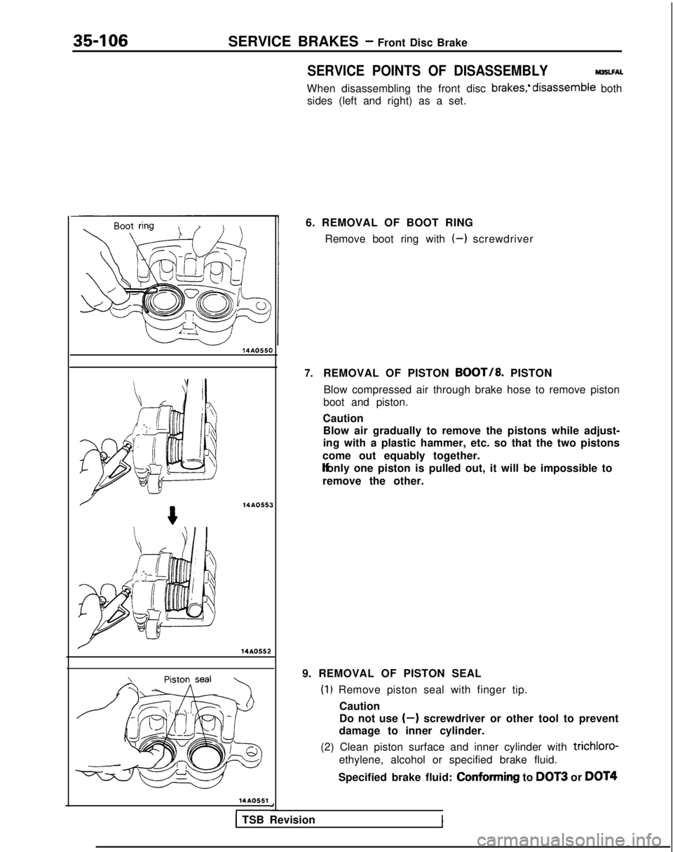
When disassembling the front disc brakes;disassemble both
sides (left and right) as a set.
14AO550 14AO55
14AO551
I 3a-
6. REMOVAL OF BOOT RING
Remove boot ring with
(-) screwdriver
7.REMOVAL OF PISTON BOOT/8. PISTON
Blow compressed air through brake hose to remove piston
boot and piston.
Caution Blow air gradually to remove the pistons while adjust-
ing with a plastic hammer, etc. so that the two pistons
come out equably together. lf only one piston is pulled out, it will be impossible to
remove the other.
9. REMOVAL OF PISTON SEAL
(1) Remove piston seal with finger tip. Caution
Do not use
(-) screwdriver or other tool to prevent
damage to inner cylinder.
(2) Clean piston surface and inner cylinder with
trichloro-
ethylene, alcohol or specified brake fluid.
Specified brake fluid: Conforming
to
DOT3 or DOT4
1 TSB Revision
Page 1233 of 1273
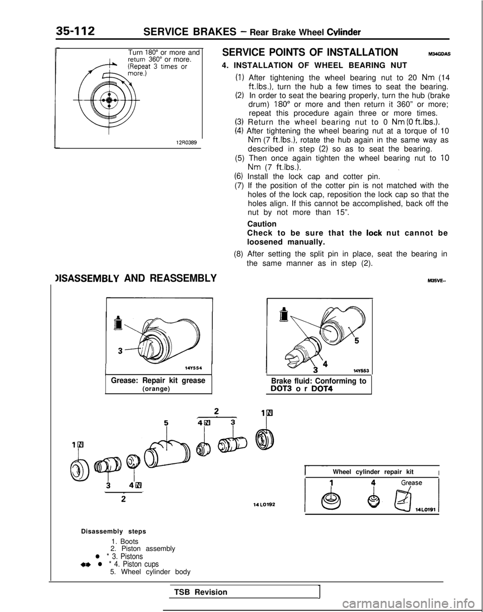
35-112SERVICE BRAKES - Rear Brake Wheel Cylinder
Turn 180” or more and360” or more.SERVICE POINTS OF INSTALLATIONm34obw
4. INSTALLATION OF WHEEL BEARING NUT
12R0389
(1) After tightening the wheel bearing nut to 20 Nm (14ft.lbs.),
turn the hub a few times to seat the bearing.
(2)In order to seat the bearing properly, turn the hub (brake
drum)
180” or more and then return it 360” or more;
repeat this procedure again three or more times.
(3) Return the wheel bearing nut to 0 Nm (0 ft.lbs.).
(4) After tightening the wheel bearing nut at a torque of 10
Nm (7
ft.lbs.),
rotate the hub again in the same way as
described in step
(2) so as to seat the bearing.
(5) Then once again tighten the wheel bearing nut to
10
Nm (7 ft.lbs.).
_(6) Install the lock cap and cotter pin.
(7) If the position of the cotter pin is not matched with the holes of the lock cap, reposition the lock cap so that theholes align. If this cannot be accomplished, back off the
nut by not more than 15”.
Caution
Check to be sure that the
lock nut cannot be
loosened manually.
(8) After setting the split pin in place, seat the bearing in the same manner as in step (2).
IISASSEMBLY AND REASSEMBLY
I
-14Y554
Grease: Repair kit grease(orange)Brake fluid: Conforming toDOT3 or DOT4 14
LO192
hl35VE-
I- ~~Wheel cylinder repair kitI
Disassembly steps
1. Boots
2. Piston assembly
l * 3. Pistons+* l * 4. Piston cups5. Wheel cylinder body
TSB Revision
1
Page 1238 of 1273
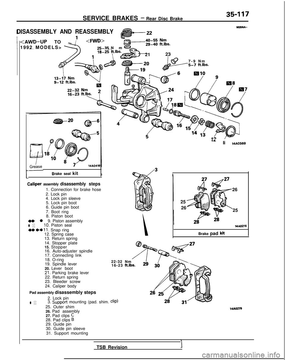
SERVICE BRAKES - Rear Disc Brake35-117
1
3-
j; 21
23
DISASSEMBLY AND REASSEMBLY
t
MISNA-
7-9 N
m
‘5-7 ftlbs.
Brake seal kitL
Caliper assembly disassembly
steps
1. Connection for brake hose
2. Lock pin
4. Lock pin sleeve 5. Lock pin boot
6. Guide pin boot
7. Boot ring 8. Piston boot
41) l 9. Piston assembly
l *10. Piston seal
4* *+ 11. Snap ring
12. Spring case
13. Return spring
14. Stopper plate
15. Stopper16. Auto-adjuster spindle
17. Connecting link
18. O-ring
19. Spindle lever
20. Lever boot
21. Parking brake lever
22. Return spring
23. Bleeder screw
24. Caliper body
Pad assembly disassembly steps
l *
2. Lock pin
3. Support
mounting (pad. shim. clip)
25. Outer shim
26. Pad assembly27. Pad clips
C28. Pad clips B29. Guide pin30. Guide pin sleeve
31. Support mounting
ib!!?I ??-=A ?-18Ib.'+
IL Ii14AO569
I
26
25 26 25 14AOZlg
Brake pad
kit
22-32 Nm 16-23 ft.lbs. 14AO279
TSB Revision
I
Page 1240 of 1273
SERVICE BRAKES - Rear Disc Brake35-119
/14R0062
WUOO72
SERVICE POINTS OF DISASSEMBLYMSNBAE
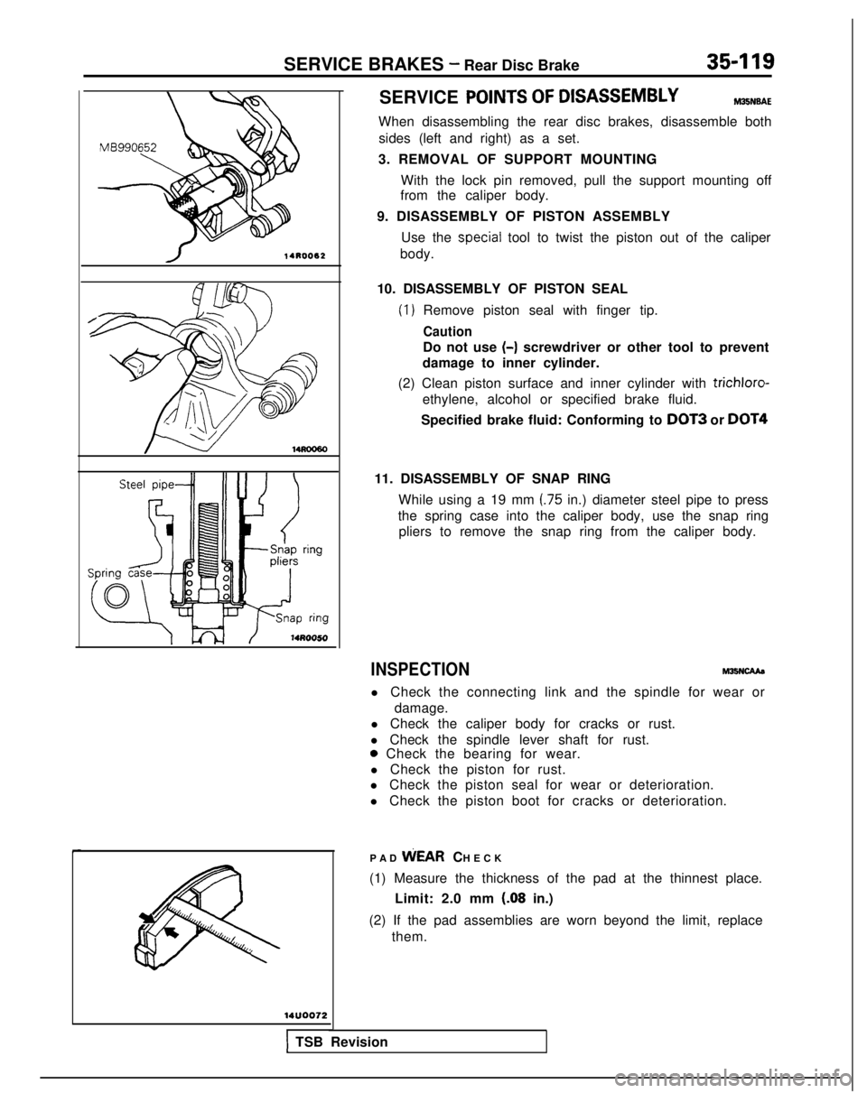
When disassembling the rear disc brakes, disassemble both
sides (left and right) as a set.
3. REMOVAL OF SUPPORT MOUNTING With the lock pin removed, pull the support mounting off
from the caliper body.
9. DISASSEMBLY OF PISTON ASSEMBLY Use the
special tool to twist the piston out of the caliper
body.
10. DISASSEMBLY OF PISTON SEAL
(1) Remove piston seal with finger tip.
Caution
Do not use (-)
screwdriver or other tool to prevent
damage to inner cylinder.
(2) Clean piston surface and inner cylinder with trichloro-
ethylene, alcohol or specified brake fluid.
Specified brake fluid: Conforming to
DOT3 or DOT4
11. DISASSEMBLY OF SNAP RING
While using a 19 mm
(.75 in.) diameter steel pipe to press
the spring case into the caliper body, use the snap ring pliers to remove the snap ring from the caliper body.
INSPECTIONM26NcAAa
l Check the connecting link and the spindle for wear or
damage.
l Check the caliper body for cracks or rust.
l Check the spindle lever shaft for rust.
0 Check the bearing for wear.
l Check the piston for rust.
l Check the piston seal for wear or deterioration.
l Check the piston boot for cracks or deterioration.
PAD WEAR
CHECK
(1) Measure the thickness of the pad at the thinnest place. Limit: 2.0 mm
(.08 in.)
(2) If the pad assemblies are worn beyond the limit, replace them.
1 TSB Revision
Page 1262 of 1273
ALPHABETICAL INDEX1
A
ABS
Checking by the ABS Warnrng Light................
. 35-68-l
Troubleshooting ...........................
35-l 5-l
ABS POWER RELAY, Chec
k 35-74-l
ACCELERATOR CABLE
Inspection and Adjustment
13-398-l
Inspection and Adjustment
ACCELERATOR SWITCH, Inspection and Adjustment 13-329-I
A/C COMPRESSOR CLUTCH RELAY
On-vehicle Inspection
.............
. 13-285-l
On-vehrcle
Inspection
. 13-83-t
On-vehicle Inspection
. 13-176-l
ACTIVE-ECS ON-BOARD DIAGNOSTIC, Check......
. 338-88-I
ACTIVE-ECS RELAY.......................
. 338-141
-I
ACTIVE-ECS SENSOR....
.
...... ............ 338-138-I
ACTIVE-ECS SYSTEM
Checking by Using Alarm Light
.................
. 338-87-I
Operation Check ........................... 338-90-I
AERO PARTS..
.
........................... 51-18-l
AIR CLEANER...............................
. 15-9-I
AIR CLEANER ELEMENT
Inspection and Replacement
....................
. 15-6-l
Maintenance .......................... 00-39-l
AIR COMPRESSOR..........................
. 338-125-I
AIR CONDITIONING SWITCH
Emission control
...........................
.
17-21 -I
Heater, Air
Conditionrng
and Ventilation .............. 55-29-l
On-vehicle Inspection
On-vehicle Inspection
. 13-83-l
On-vehicle Inspection
. 13-176-l
AIR TUBE..............
.
....................... 338-133-I
ALARM LIGHT, Check. ......................... 338-87-I
ALARM SYSTEM, Theft ..........................
54-165-11
ALIGNMENT
Front Wheel, Adjustment .......................
. 33A-5-l
Rear
Wheel, inspection
. 34-23-l
Rear Wheel, Inspection
. 34-5-l
ANTENNA ......................................
54-153-11
ANTI-LOCK BRAKING SYSTEM, Troubleshooting .........
.
35-15-1
ARM
Lower
. 338-103-I
Lower
.
33A-10-I
Lower
................... 34-28-l
Torsion
.
338-l 19-l
Torsion
...................34-l 5-lTrailing
................. 34-31-l
Upper
.................. 34-28-l
AUDIO
SYSTEM................
.
.................
54-l 12-11
AUTO-CRUISE CONTROL. ..........................
. 13-408-I
AUTO-CRUISE CONTROL INDIVIDUAL PARTS, inspection..
. 13-401-I
AUTO-CRUISE CONTROL SYSTEM...................
. 13-332-l
AUTO-CRUISE CONTROL SYSTEM, Inspection..........
. 13-397-l
AUTOMATIC TRANSAXLE, Maintenance ................. 00-43-I
AXLE
Rear, Maintenance
...............................
. 00-45-I
Torsion
.
338-l 19-l
Torsion
.
......................... 34-15-l
AXLE HUB
Rear
Rear CFWD-Rear
Drum Brakes> ................... 27-6-l
AXLE SHAFT
.
27-17-1
B
BACKLASH. Total, Rear Axle, Check
. 27-15-l
BALL JOINT
Rotation Starting Torque Check ...................... 378-8-I
Tie Rod End, Staning Torque Check .................. 37A-15-l
Tie Rod End, Variation Check ....................... 37A-15-l
BALL JOINT SEALS, Maintenance ..................... 00-45-I
BAR
Stabilizer
. 338-106-I
Stabilizer
. 33A-13-l
Stabilizer
. 34-37-l
BAROMETRIC PRESSURE SENSOR
On-vehicle Inspection
................
. 13-266-l
On-vehicle Inspection
On-vehicle Inspection
. 13-154-l
BASIC IDLE SPEED
Adjustment
...........................
. 13-245-l
Adjustment
Adjustment
. 13-133-l
BATTERY.........................................
.
54-2-11
BATTERY, Flat Remedy.
.............................
. 35-75-l
BEARING
Wheel, Adjustment
. 338-87-I
Wheel, Adjustment
BELT
Drive, Compressor, Adjustment
....................
. 55-17-l
Drive (For Water Pump and Generator), Maintenance ..... 00-41-I
Drive, Tension Adjustment
Drive, Tension Adjustment
Seat..........................................
. 52-39-l
Timing
Timing
. 11-34-l
Timing, Maintenance ............................... 00-40-I
Timing, Tension Adjustment
BLEEDING
Clutch
..........................................
. 21-6-l
4ws...........................................
. 370-4-I
Service Brakes. .................................. 35-57-l
Steering ........................................ 37A-22-l
BLOWER..........................................
. 55-32-l
BOOSTER
Brake
.........................................
. 35-85-l
Brake, Operating Inspection ......................... 35-54-l
BOOST METER, On-vehicle Inspection
BOOTS, Drive Shaft, Maintenance ....................... 00-45-I
BRAKE
Disc, Front
......................................
. 35-94-l
Disc, Rear.....................................
.
35-l 14-l
BRAKE BOOSTER
...................................
. 35-85-l
BRAKE BOOSTER, Operating Inspection .................. 35-54-l
BRAKE DISC
Front, Run-out Check.
.............................
. 35-63-l
Front, Run-out Correction ........................... 35-64-l
Front, Thickness Check ............................. 35-65-l
Rear, Run-out Check ............................... 35-66-l
Rear, Run-out Correction. ........................... 35-66-l
Rear, Thickness Check............................
. 35-66-l
BRAKE DRUM, tnside
Diameter, Check ................... 35-67-l
BRAKE FLUID LEVEL SENSOR, Check...................
. 35-54-l
BRAKE FLUID PRESSURE SWITCH
AWD-ABS (Up to 1991 Models)
....................
.
35-133-l
AWD-ABS
(Up to 1991 models), Check ...............
. 35-75-l
BRAKE HOSES, Maintenance ........................... 06-45-t
BRAKELINE
........................................
35-87-l