Page 210 of 1273

13-68 FUEL SYSTEM -On-Vehicule Inspection of MFI Components
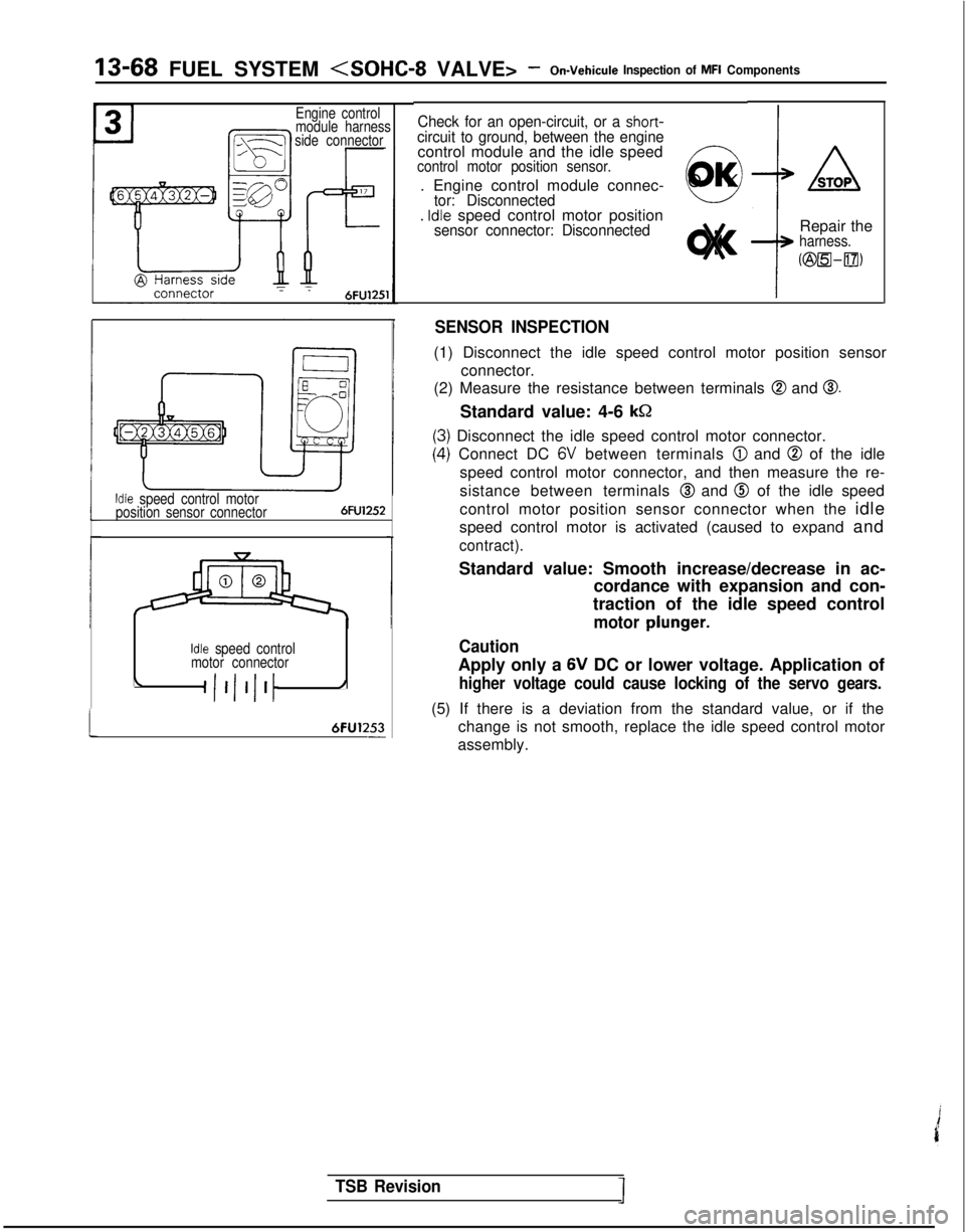
Engine control
module harness
side connectorCheck for an open-circuit, or a short-circuit to ground, between the enginecontrol module and the idle speedcontrol motor position sensor.
. Engine control module connec-tor: Disconnected. Idle speed control motor positionsensor connector: Disconnected
0
O
K
1
ASTOP
i
Repair theharness.
KzEwDlfl,
!
Idle speed control motor
position sensor connector6FU1252
Idle speed control
motor connector
\A 6FU1253
-
SENSOR INSPECTION
(1) Disconnect the idle speed control motor position sensor
connector.
(2) Measure the resistance between terminals
@ and 0.
Standard value: 4-6 k&2
I) Disconnect the idle speed control motor connector.
.) Connect DC 6V between terminals @ and @ of the idle
speed control motor connector, and then measure the re-
sistance between terminals
@ and @ of the idle speed
control motor position sensor connector when the idle
speed control motor is activated (caused to expand and
contract).
Standard value: Smooth increase/decrease in ac-
cordance with expansion and con-
traction of the idle speed control
motor plunger.
Caution
Apply only a 6V DC or lower voltage. Application of
higher voltage could cause locking of the servo gears.
(5) If there is a deviation from the standard value, or if the change is not smooth, replace the idle speed control motor
assembly.
TSB Revision
Page 235 of 1273

FUEL SYSTEM -On-Vehicule Inspection of MFI Components13-93
IDLE SPEED CONTROL MOTOR (DC MOTOR)
Idle speed control9-/
motor
/---T-,I \
6FUO852
i id l
-
Idle speed -control
r1 /&46~U0838
Harness side@ connector
< 1989 models>
Enoine control module
M13YUAF
Component sideconnector
!
a,Yg
z.-t;Fs 8
B
12
d
Idle
speed
control
Mmotor
lFUO495
Engine control module connector
1
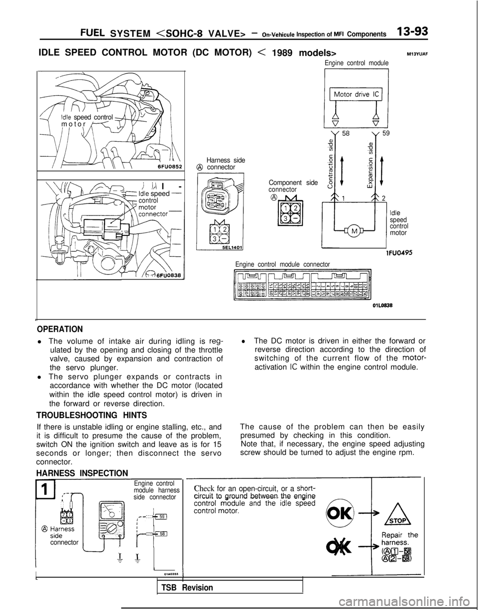
OPERATION
l The volume of intake air during idling is reg-
ulated by the opening and closing of the throttle
valve, caused by expansion and contraction of
the servo plunger.
l The servo plunger expands or contracts in accordance with whether the DC motor (located
within the idle speed control motor) is driven in
the forward or reverse direction.
lThe DC motor is driven in either the forward or reverse direction according to the direction of
switching of the current flow of the motor-
activation
IC within the engine control module.
TROUBLESHOOTING HINTS
If there is unstable idling or engine stalling, etc., and
it is difficult to presume the cause of the problem,
switch ON the ignition switch and leave as is for 15
seconds or longer; then disconnect the servo
connector.
HARNESS INSPECTION
The cause of the problem can then be easily presumed by checking in this condition.Note that, if necessary, the engine speed adjusting
screw should be turned to adjust the engine rpm.
Iconnector
Engine control
module harness
side connector
IIrIsEI
r- r-
II01.03,~I
TSB Revision
Check for an open-circuit, or a short-circuit to ground between the engine
Page 250 of 1273

13-108 FUEL SYSTEM
VALVE>- On-Vehicule Inspection of MFI Components
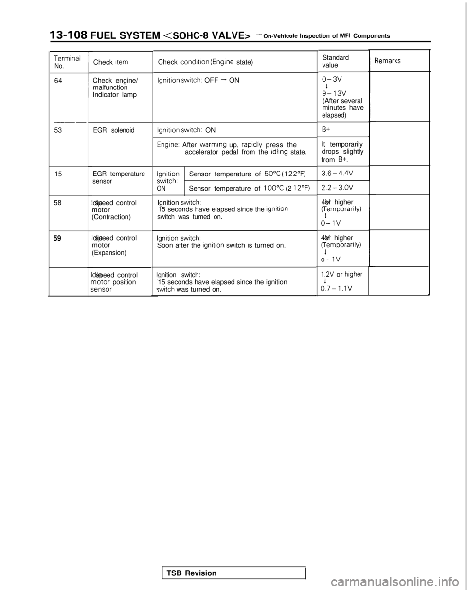
TermrnalNo.
64
__-
53
15
58
59
Check Item
Check engine/
malfunction
Indicator lamp
EGR solenoid
EGR temperature
sensor Idle speed control
motor
(Contraction) Idle speed control
motor
(Expansion)
II
dle speed controlrnotor positions
;ensor
Check
condrtron (Engrne state)
lgnrtron swatch: OFF - ON
lgnrtron swatch: ON
Engine: After warming
up, raprdly press the
accelerator pedal from the rdlrng state.
lgnrtronSensor temperature of 50°C (122°F)swrtch,ONSensor temperature of 100°C (2 12°F)
Ignition swatch:15 seconds have elapsed since the IgnitlOnswitch was turned on.
Ignition switch:Soon after the ignitron switch is turned on.
gnition switch:15 seconds have elapsed since the ignitionswitch was turned on.
Standardvalue
o-3v
9’- 13v(After several
minutes have
elapsed)
B+
It temporarily
drops slightly
from
B+.
3.6-4.4v
2.2- 3.OV 4V or higher
(:emporarily)
o-1v
4V or higher
(:emporarily)
o-
IV
1.2V or higher
A- 1.1v
qemarks
TSB Revision
Page 941 of 1273

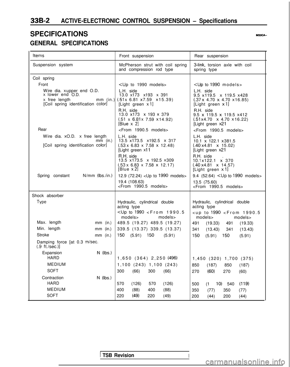
33B-2ACTIVE-ELECTRONIC CONTROL SUSPENSION - Specifications
SPECIFICATIONSM33CA-
GENERAL SPECIFICATIONS
ItemsFront suspensionRear suspension
Suspension system McPherson strut with coil spring 3-link,
torsion axle with coil
and compression rod type spring type
Coil spring
Front
>
Wire dia. x upper end O.D.
L.H. side L.H. side
x lower endO.D.13.0 x 173 x 193 x 391
9.5 x 119.5 x
119.5 x 428x free length
mm (in.) (51
x 6.81 x 7.59 x 15.39)(.37
x
4.70 x 4.70 x 16.85)
[Coil spring identification color1[Light green x II[Light green x
11
R.H. side R.H. side
13.0 x 173 x 193 x 379
9.5 x
119.5 x
119.5 x 412
;;lexx6$1 x 7.59
x 14.92) (51
x 4.70 x
4.70 x 16.22)U[Light green
x 21
Rear
W
ire dia. x O.D.
x free lengthL.H. side
L.H. side
mm(in.)13.5 x 173.5 x 192.5 X 317
10.1 x
122.1 x 381.5
[Coil spring identification color]
(.53 x 6.83 x 7.58
x
12.48)(.40 x 4.81 x
15.02)
[Light green x 11
[Light green x 21
R.H. side
R.H. side
13.5 x 173.5 x 192.5 x 30910.1
x 122.1 x. 370(53 x 6.83 x 7.58
x
12.17)(.40 x 4.81 x
14.57)
[Blue x 21[Light green
x
11
Spring constant N/mm (Ibs./in.)12.9 (72.24) 9.4 (52.64)
19.4 (108.63) 13.5 (75.60)
Shock absorber Type
Hydraulic, cylindrical double
Hydraulic, cylindrical double
acting type acting type
5
1990
5
models> models>
models> models>
Max. length mm
(in.)489.5 (19.27) 489.5 (19.27) 491 (19.33) 491 (19.33)
Min. length mm
(in.)339.5 (13.37) 339.5 (13.37) 341 (13.43) 341 (13.43)
Stroke mm
(in.)150 (5.91) 150 (5.91)150 (5.91) 150 (5.91)
Damping force [at 0.3
m/set.(.9 ft./sec.)l
ExpansionN (Ibs.)
HARD
1,650 (364) 2,250 (496)1,450 (320) 1,700 (375
)
MEDIUM 1,100 (243) 1,100 (243) 850 (187) 850 (187)
SOFT300 (66) 300 (66) 270 (60) 270 (60)
Contraction
N (Ibs.)
HARD
570 (126) 570 (126) 500 (1 IO) 540 (119)
MEDIUM400 (88) 400 (88) 350 (77) 350 (77)
SOFT220 (49) 220 (49)200 (44) 200 (44)
1 TSB RevisionI