1989 MITSUBISHI GALANT catalytic converter
[x] Cancel search: catalytic converterPage 36 of 1273
00-34GENERAL- Lubrication and Maintenance
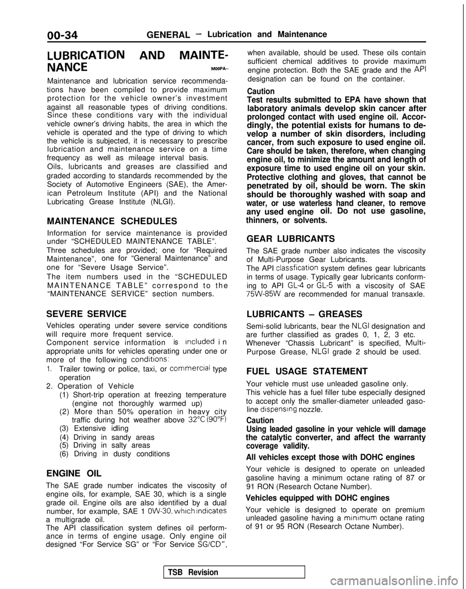
LUBRICATION AND
MAINTE-
NANCEMOOPA-
Maintenance and lubrication service recommenda-
tions have been compiled to provide maximum protection for the vehicle owner’s investment
against all reasonable types of driving conditions. Since these conditions vary with the individual
vehicle owner’s driving habits, the area in which the
vehicle is operated and the type of driving to which
the vehicle is subjected, it is necessary to prescribe lubrication and maintenance service on a time
frequency as well as mileage interval basis.
Oils, lubricants and greases are classified and
graded according to standards recommended by the Society of Automotive Engineers (SAE), the Amer-
ican Petroleum Institute (API) and the National
Lubricating Grease Institute (NLGI).
MAINTENANCE SCHEDULES Information for service maintenance is provided
under “SCHEDULED MAINTENANCE TABLE”.
Three schedules are provided; one for “Required Maintenance”, one for “General Maintenance” and
one for “Severe Usage Service”.
The item numbers used in the “SCHEDULED MAINTENANCE TABLE” correspond to th
e
“MAINTENANCE SERVICE” section numbers.
SEVERE SERVICE
Vehicles operating under severe service conditions
will require more frequent service. Component service information
isIncluded i
n
appropriate units for vehicles operating under one or
more of the following conditrons:
1.Trailer towing or police, taxi, or
commerciai
type
operation
2. Operation of Vehicle (1) Short-trip operation at freezing temperature(engine not thoroughly warmed up)
(2) More than 50% operation in heavy city traffic during hot weather above
32°C (90°F)
(3) Extensive idling
(4) Driving in sandy areas
(5) Driving in salty areas
(6) Driving in dusty conditions
ENGINE OIL
The SAE grade number indicates the viscosity of engine oils, for example, SAE 30, which is a single
grade oil. Engine oils are also identified by a dual number, for example, SAE 1
OW-30, which Indicates
a multigrade oil.
The API classification system defines oil perform- ance in terms of engine usage. Only engine oil
designed “For Service SG” or “For Service
SGKD”,
when available, should be used. These oils contain
sufficient chemical additives to provide maximum
engine protection. Both the SAE grade and the API
designation can be found on the container.
Caution
Test results submitted to EPA have shown that
laboratory animals develop skin cancer after
prolonged contact with used engine oil. Accor-
dingly, the potential exists for humans to de-
velop a number of skin disorders, including
cancer, from such exposure to used engine oil.
Care should be taken, therefore, when changing engine oil, to minimize the amount and length of
exposure time to used engine oil on your skin.
Protective clothing and gloves, that cannot be
penetrated by oil, should be worn. The skin
should be thoroughly washed with soap and
water, or use waterless hand cleaner, to remove
any used engine oil. Do not use gasoline,
thinners, or solvents.
GEAR LUBRICANTS
The SAE grade number also indicates the viscosity of Multi-Purpose Gear Lubricants.
The API classfication
system defines gear lubricants
in terms of usage. Typically gear lubricants conform-
ing to API
GL-4 or GL-5 with a viscosity of SAE 75W-85W
are recommended for manual transaxle.
LUBRICANTS
- GREASES
Semi-solid lubricants, bear the
NLGI designation and
are further classified as grades 0, 1, 2, 3 etc.
Whenever “Chassis Lubricant” is specified,
Multi-
Purpose Grease, NLGI grade 2 should be used.
FUEL USAGE STATEMENT
Your vehicle must use unleaded gasoline only.
This vehicle has a fuel filler tube especially designed
to accept only the smaller-diameter unleaded gaso- line
dispensrng nozzle.
Caution
Using leaded gasoline in your vehicle will damage
the catalytic converter, and affect the warranty
coverage validity.
All vehicles except those with DOHC engines
Your vehicle is designed to operate on unleaded
gasoline having a minimum octane rating of 87 or
91 RON (Research Octane Number).
Vehicles equipped with DOHC engines
Your vehicle is designed to operate on premiumunleaded gasoline having a minimum
octane rating
of 91 or 95 RON (Research Octane Number).
TSB Revision
Page 340 of 1273
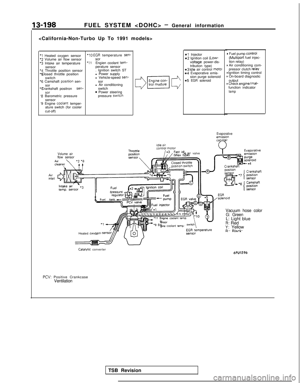
13-198FUEL SYSTEM
*I Heated oxygen sensor *IO
EGR temperature sen-*2 Volume air flow sensor
sor‘3 Intake air temperature
*I 1Engien coolant tem-sensor
perature sensor‘4 Throttle position sensor . Ignition switch ST*5 Closed throttle position
l Power supply
switch l Vehicle-speed sen-
‘6 Camshaft
posltion
sen- sor
sor l Air conditioning“7 Crankshaft positron sen-
switch
SOT0 Power steering‘8 Barometric pressure pressure switch
sensor
‘9 Engine coolant
temper-
ature switch (for cooler
cut-off)
*l Injector*2 Ignition coil (Low-
voltage
power-dis-
tribution type)
*3 idle air control mot01*4 Evaporative emis- sion purge solenoid
*5 EGR solenoid
) Fuel pump control
(Multiport
fuel injec-
tion relay)
I Air conditioning com- pressor clutch relay I Ignition timing control
) On-board diagnostic
output
) Check enginejmal-
function indicator
lamp
Evaporativeemissioncanister
Volume air
flow sensorA..\
II
oressure db,Fun, taw”l”‘“‘~
Heated 0~““~” le
ax valve
e”SOrgme coolant temp.
Vacuum hose color
G: Green
L: Light blueR: RedY: YellowR. Rlnrk
Catalytic converter 6FU1596
PCV:
Positive Crankcase
Ventilation
TSB Revision
Page 590 of 1273
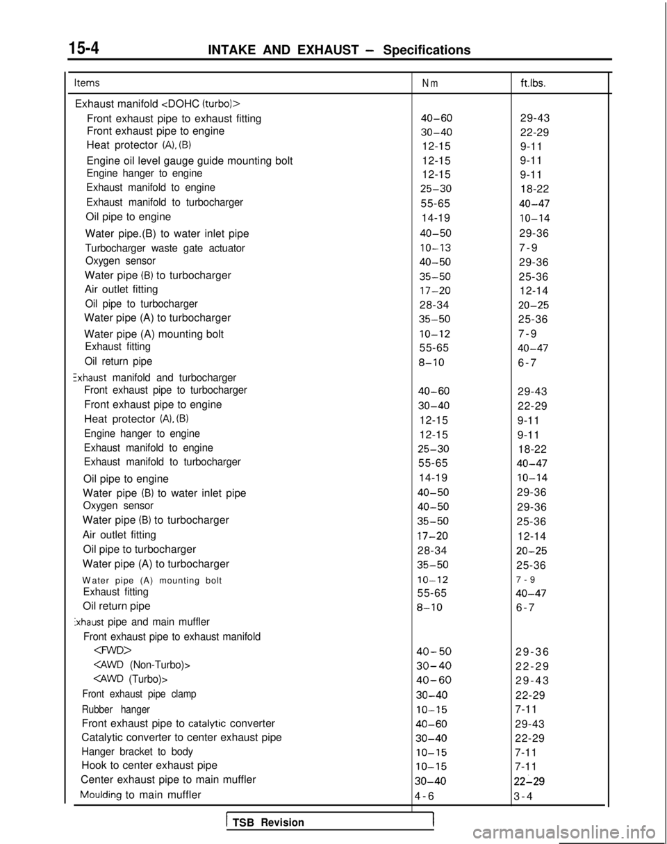
15-4INTAKE AND EXHAUST - Specifications
Items
Exhaust manifold
Front exhaust pipe to exhaust fitting
Front exhaust pipe to engine
Heat protector
(A), (B)
Engine oil level gauge guide mounting bolt
Engine hanger to engine
Exhaust manifold to engine
Exhaust manifold to turbocharger
Oil pipe to engine
Water pipe.(B) to water inlet pipe
Turbocharger waste gate actuator Oxygen sensor
Water pipe (B) to turbocharger
Air outlet fitting
Oil pipe to turbocharger
Water pipe (A) to turbocharger
Water pipe (A) mounting bolt
Exhaust fitting
Oil return pipe
!xhaust manifold and turbocharger
Front exhaust pipe to turbocharger
Front exhaust pipe to engine
Heat protector
(A), (B)
Engine hanger to engine
Exhaust manifold to engine
Exhaust manifold to turbocharger
Oil pipe to engine
Water pipe
(B) to water inlet pipe
Oxygen sensor
Water pipe (B) to turbocharger
Air outlet fitting Oil pipe to turbocharger
Water pipe (A) to turbocharger
W
ater pipe (A) mounting bolt
Exhaust fitting
Oil return pipe
Exhaust pipe and main muffler
Front exhaust pipe to exhaust manifold
Front exhaust pipe clamp
Rubber hanger
Front exhaust pipe to catalytic converter
Catalytic converter to center exhaust pipe
Hanger bracket to body
Hook to center exhaust pipe
Center exhaust pipe to main muffler
Moulding to main muffler
1 TSBRevision
Nm
40-60
30-40
12-15
12-15
12-15
25-30
55-65
14-19
40-50
IO-13
40-50
35-50
17-20
28-34
35-50
IO-12
55-65
8-10
40-60
30-40
12-15
12-15
25-30
55-65
14-19
40-50
40-50
35-50
17-20
28-34
35-50
IO-12
55-65
8-10
40-50
30-40
40-60
30-40
IO-15
40-60
30-40
IO-15
IO-15
30-40
4-
6
1
ft.lbs.
29-43
22-29
9-11
9-11
9-11
18-22
40-47
10-14
29-36
7-
9
29-36
25-36 12-14
20-25
25-36
7-
9
40-47
6-
7
29-43
22-29
9-11
9-11 18-22
40-47
IO-14
29-36
29-36
25-36
12-14
20-25
25-36
7-
9
40-47
6-
7
29-36
22-29
29-43
22-29
7-11
29-43
22-29
7-11
7-11
22-29
3-
4
Page 618 of 1273
15-32INTAKE AND EXHAUST - Exhaust Pipe and Main Muffler
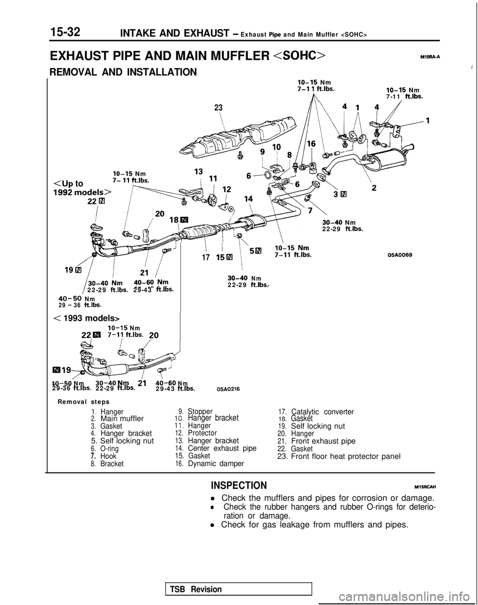
EXHAUST PIPE AND MAIN MUFFLER
iREMOVAL AND INSTALLATION
IO-15 Nm7-l 1 ft.lbs.
h
lo-15 Nm
7-11 ft.lbs.
23 30-40
Nm
22-29
ft.lbs.
’1715lIl 30-40
Nm
22-29ftlbs.29-43ft.lbs.22-29ft.lbs.
40-50Nm29 - 36ftlbs.
05A0069
< 1993 models>
IO-15 Nm22.1
7-11
ftlbs.20
40-50
Nm30-40Nm2140-60Nm29-36ft.lbs.22-29 ft.lbs.29-43
ftlbs.05A0216
Removal steps
1.Hanger2.Main muffler3.Gasket4.Hanger bracket5. Self locking nut6.O-ring7.Hook8.Bracket
9.Stopper
10.Hanger bracket11.Hanger12.Protector13.Hanger bracket14.Center exhaust pipe15. Gasket16.Dynamic damper
17.Catalytic converter18.Gasket19.Self locking nut20.Hanger21.Front exhaust pipe22.Gasket23. Front floor heat protector panel
INSPECTION
MlSRCAH
l Check the mufflers and pipes for corrosion or damage.
lCheck the rubber hangers and rubber O-rings for deterio- ration or damage.
l Check for gas leakage from mufflers and pipes.
TSB Revision
Page 619 of 1273
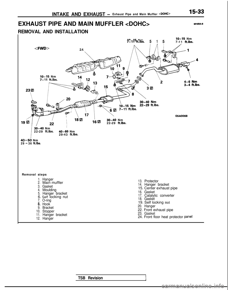
INTAKE AND EXHAUST -Exhaust Pipe and Main Muffler
EXHAUST PIPE AND MAIN MUFFLER
15-33M15R4-8
REMOVAL AND INSTALLATION
IO-15 Nmlo-15 Nm
7-11ft.lbs.5157-11ft.lbs.,
,IO-15
Nm 7-11
ft.lbs.
30-40 Nm
22-29 ft.lbs.
30-40 NmI
22-29 ft.lbs. 40-60
Nm
29-43 ftlbs.
40-50 Nm29 - 36 ft.lbs.
Removal steps
1.Hanger2.Main muffler
3.Gasket4.Moulding5.Hanger bracket6. Self locking nut7.O-ring
8.Hook9.Bracket10.Stopper11.Hanger bracket12.Hanger
13.Protector14.Hanger bracket15. Center exhaust pipe
16.Gasket17.Catalytic converter18.Gasket19. Self locking nut20.Hanger
22. Front exhaust pipe23. Gasket24. Front floor heat protector panel
TSB RevisionI
Page 620 of 1273
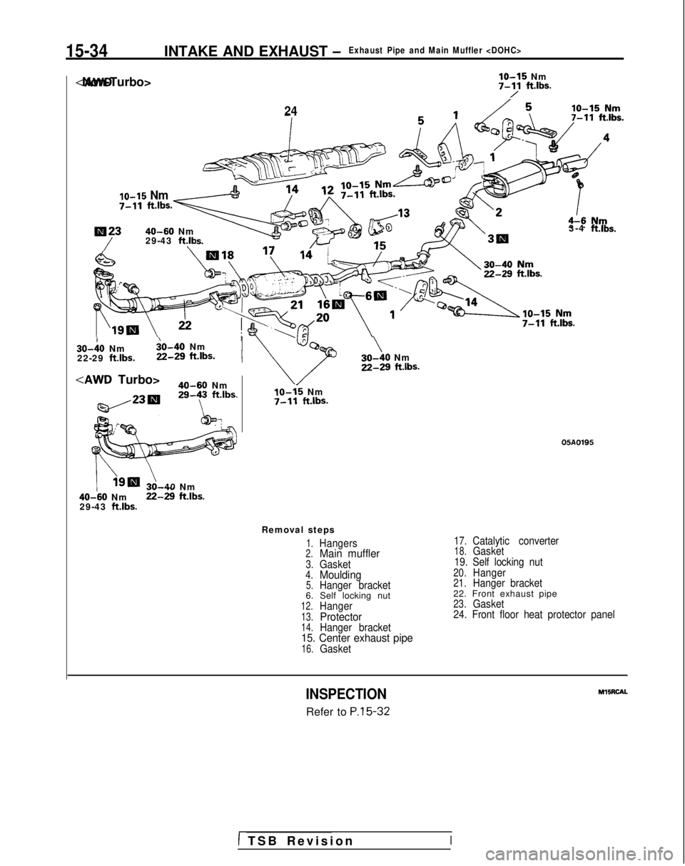
15-34INTAKE AND EXHAUST -Exhaust Pipe and Main Muffler
lo-15 Nm
7-Y ft*lbs.
10-15 Nm
7-11
ft.lbs
24
lN2340-60 Nm
/29-43 ft.lb
3-4 ft.lbs. 30-10
Nm
$0-40 Nm
22-29
ft.lbs. 22-29
ft.lbs.I
40-60 Nm29-y ft.lbs.
/\Ignr ?,40 Nm 40-60
Nm 22-29
ft.lbs.29-43 ft.lbs.
\30-40 NmZ-29 ft.lbs.
IO-15 Nm7-11 ft.lbs.
05A0195
Removal steps
1.Hangers2.Main muffler3.Gasket4.Moulding5.Hanger bracket6. Self locking nut12.Hanger13.Protector14.Hanger bracket15. Center exhaust pipe16.Gasket
17.Catalytic converter18.Gasket
19. Self locking nut
20.Hanger21.Hanger bracket22. Front exhaust pipe23.Gasket
24. Front floor heat protector panel
INSPECTION
Refer to P.15-32 MllRCAL
1 TSB Revisio
n
I
Page 621 of 1273
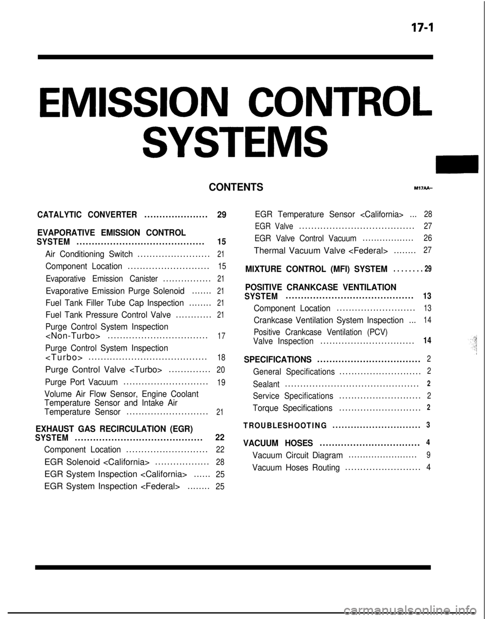
EMISSION CONTROL
SYSTEMS
CONTENTSr.w?API-
CATALYTIC CONVERTER.....................29
EVAPORATIVE EMISSION CONTROL
SYSTEM..........................................15
Air Conditioning Switch........................21
Component Location...........................15
Evaporative Emission Canister................21
Evaporative Emission Purge Solenoid.......21
Fuel Tank Filler Tube Cap Inspection........21
Fuel Tank Pressure Control Valve............21
Purge Control System Inspection
Purge Control System Inspection
.......................................
18
Purge Control Valve
..............20
Purge Port Vacuum............................19
Volume Air Flow Sensor, Engine Coolant
Temperature Sensor and Intake Air
Temperature Sensor
...........................21
EXHAUST GAS RECIRCULATION (EGR)
SYSTEM..........................................22
Component Location...........................22
EGR Solenoid
EGR System Inspection
......25
EGR System Inspection
EGR Temperature Sensor
EGR Valve
......................................27
EGR Valve Control Vacuum..................26
Thermal Vacuum Valve
MIXTURE CONTROL (MFI) SYSTEM. . . . . . . . 29
POSITIVE CRANKCASE VENTILATION
SYSTEM..........................................13
Component Location..........................13
Crankcase Ventilation System Inspection
...14
Positive Crankcase Ventilation (PCV)
Valve Inspection
...............................14
SPECIFICATIONS..................................2
General Specifications...........................2
Sealant............................................2
Service Specifications...........................2
Torque Specifications...........................2
TROUBLESHOOTING.............................3
VACUUM HOSES.................................4
Vacuum Circuit Diagram........................9
Vacuum Hoses Routing.........................4
Page 622 of 1273
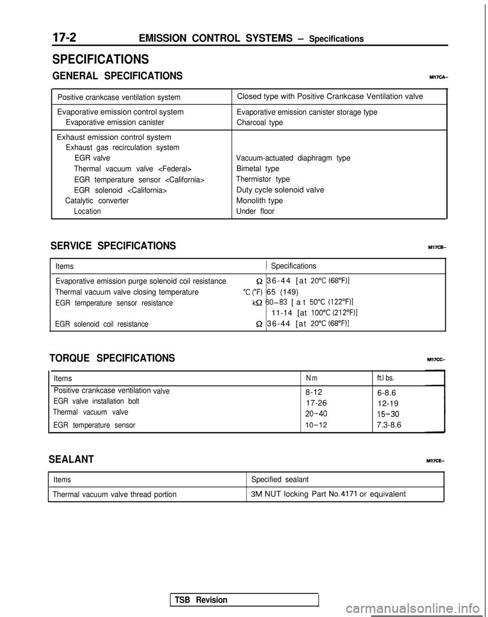
17-2EMISSION CONTROL SYSTEMS - Specifications
SPECIFICATIONS
GENERAL SPECIFICATIONSMl’IcA-
Positive crankcase ventilation system
Evaporative emission control system
Evaporative emission canister
Exhaust emission control system
Exhaust gas recirculation systemEGR valve
Thermal vacuum valve
EGR temperature sensor
EGR solenoid
Catalytic converter
Location
Closed type with Positive Crankcase Ventilation valve
Evaporative emission canister storage type
Charcoal type
Vacuum-actuated diaphragm type Bimetal type
Thermistor type
Duty cycle solenoid valve
Monolith type
Under floor
SERVICE SPECIFICATIONS M17CB-
Items1 Specifications
Evaporative emission purge solenoid coil resistance
Thermal vacuum valve closing temperature
EGR temperature sensor resistance
Q 36-44 [at 20°C (68”F)I
‘C (“F) 65 (149)
kQ 60-83
[at 50°C (122”F)l
11-14 [at 100°C (212”F)l
EGR solenoid coil resistance52 36-44 [at 20°C (68°F))
TORQUE SPECIFICATIONS
ItemsNmft.1 bs.
Positive crankcase ventilationvalve8-12
6-8.6
EGR valve installation bolt17-2612-19
Thermal vacuum valve20-40 15-30
EGR temperature sensorIO-127.3-8.6
SEALANT
Items
Thermal vacuum valve thread portion
Specified sealant3M NUT locking Part No.4171 or equivalent
TSB Revision