1989 MITSUBISHI GALANT clutch
[x] Cancel search: clutchPage 1 of 1273
BACKUP
Service Manual
GRLRNT
1989-1990-1991-1992-1993
Volume 1
Chassis & Mechanical
FOREWORD
This Service Manual has been prepared with thelatest service information available at the time of
publication. It is subdivided into various group cate-
gories and each section contains diagnostic, dis-
assembly, repair, and installation procedures along
with complete specifications and tightening ref-
erences. Use of this manual will aid in properly per-
forming any servicing necessary to maintain or res-
tore the high levels of performance and reliability
designed into these outstanding vehicles.
This BACKUP DSM manual is to be used DNLY as
a SACKUP. please DIJ NOT REDISTRIBUTEWHOLE SECTIONS. This BACKUP was sold to you under the fact that you do indeed
DWNa GENUINE DSM MANUAL. It CANNOT BE considered a REPLACEMENT (Unless your
original
manual was lost or
destroyed.) Please
See
README.TXT
or
README.HTML
for additional
information.
1kyou.
- Gjmpiemym_ay&?h
@
A
.
.”
WE SUPPORT
VOLUNTARY TECHNICIAN
CERTIFICATION THROUGH
Nallonal lnsrltule forAU~~~v3~;VPCT:VE
EXCELLENCE naiLcorn
MITSUBISHIMOTOR SALES OF AMERICA. Inc.
Mltsublshl Motors Corporat!on reserves the right to make changes indesign or to make additions to or Improvements In Its products
wlthout~mposng any obllgatlons upon Itself to install them on its productspreviously manufactured
0 1992 Mitsubishi Motors CorporationRcprintedinUSA
GROUP INDEXMOOAA-
General.........................................................
Engine...........................................................
Fuel................................................................
Cooling.........................................................
Intake and Exhaust..............................
Emission Control....................................
Clutch............................................................
Manual Transaxle..................................
Automatic Transaxle............................
Propeller Shaft........................................
Front Axle..................................................
Rear Axle....................................................
Wheel and Tire.......................................
Power Plant Mount..............................
Front Suspension...................................
Active-Electronic
Control Suspension..............................m
A
Rear Suspension....................................&
Service Brakes.........................................
Parking Brakes........................................
Alphabetical Index.................................
NOTE: Electrical system Information is contained in
Volume 2 “Electrical” of this paired Service Manual.
For overhaul procedures of engines or transmissions,
refer to the separately issued Engine
Service Manual
or Manual/Automatic Transmission Service Manual.
Page 23 of 1273
GENERAL - Special Handling Instructions for AWD Models00-21
Free roller
OOPO038
Axle stand
OOPOO37
Towino hook
Tenslon
bar
Front
eJ
Anchor plate
&-16PO209 14AO198
OOP003E
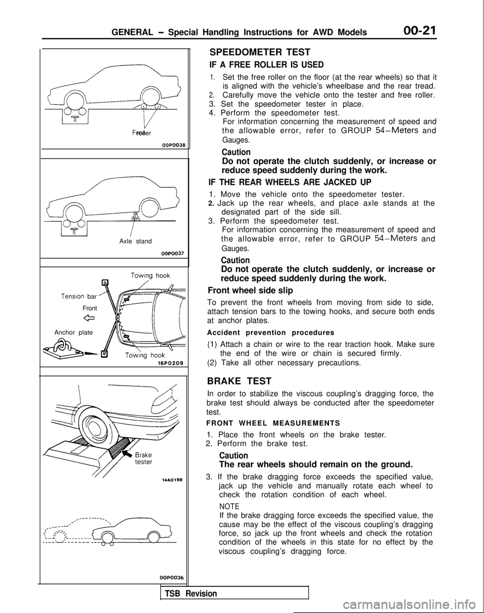
SPEEDOMETER TEST
IF A FREE ROLLER IS USED
1.Set the free roller on the floor (at the rear wheels) so that it
is aligned with the vehicle’s wheelbase and the rear tread.
2.Carefully move the vehicle onto the tester and free roller.
3. Set the speedometer tester in place.
4. Perform the speedometer test. For information concerning the measurement of speed and
the allowable error, refer to GROUP
54-Meters and
Gauges.
Caution
Do not operate the clutch suddenly, or increase or
reduce speed suddenly during the work.
IF THE REAR WHEELS ARE JACKED UP
1. Move the vehicle onto the speedometer tester.
2. Jack up the rear wheels, and place axle stands at the designated part of the side sill.
3. Perform the speedometer test. For information concerning the measurement of speed and
the allowable error, refer to GROUP
54-Meters and
Gauges.
Caution
Do not operate the clutch suddenly, or increase or
reduce speed suddenly during the work.
Front wheel side slip
To prevent the front wheels from moving from side to side, attach tension bars to the towing hooks, and secure both ends
at anchor plates.
Accident prevention procedures (1) Attach a chain or wire to the rear traction hook. Make sure the end of the wire or chain is secured firmly.
(2) Take all other necessary precautions.
BRAKE TEST In order to stabilize the viscous coupling’s dragging force, the
brake test should always be conducted after the speedometer
test.
FRONT WHEEL MEASUREMENTS
1. Place the front wheels on the brake tester.
2. Perform the brake test.
Caution
The rear wheels should remain on the ground.
3. If the brake dragging force exceeds the specified value, jack up the vehicle and manually rotate each wheel tocheck the rotation condition of each wheel.
NOTE
If the brake dragging force exceeds the specified value, the
cause may be the effect of the viscous coupling’s dragging
force, so jack up the front wheels and check the rotation condition of the wheels in this state for no effect by the
viscous coupling’s dragging force.
,
TSB Revision
Page 24 of 1273
00-22GENERAL - Special Handling Instructions for AWD Models
REAR WHEEL MEASUREMENTS
After placing the rear wheels on the brake tester, follow thesame procedures as for the front wheel measurements.
WHEEL BALANCE
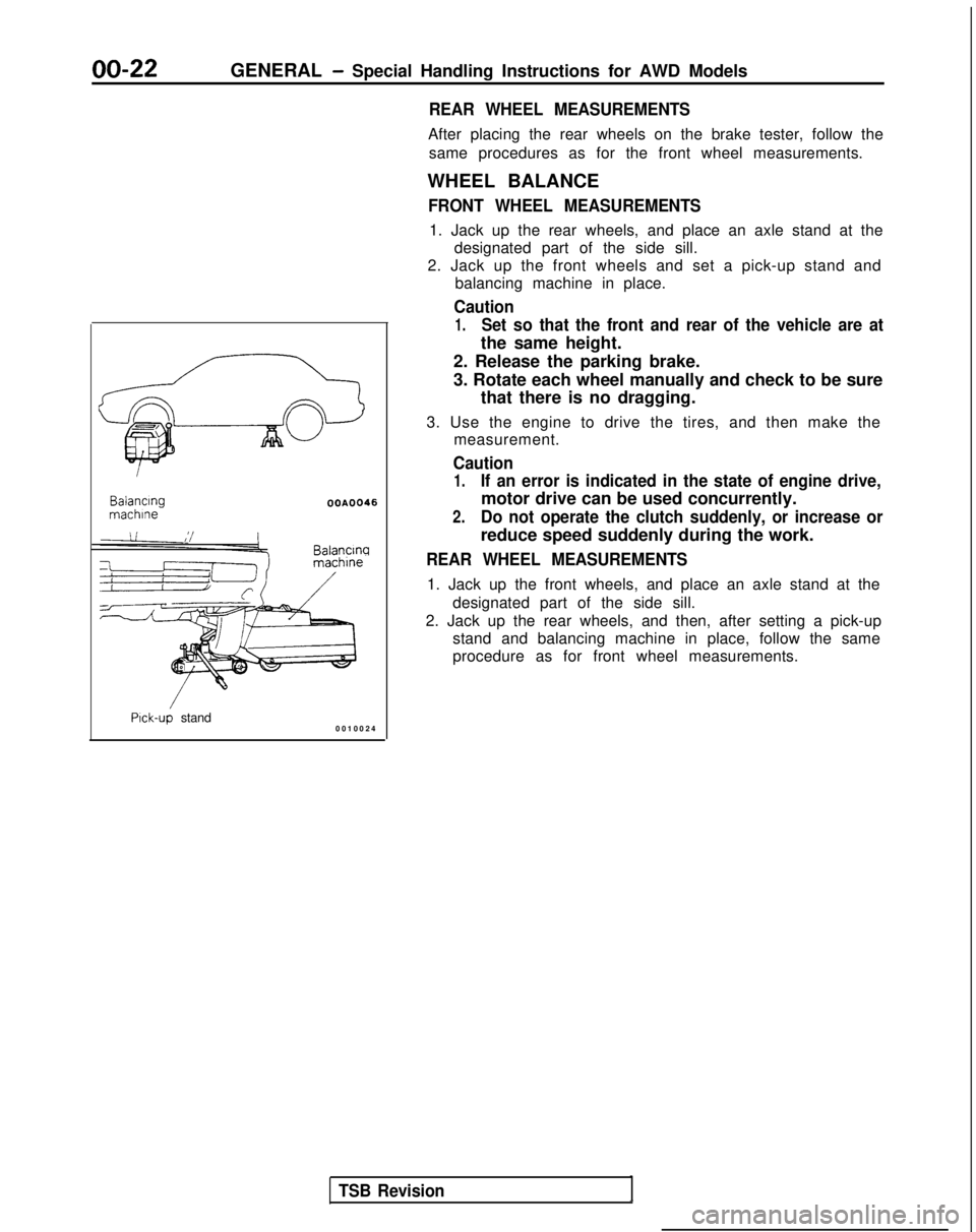
FRONT WHEEL MEASUREMENTS
1. Jack up the rear wheels, and place an axle stand at the designated part of the side sill.
2. Jack up the front wheels and set a pick-up stand and balancing machine in place.
Caution
1.Set so that the front and rear of the vehicle are at
the same height. Balancing
machlne
OOA0046
Balancw
Pick-up stand
0010024
TSB Revision
2. Release the parking brake.
3. Rotate each wheel manually and check to be sure
that there is no dragging.
3. Use the engine to drive the tires, and then make the measurement.
Caution
1.If an error is indicated in the state of engine drive,
motor drive can be used concurrently.
2.Do not operate the clutch suddenly, or increase or
reduce speed suddenly during the work.
REAR WHEEL MEASUREMENTS
1. Jack up the front wheels, and place an axle stand at the
designated part of the side sill.
2. Jack up the rear wheels, and then, after setting a pick-up stand and balancing machine in place, follow the same
procedure as for front wheel measurements.
Page 26 of 1273
00-24GENERAL - General Data and Specifications
ItemsFWDAWD
SOHC Engine DOHC Engine DOHC Engine DOHC Engine
(Non-Turbo)
(Turbo)
Vehicle weight
kg (Ibs.)
Curb weightsMIT
1.2 10 (2.668)1.290 (2,844) or 1.405 (3.097).1,495 (3.296)1.3 10 (2.8881e2
/-v-r1,230 (2.7 12) or
1,300 (2,866) 1,425 (3.142)
1,270
(2.800)”
Gross vehicle weight rating 1,700 (3,747) 1,780 (3,923)1,900 (4,189)
1,900 (4,189)
Gross axle weight rating Front 900 (I ,984)
960 (2,116) 960 (2,116)
980 (2.161)
Rear800 (1.763)820 (1,807)940 (2.072)920 (2.028)
Seating capacity5 55 5
Engine
Model No.
4G634G63 4G634G63
Transaxle
Model No.Manual transaxle F5M22 F5M3
1 W5M31 W5M33
Automatic transaxle
F4A22F4A22 W4A32-
Clutch
Type
Dry-single disc
Dry-single disc
Dry-single disc Dry-single disc &
diaphragm & diaphragm & diaphragm &
diaphragm
spring spring spring
springChassis
Tire
185/7OR14 87s 195/60R15 86i-i 195/60R15 86ti195/60R15 86H
or
195/65R14 89H
Front suspension Type
Independent Independent
Independent
Independent
strut strut strut
strut
Rear suspension Type
3L$k Torsion3$k Torsion Double-
Double-
wishbone wishbone
Brake Type
Front
DiscDisc Disc
Disc
RearDrum
Disc Disc
Disc
Steering
Gear type Rack and pinion Rack and pinion Rack and pinion
Rack and pinion
Gear ratio
cc00m03
Fuel tank
Capacity
dm3(gals.) 60 (16)60 (16) 62 (16.3)
62 (16.3)
NOTE+’ : E33ASRXEL2Mi7M~2:
E33ASNXML2Mi7M
TSB RevisionI
Page 32 of 1273
00-30GENERAL - Master Troubleshooting
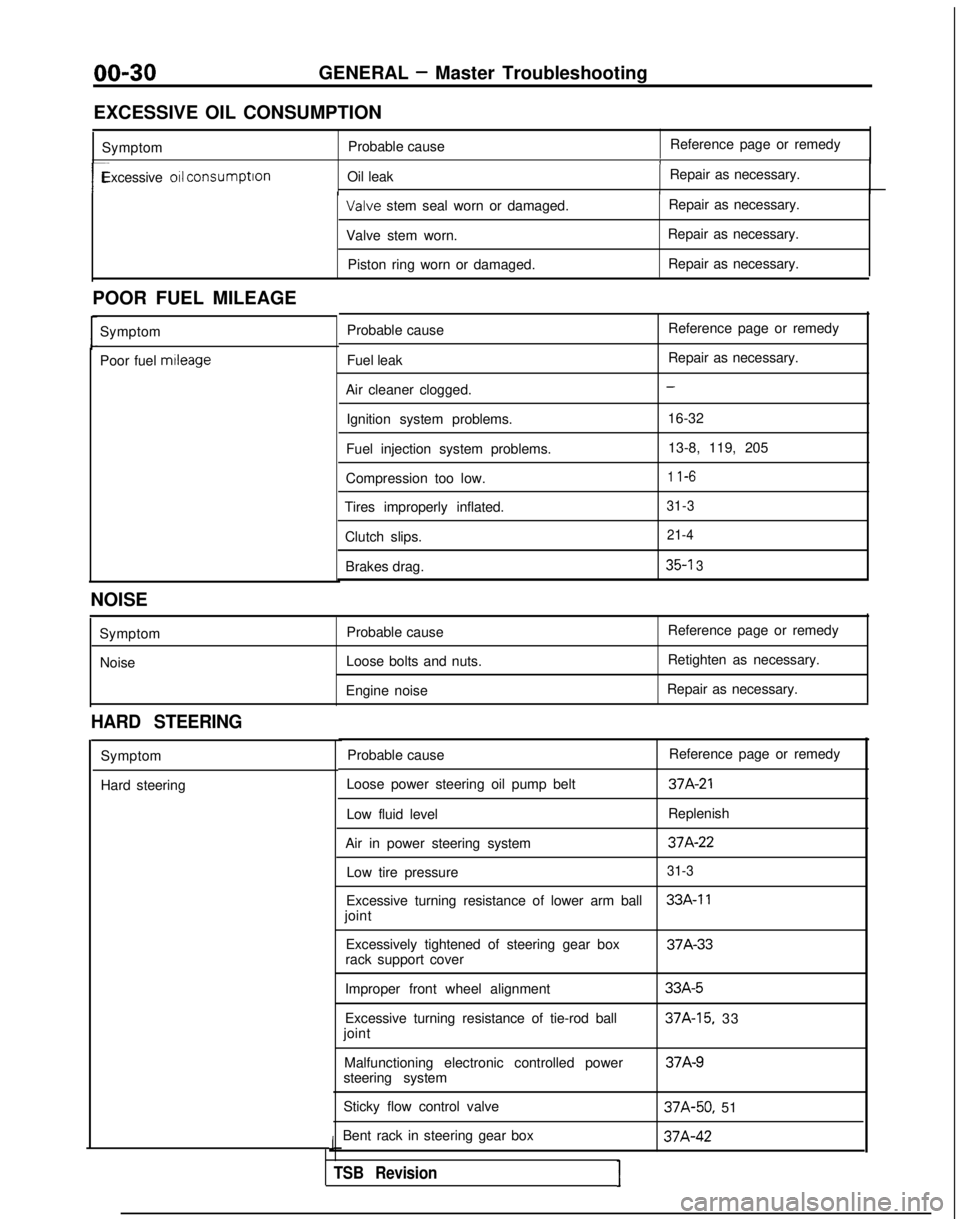
EXCESSIVE OIL CONSUMPTION Symptom Probable cause Reference page or remedy
1
r-Excessive 011 consumption
Oil leak Repair as necessary.I Valve
stem seal worn or damaged. Repair as necessary.
Valve stem worn. Repair as necessary.
Piston ring worn or damaged. Repair as necessary.
POOR FUEL MILEAGE Symptom
Poor fuel mtleage
Probable cause
Fuel leak
Air cleaner clogged. Ignition system problems.
Fuel injection system problems.
Compression too low.
Tires improperly inflated.
Clutch slips.Brakes drag. Reference page or remedy
Repair as necessary.
-
16-32
13-8, 119, 205
1 l-6
31-3 21-4
35-l 3
NOISE
SymptomNoise Probable cause
Loose bolts and nuts.
Engine noise Reference page or remedy
Retighten as necessary.
Repair as necessary.
HARD STEERING
Symptom
Hard steering Probable cause
Reference page or remedy
Loose power steering oil pump belt
37A-21
Low fluid level Replenish
Air in power steering system
37A-22
Low tire pressure31-3
Excessive turning resistance of lower arm ball33A-11
joint Excessively tightened of steering gear box 37A-33
rack support cover
Improper front wheel alignment
Excessive turning resistance of tie-rod ball
joint
Malfunctioning electronic controlled power
steering system
Sticky flow control valve
Bent rack in steering gear box
J
TSB RevisionI
33A-5
37A-15, 33 37A-9
37A-50,
51 37A-42
Page 37 of 1273
GENERAL -Lubrication and Maintenance/Recommended Lubricants and Lubricant Capacities Table00-35
If premium unleaded gasoltne IS not available,
MATERIALS ADDED TO FUEL
unleaded gasoline having a octane rating of 87 or
91 RON (Research Octane Number) may be used. Indiscriminate use of fuel system cleaning agents
In this case, the performance and fuel consumption should be avoided. Many of these materials
in-
WIII suffer a little degradatron.tended for gum and varnish removal may contain
highly active
solvents or similar ingredients that can
be harmful to gasket and diaphragm materials used
in fuel system component parts.
Gasolines containing alcohol
Some gasolrnes sold at service stations contain
alcohol, although they may not be SC identified. Use
of fuels containing alcohol is not recommended
unless the nature of the blend can be
determrned
as being satisfactory.
Gasohol
- A mixture of 10% ethanol (grain alcohol)
and 90% unleaded gasoline may be used
In your
car. If
driveability problems are experienced as a
result of using gasohol, it IS recommended that the
car be operated on gasoline. Methanol
- Do not use gasolines containing
methanol (wood alcohol). Use of this type of
alcohol can result in vehicle performance deteriora-
tion and damage critical parts in the fuel system
components. Fuel system damage and performance
problems, resulting from the use of gasolines
containing methanol, may not be covered by the
new car warranty.
Gasolines containing MTBE (Methyl Tertiary Butyl
Ether)
Unleaded gasolrne containrng
15% or less MTBE
may be used in your car. (Fuel containing MTBE
over 15% vol. may cause reduced engine per-
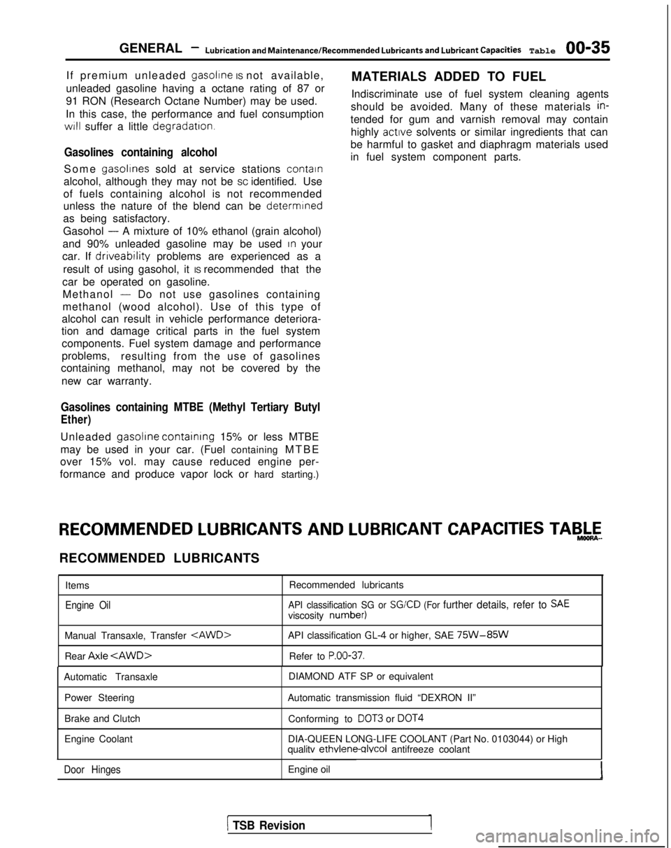
formance and produce vapor lock or hard starting.) RECOMMENDED
LUBRICANTS AND
LUBRICANT CAPACITIES TAB,&-
RECOMMENDED LUBRICANTS
Items
Engine Oil
Recommended lubricants
API classification SG or SGKD (For further details, refer to SAEviscosity number)
Manual Transaxle, Transfer
Rear Axle
API classification GL-4 or higher, SAE 75W-85W
Refer to P.OO-37.
Automatic Transaxle
Power Steering
Brake and Clutch
Engine Coolant DIAMOND ATF SP or equivalent
Automatic transmission fluid “DEXRON II” Conforming to
DOT3 or DOT4
DIA-QUEEN LONG-LIFE COOLANT (Part No. 0103044) or High
qualitv ethvlene-qlvcol
antifreeze coolant
Door HingesEngine oil
1 TSB Revision
Page 45 of 1273
GENERAL - Maintenance Service00-43
1
O.AUTOMATIC
TRANSAXLE
Inspect fluid levelMOOSSDA
1. Drive until the fluid temperature reaches the usual ternperature
[70-80°C (160- 18O”F)I.
2. Plaice vehicle on level floor.
3.Move selector lever sequentially to every position to fill
torque converter and hydraulic circuit with fluid, then place lever in “N” Neutral position. This operation is
necessary to be sure that fluid level check is accurate.
4. Before removing dipstick, wipe all dirt from area around
dipstick. Then take out the dipstick and check the
condition of the fluid.
The transaxle should be overhauled under the following
conditions.l If there is a “burning” odor.
l If the fluid color has become noticeably blacker.
l If there is a noticeably great amount of metal particles in the fluid.
5.Chleck to see if fluid level is in “HOT” range on dipstick.
If fluid level is low, add ATF until level reaches “HOT”
range.
LO\N fluid level can cause a variety of conditions
because it allows pump to take in air along with fluid. Air
trapped in hydraulic circuit forms bubbles which make
fluid spongy. Therefore, pressures will be erratic. Improper filling can also raise fluid level too high. When
transaxle has too much fluid, gears churn up foam and cause same conditions which occur with low fluid level,
resulting in accelerated deterioration of ATF.In either case, air bubbles can cause overheating, fluid
oxidation, which can interfere with normal valve, clutch,
and servo operation. Foaming can also result in fluid escaping from transaxle vent where it may be mistaken
for a leak.
6. Be sure to examine fluid on dipstick closely. Chaqge
fluid
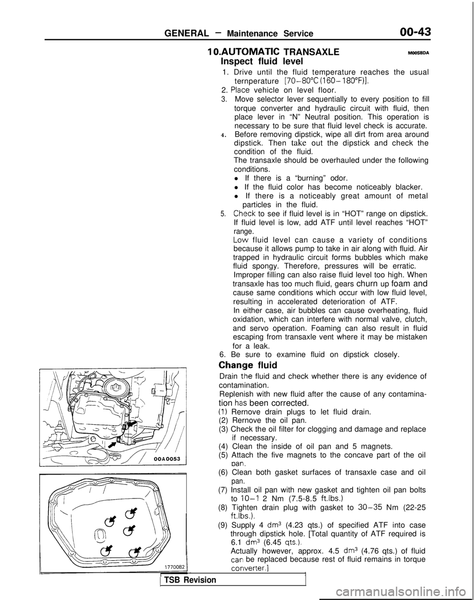
Drain
tlhe fluid and check whether there is any evidence of
contamination. Replenish with new fluid after the cause of any contamina-
tion
has been corrected.
(1) Rernove drain plugs to let fluid drain.
(2) Rernove the oil pan.
(3) Check the oil filter for clogging and damage and replace
if necessary.
(4) Clean the inside of oil pan and 5 magnets.
(5) Attach the five magnets to the concave part of the oil
pan.
1 TSB Revision
(6) Clean both gasket surfaces of transaxle case and oil
pan.
(7) Install oil pan with new gasket and tighten oil pan bolts
to
IO-I 2 Nm (7.5-8.5 ftlbs.)
(8) Tighten drain plug with gasket to 30-35 Nm (22-25 ft.lbs.).
(9) Supply 4
dm3 (4.23 qts.) of specified ATF into case
through dipstick hole. [Total quantity of ATF required is 6.1
dm3 (6.45 qts.).
Actually however, approx. 4.5 dm3 (4.76 qts.) of fluid
car1 be replaced because rest of fluid remains in torque converter.]
1
Page 143 of 1273
13-1
FUEL
CONTENTSM’ISAA--
AUTO-CRUISE CONTROL SYSTEM.............
.
332
AUTO-CRUISE CONTROL ............................. 408
SERVICE ADJUSTMENT PROCEDURES .................397
Accelerator Cables
inspectron and Adjustment ........
.
398 Auto-cruise
Control System Inspection
..............397
Individual Parts Inspection ......................
401SPECfAL
TOOLS
.....................................
333
SPECIFICATIONS .................................... 332
TROUBLESHOOTING ................................. 334
Auto-cruise Control Components Location ..........368
Auto-cruise Control
Related Harnesses
..........365
Check Chart
Check Chart
Circuit Diagram ................................
371input Checking................................
.
366
On-board Diagnostic Checking ......................
361Troubleshooting Quick-reference Chart
.
334
Troubleshooting Quick-reference Chart
ENGINE CONTROL...............................
.
328
ENGINE CONTROL ..................................
330
SERVICE ADJUSTMENT PROCEDURES .................329
Accelerator Cable inspectron and Adjustment
...........329
Accelerator Switch Inspection and Adjustment ..........329
SPECIFICATIONS ....................................
328
TROUBLESHOOTlNG................................
.
328
Accelerator
Cable and Accelerator Pedal .............
.
328
FUEL SYSTEM
FUEL FILTER .........................................
327
FUEL LINE AND VAPOR LINE
.
326
FUEL LINE AND VAPOR LINE
.
324
FUEL TANK
.
322
FUELTANK
.
318
GENERAL INFORMATION ............................ 196
ON-VEHICLE INSPECTION OF MFI
COMPONENTS
......251
Air Conditioning Switch and A/C Compressor Clutch Relay .....................................
285
Barometric Pressure Sensor .................... 266
Boost Meter
311Camshaft Position Sensor ........................
.
277Closed Throttle Position Switch
.....................
.
274
Component Location .............................
251Components Inspection Pocedure
................. 255
Crankshaft Position Sensor ..................... 280EGR
Solenord
...................
.
307EGR Temperature Sensor
.............
.
288Engrne Control Module Power Ground
................
.
257
Engine Coolant Temperature Sensor ..................
268Evaporative Emission Purge Solenoid .................
.
307
Fuel Pressure Solenoid
307Fuel Pressure Test...............................
.
312
Fuel Pump ...................................... 258
Heated Oxygen Sensor ............................ 290
Idle Air Control Motor (Stepper Motor) ................
238Ignition Coil and Ignition Power Transistor .............
.
302
Ignition Switch-ST .................................. 284
Ignition Switch-ST and Park/Neutral Position Switch .....284
Injectors .......................................
295Inspection of Engine Control Module Terminal
Voltage .......................................
.
315
Intake Air Temperature Sensor .......................263
Knock Sensor
Power Steering Pressure Switch ......................
284Power Supply and Ignition Switch ...................
.
255Resistor
..............................
.
298Terminal Voltage Check Chart
......................
.
315Throttle Position Sensor
..........................
.
270Turbocharger Waste Gate Solenoid
.........
.
309 Vehicle
Speed Sensor
............................... 284
Volume Air Flow Sensor ............................
261SERVICE ADJUSTMENT PROCEDURES ...............
.
245
Basic
idle Speed Adjustment .......................
.
245
Closed Throttle Position Switch (Fixed
SAS)Adjustment ......................................
.
250
Curb
Idle Speed Inspection
..........................245Throttle Body (Throttle Valve Area) Cleaning
...........
.
248Throttle Position Sensor Adjustment
..................
.
248
SPECIALTOOLS...................................
.
204
SPECIFICATIONS ...................................
201TROUBLESHOOTING ...............................
.
205
Check Engine/Malfunction Indicator Lamp ..............205
Circuit Diagram .................................... 214
Clear Memory of Diagnostic Trouble Code .............
211Explanation and Precaution Related to Harness
Checking ......................................
.
205Explanation of Troubleshooting Procedures
............
.
205Failsafe/Back-up Functions List
.....................
.
211Fuel tank and Fuel Line
............................
.
244
Read Out Diagnostic Trouble Code ...................
211Troubleshooting Table
.............................
.
208(CONTINUED ON NEXT PAGE)