1989 MITSUBISHI GALANT reset
[x] Cancel search: resetPage 62 of 1273
11-12ENGINE
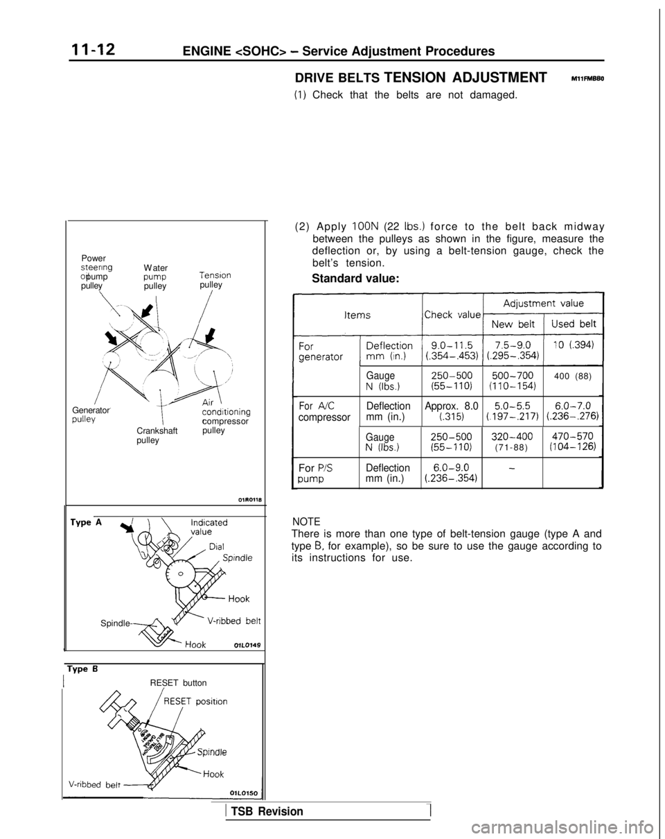
DRIVE BELTS TENSION ADJUSTMENT
MllFMBBO
(1) Check that the belts are not damaged.
Power steenng
oil pump
pulley
\
W
ater
pump
pulley
I Tension
pulley/
Generator
compressor
Crankshaft
pulley pulley
We
Spindle----As.
IRESET button (2) Apply
IOON (22 Ibs.) force to the belt back midwa
y
between the pulleys as shown in the figure, measure the
deflection or, by using a belt-tension gauge, check the
belt’s tension.
Standard value:
Gauge250-500500-700400 (88)
N (Ibs.)(55-110)(110-154)
ForAKDeflection Approx. 8.05.0-5.56.0-7.0
compressor mm (in.)(.315)(.197-,217) (.236-.276)
For P/S
pump Gauge
250-500320-400470-570
N (Ibs.)(55-110)(71-88)(104-126)
Deflection 6.0-9.0
-mm (in.)(.236-,354)
NOTE
There is more than one type of belt-tension gauge (type A and
type
8, for example), so be sure to use the gauge according to
its instructions for use.
1 TSB Revision
Page 99 of 1273
ENGINE
Crankshaft
sprocket “B”
/
Crankshaft/\ \sprocket Flange Crankshaft 6~~~72
Plain washer-J
26
@
Plug
6EN0281
I
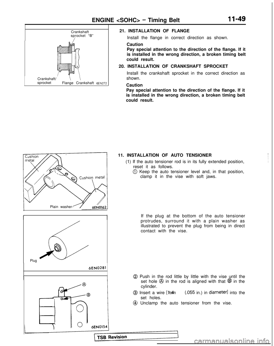
21. INSTALLATION OF FLANGE
Install the flange in correct direction as shown.
Caution Pay special attention to the direction of the flange. If it
is installed in the wrong direction, a broken timing belt
could result.
20. INSTALLATION OF CRANKSHAFT SPROCKET Install the crankshaft sprocket in the correct direction as
shown.
Caution
Pay special attention to the direction of the flange. If it
is installed in the wrong direction, a broken timing belt
could result.
11. INSTALLATION OF AUTO TENSIONER (1) If the auto tensioner rod is in its fully extended position,reset it as follows.
@ Keep the auto tensioner level and, in that position,clamp it in the vise with soft jaws.
If the plug at the bottom of the auto tensioner
protrudes, surround it with a plain washer as illustrated to prevent the plug from being in direct
contact with the vise.
@ Push in the rod little by little with the vise until the set hole
@ in the rod is aligned with that @ in the
cylinder.
@ Insert a wire [1.4 mm (055 in.) in diameter]
into the
set holes.
@ Unclamp the auto tensioner from the vise.
Page 111 of 1273
ENGINE
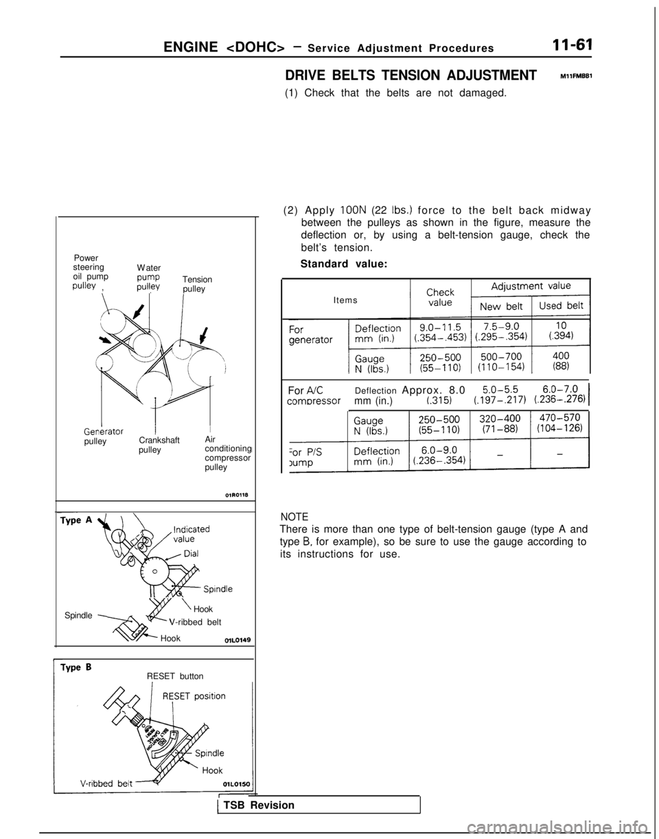
DRIVE BELTS TENSION ADJUSTMENT
MllFMBBl
(1) Check that the belts are not damaged.
Power
steering
oil pump
pulley , W
ater
pump
pulley
Tension
pulley
f /
xI J
b
L ‘d
p1 Genkrator
I
Ipulley
Crankshaft
Air
pulley conditioning
compressor
pulley
Spindle Spindle
2Y
\Hook
xi@--
V-ribbed belt
Hook
r
Type BRESET button (2) Apply
100N (22 Ibs.) force to the belt back midwa
y
between the pulleys as shown in the figure, measure the
deflection or, by using a belt-tension gauge, check the
belt’s tension.
Standard value:
Items
For
AKDeflection Approx. 8.05.0-5.56.0-7.0
comDressormm (in.)t.3151(.197-,217) (.236-.276)I
NOTE
There is more than one type of belt-tension gauge (type A and
type
B, for example), so be sure to use the gauge according to
its instructions for use.
1 TSB Revision
Page 138 of 1273
ENGINE
6
@
Plug
6EN0281
Center bolt :
6EN026:-
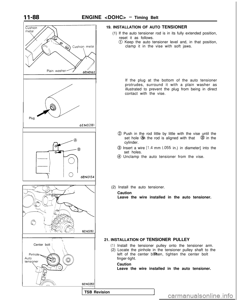
19. INSTALLATION OF AUTO TENSIONER
(1) If the auto tensioner rod is in its fully extended position, reset it as follows.
@I Keep the auto tensioner level and, in that position,clamp it in the vise with soft jaws.
If the plug at the bottom of the auto tensioner
protrudes, surround it with a plain washer as illustrated to prevent the plug from being in direct
contact with the vise.
@ Push in the rod little by little with the vise until the set hole @ in the rod is aligned with that
@I in the
cylinder.
@ Insert a wire Il.4 mm (055 in.) in diameter] into the
set holes.
@I Unclamp the auto tensioner from the vise.
(2) Install the auto tensioner. CautionLeave the wire installed in the auto tensioner.
21. INSTALLATION OF TENSIONER PULLEY
(1) Install the tensioner pulley onto the tensioner arm.
(2) Locate the pinhole in the tensioner pulley shaft to the left of the center bolt. Then, tighten the center bolt
finger-tight.
Caution
Leave the wire installed in the auto tensioner.
TSB Revision
I
Page 158 of 1273
13-16
FUEL SYSTEM
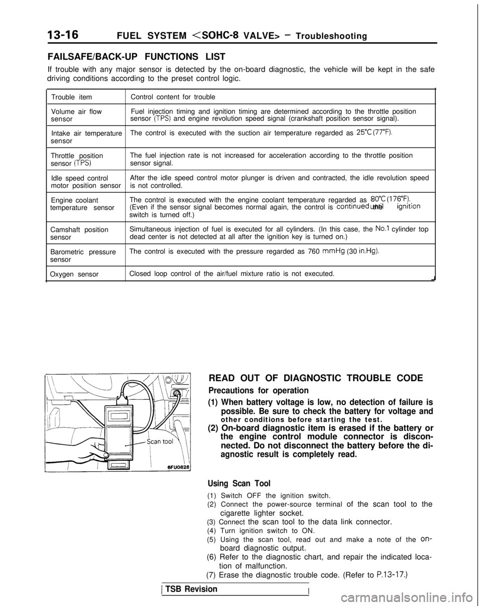
FAILSAFE/BACK-UP FUNCTIONS LIST
If trouble with any major sensor is detected by the on-board diagnostic,\
the vehicle will be kept in the safe
driving conditions according to the preset control logic.
Trouble item Control content for trouble
Volume air flow Fuel injection timing and ignition timing are determined according to th\
e throttle position
sensor sensor
(TPS) and engine revolution speed signal (crankshaft position sensor signal)\
.
Intake air temperature The control is executed with the suction air temperature regarded as
25°C (77°F).
sensor
Throttle position The fuel injection rate is not increased for acceleration according to t\
he throttle position
sensor
(TPS)sensor signal.
Idle speed control After the idle speed control motor plunger is driven and contracted, the\
idle revolution speed
motor position sensor is not controlled.
Engine coolant The control is executed with the engine coolant temperature regarded as \
8OO.C (176°F).temperature sensor (Even if the sensor signal becomes normal again, the control is continued
until the ignltlon
switch is turned off.)
Camshaft position Simultaneous injection of fuel is executed for all cylinders. (In this \
case, the
No.1 cylinder top
sensor dead center is not detected at all after the ignition key is turned on.)\
Barometric pressure The control is executed with the pressure regarded as 760 mmHg
(30
in.Hg).
sensor
Oxygen sensor Closed loop control of the air/fuel mixture ratio is not executed.
i
READ OUT OF DIAGNOSTIC TROUBLE CODE
Precautions for operation
(1) When battery voltage is low, no detection of failure is possible. Be sure to check the battery for voltage and
other conditions before starting the test.
(2) On-board diagnostic item is erased if the battery or the engine control module connector is discon-
nected. Do not disconnect the battery before the di-
agnostic result is completely read.
Using Scan Tool
(1) Switch OFF the ignition switch.
(2) Connect the power-source terminal of the scan tool to the
cigarette lighter socket.
(3) Connect the scan tool to the data link connector. (4) Turn ignition switch to ON.
(5) Using the scan tool, read out and make a note of the
on-
board diagnostic output.
(6) Refer to the diagnostic chart, and repair the indicated loca-
tion of malfunction.
(7) Erase the diagnostic trouble code. (Refer to
P.13-17.)
1 TSB RevisionI
Page 268 of 1273
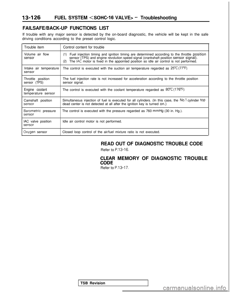
13-126FUEL SYSTEM
FAILSAFE/BACK-UP FUNCTIONS LIST
If trouble with any major sensor is detected by the on-board diagnostic,\
the vehicle will be kept in the safe
driving conditions according to the preset control logic.
Trouble item Control content for trouble
Volume air flow(1)Fuel injection timing and ignition timing are determined according to th\
e throttle positionsensorsensor (TPS) and engine revolution speed signal (crankshaft position \
sensor signal).(2)The IAC motor is fixed in the appointed position so idle air control is not per\
formed.
Intake air temperature The control is executed with the suction air temperature regarded as
25°C (77°F).sensor
Throttle position The fuel injection rate is not increased for acceleration according to t\
he throttle position
sensor (TPS)sensor signal.
Engine coolantThe control is executed with the coolant temperature regarded as 80°C (176’F).temperature sensor
Camshaft positionSimultaneous injection of fuel is executed for all cylinders. (In this \
case, the
No.1 cylinder top
jenS0r
dead center is not detected at all after the ignition key is turned
on.)3arometric
pressure The control is executed with the pressure regarded as 760 mmHg
(30 in. Hg.).
sensor
AC valve position Idle air control motor is not performed.;ensor
Ixygen sensor
Closed loop control of the air/fuel mixture ratio is not executed.
READ OUT OF DIAGNOSTIC TROUBLE CODE
Refer to P.13-16.
EbW&R MEMORY OF DIAGNOSTIC TROUBLE
Refer to
P.13-17.
TSB Revision
Page 335 of 1273
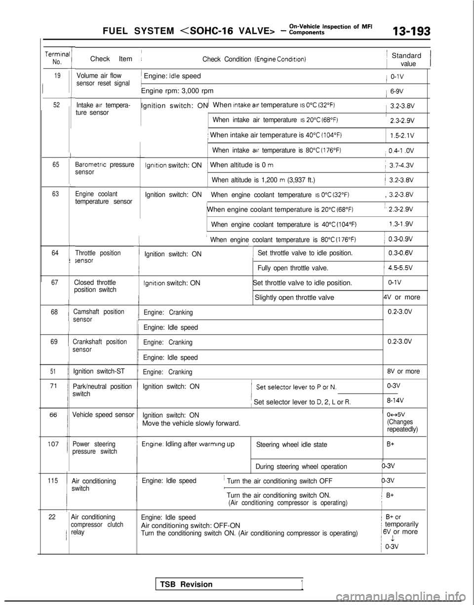
FUEL SYSTEM
TerminaNo.
19
52
-rII
i
t
c
65
L
63
64t
I:
I
Check Item :Check Condition (Engrne Condrtron)
Volume air flowj Engine: Idle speedsensor reset signal
1
Engine rpm: 3,000 rpm
Intake air tempera-1Ignition switch: ON When Intake atr temperature IS 0°C (32°F)ture sensor
When intake air temperature IS 20°C (68°F)
i When intake air temperature is 40°C (104°F)
When intake air temperature is 80°C (176°F)
lgnltlon switch: ON’ When altitude is 0 m
When altitude is 1,200 m (3,937 ft.)
Ignition switch: ON
i When engine coolant temperature IS 0°C (32°F)
When engine coolant temperature is 20°C (68°F)
When engine coolant temperature is 40°C (104°F)
Barometnc pressuresensor
Engine coolant
temperature sensor
Throttle positionsensor
67
68
69
51
115
1
1
Ic22
Closed throttle
position switch
Camshaft position
sensor
Crankshaft position
sensor
Ignition switch-ST
Park/neutral position
switch
Vehicle speed sensor
Power steering
pressure switch
Air conditioning
switch
-I
I When engine coolant temperature is 80°C (176°F)
‘I
) 0.3-0.9v
Ignition switch: ON Set throttle valve to idle position.
0.3-0.6V
iFully open throttle valve.1 4.5-5.5v
Ignition switch: ON
Set throttle valve to idle position.o-1v
’ Slightly open throttle valve4V or more
Engine: Cranking0.2-3.OV
Engine: Idle speed
Engine: Cranking0.2-3.OV
Engine: Idle speed
Engine: Cranking8V or more
Ignition switch: ON
( SetselectorlevertoPorN.o-3v
i Set selector lever to D. 2, L or R.8-14V
Ignition switch: ONi 04d5v
Move the vehicle slowly forward.(Changesrepeatedly)
Engine. Idling after warmrng upSteering wheel idle stateB+
During steering wheel operationo-3v
Engine: Idle speed
’ Turn the air conditioning switch OFFo-3vI
’ Turn the air conditioning switch ON.1 B+(Air conditioning compressor is operating)!
Engine: Idle speed1 B+or
Air conditioning switch: OFF-ONI temporarily
Turn the conditioning switch ON. (Air conditioning compressor is operat\
ing) 1
6V or morej 1
1 o-3v
/ Standard
value
/ o-1v
1 6-9V
1 3.2-3.8V
: 2.3-2.9v
1.5-2.1V
i 0.4-I .ov
j 3.7-4.3v
/ 3.2-3.8V
, 3.2-3.8V
1, 2.3-2.9v
1.3-l .9vI
Air conditioningcompressor clutchrelay
TSB Revision1
Page 353 of 1273
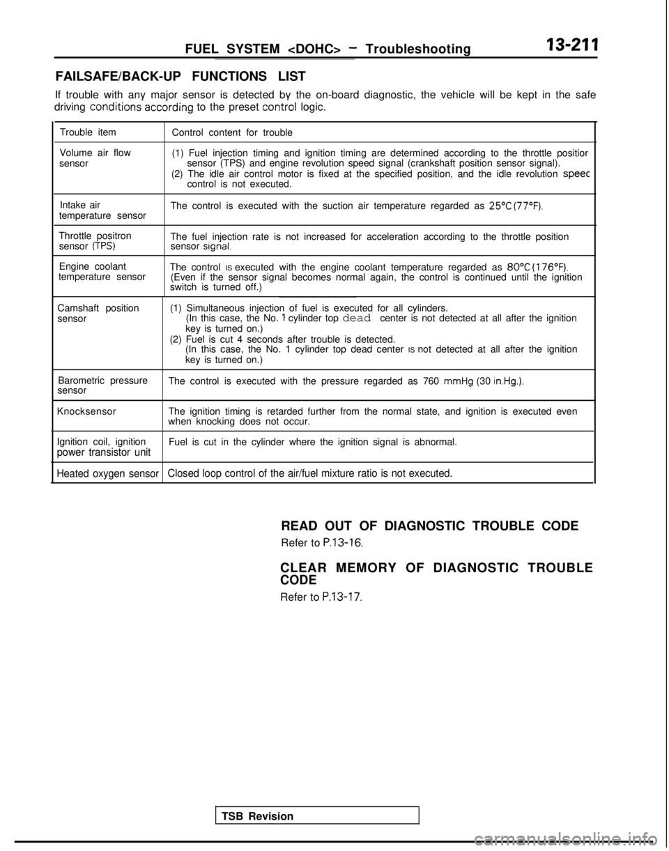
FUEL SYSTEM
FAILSAFE/BACK-UP FUNCTIONS LIST
If trouble with any major sensor is detected by the on-board diagnostic,\
the vehicle will be kept in the safe
driving conditions-accdrding
to the preset control
logic.
Trouble item
Volume air flow
sensor Control content for trouble
(1) Fuel injection timing and ignition timing are determined according\
to the throttle positior
sensor (TPS) and engine revolution speed signal (crankshaft position \
sensor signal).
(2) The idle air control motor is fixed at the specified position, and\
the idle revolution speec
control is not executed.
Intake air
temperature sensor The control is executed with the suction air temperature regarded as
25’C (77°F).
Throttle positron
sensor (TPS)The fuel injection rate is not increased for acceleration according to t\
he throttle positionsensor signal.
Engine coolant
temperature sensor The control IS executed with the engine coolant temperature regarded as 80°C
(176°F).(Even if the sensor signal becomes normal again, the control is continu\
ed until the ignition
switch is turned off.)
Camshaft position
sensor (1) Simultaneous injection of fuel is executed for all cylinders.
(In this case, the No.
1 cylinder top dead center is not detected at all after the ignition
key is turned on.)
(2) Fuel is cut 4 seconds after trouble is detected. (In this case, the No. 1 cylinder top dead center IS not detected at all after the ignition
key is turned on.)
Barometric pressure
sensor The control is executed with the pressure regarded as 760
mmHg (30 in.Hg.).
Knocksensor
The ignition timing is retarded further from the normal state, and ignit\
ion is executed even
when knocking does not occur.
Ignition coil, ignition
power transistor unitFuel is cut in the cylinder where the ignition signal is abnormal.
Heated oxygen sensor Closed loop control of the air/fuel mixture ratio is not executed.
TSB RevisionREAD OUT OF DIAGNOSTIC TROUBLE CODE
Refer to
P.13-16.
CLEAR MEMORY OF DIAGNOSTIC TROUBLE
CODE
Refer to P.13-17.