1989 MITSUBISHI GALANT oil
[x] Cancel search: oilPage 3 of 1273
00-l
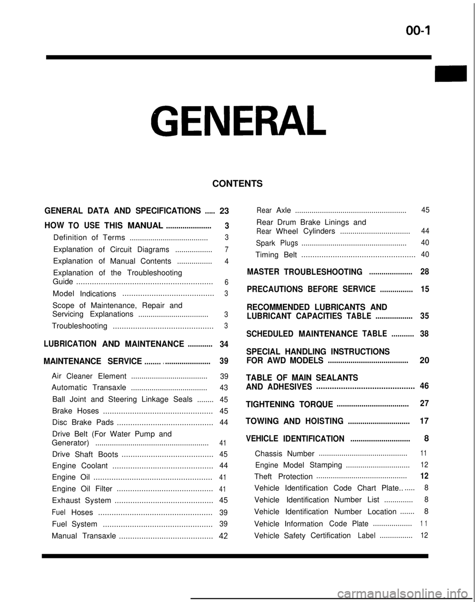
GENERAL
CONTENTS
GENERAL DATA AND SPECIFICATIONS.....23
HOWTOUSETHISMANUAL......................
3
Definition of Terms ......................................3
ExplanationofCircuitDiagrams..................7
Explanation of
ManualContents .................4
Explanation of the Troubleshooting
Guide .............................................................
6
Model
Indications .........................................3
Scope of Maintenance, Repair and
Servicing Explanations
..................................
3
Troubleshooting .............................................3
LUBRICATIONANDMAINTENANCE............
34
MAINTENANCE SERVICE............................... 39
AirCleanerElement
.....................................39
Automatic
Transaxle
.....................................43
Ball Joint and Steering Linkage Seals ........45
Brake Hoses................................................. 45
Disc Brake Pads ........................................... 44
Drive Belt (For Water Pump and
Generator) .......................................................
41
Drive
Shaft Boots .........................................45
Engine Coolant
............................................. 44
Engine Oil .....................................................
41
Engine Oil Filter ...........................................41
Exhaust System
............................................ 45
FuelHoses
...................................................39
Fuel System
.................................................39
Manual Transaxle ..........................................42
RearAxle......................................................45
Rear Drum Brake Linings and
RearWheel Cylinders
..................................44
Spark
Plugs...................................................40
Timing Belt...................................................40
MASTER
TROUBLESHOOTING.....................28
PRECAUTIONS
BEFORESERVICE................15
RECOMMENDED LUBRICANTS AND
LUBRICANT CAPACITIESTABLE..................35
SCHEDULED
MAINTENANCETABLE ...........38
SPECIAL HANDLING INSTRUCTIONS
FOR AWD MODELS
.......................................20
TABLE OF MAIN SEALANTS
AND
ADHESIVES ............................................46
TIGHTENING TORQUE
................................... 27
TOWING
ANDHOISTING ..............................17
VEHICLE
IDENTIFICATION .............................8
Chassis Number ...........................................
11
EngineModel
Stamping
...............................12
Theft Protection ............................................12
Vehicle Identification Code Chart Plate.......
8
Vehicle Identification Number List
..............8
Vehicle Identification Number Location .......
8
Vehicle Information
CodePlate...................1 1
Vehicle SafetyCertificationLabel................12
Page 6 of 1273
00-4GENERAL - How to Use This Manual
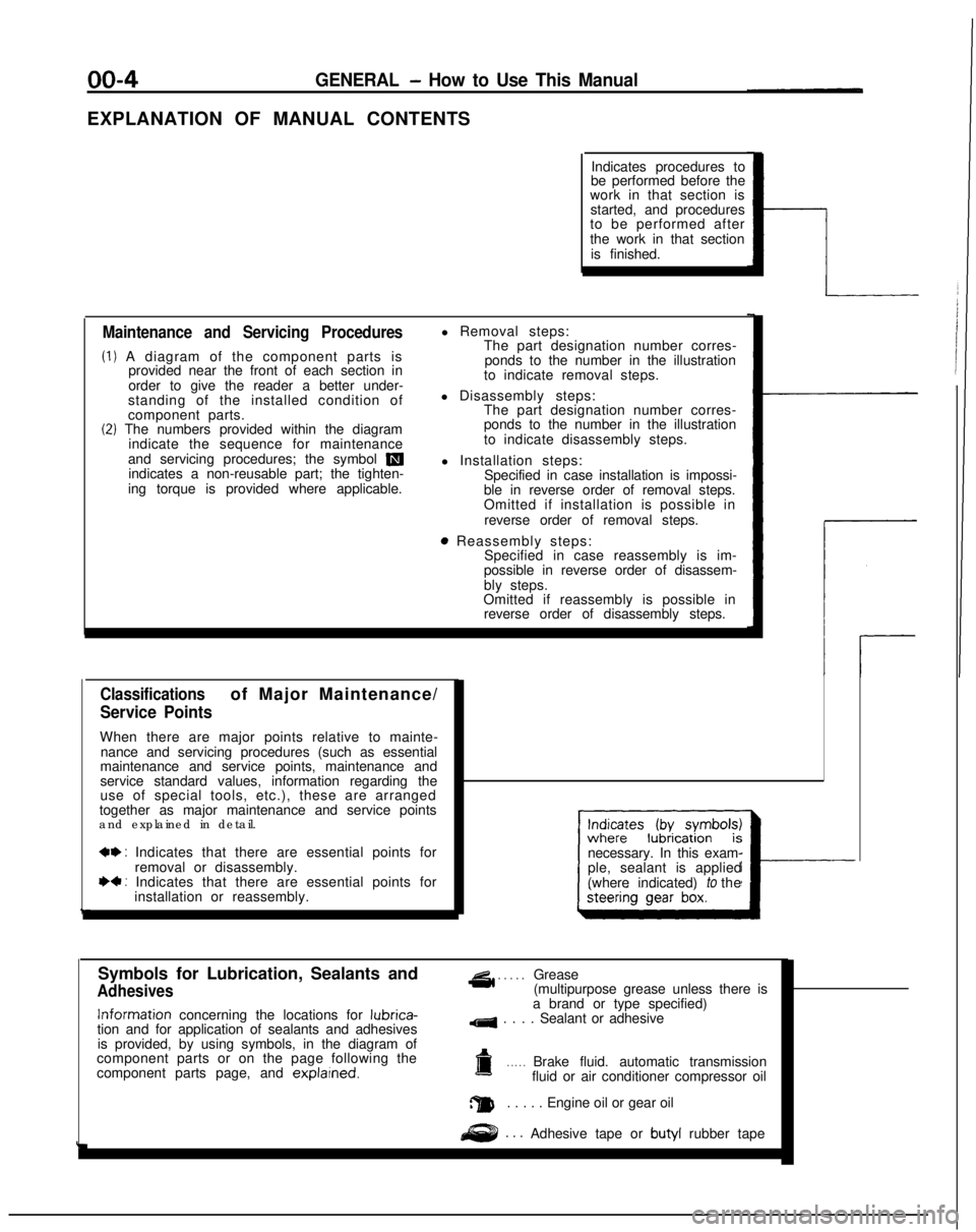
EXPLANATION OF MANUAL CONTENTSIndicates procedures to
be performed before the
work in that section is
started, and procedures
to be performed after
the work in that section
is finished.
Maintenance and Servicing Procedures
(1) A diagram of the component parts is provided near the front of each section in
order to give the reader a better under-
standing of the installed condition of
component parts.
(2) The numbers provided within the diagram indicate the sequence for maintenance
and servicing procedures; the symbol
mindicates a non-reusable part; the tighten-
ing torque is provided where applicable. l Removal steps:
The part designation number corres-
ponds to the number in the illustration
to indicate removal steps.
l Disassembly steps: The part designation number corres-
ponds to the number in the illustration
to indicate disassembly steps.
l Installation steps: Specified in case installation is impossi-
ble in reverse order of removal steps.
Omitted if installation is possible in
reverse order of removal steps.
8 Reassembly steps: Specified in case reassembly is im-
possible in reverse order of disassem-
bly steps.
Omitted if reassembly is possible in reverse order of disassembly steps.
Classificationsof Major Maintenance/
Service Points
When there are major points relative to mainte-
nance and servicing procedures (such as essential
maintenance and service points, maintenance and
service standard values, information regarding the
use of special tools, etc.), these are arranged
together as major maintenance and service points
and explained in detail.
*+ : Indicates that there are essential points for
removal or disassembly.
I)+ : Indicates that there are essential points forinstallation or reassembly. necessary. In this exam-
ple, sealant is applied
(where indicated) to the
I---
Symbols for Lubrication, Sealants and
Adhesives
4 . . . . .Grease
(multipurpose grease unless there is Information
concerning the locations for lubrica-
tion and for application of sealants and adhesives
is provided, by using symbols, in the diagram of
component parts or on the page following the
component parts page, and explarned.
a brand or type specified)
4 . . . . Sealant or adhesive
a. . . . .Brake fluid. automatic transmission
fluid or air conditioner compressor oil
a. . . . . Engine oil or gear oil
. . .Adhesive tape or butyl
rubber tape
Page 7 of 1273
GENERAL - How to Use This Manual
QfitIIICQ CTEEQINC CFAR RnY..^-TV..&” Y.LLI.II.Y Y_.. w-1.
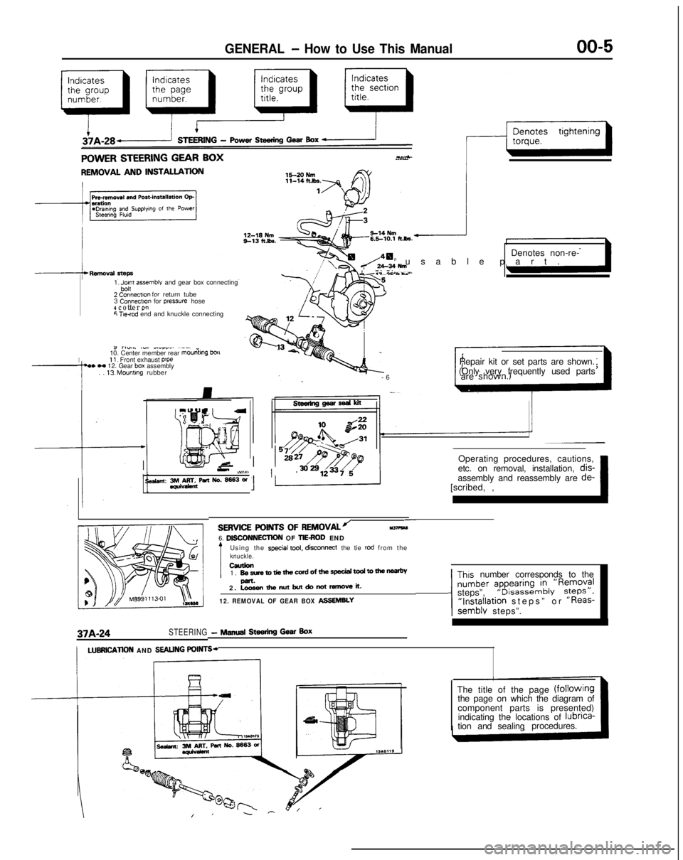
REMOVAL AND INSTALLATION
1, Jpn assemble and gear box connecting
2 Connectlo” for return tube
3 Connectm
for pressure hose4 cotter P!”6 T!e-rod end and knuckle connecting
I
J rl”.#l ~“,. dLlrr_. ..__
10. Center member rear mouniing
bou11, Front exhaust p’pe4. H 12. Gear box assembly
. . 13. Mounting rubber Denotes non-re-
p usable part
.
Y.T-*c As..
-
6
Repair kit or set parts are shown.
(Only very frequently used parts
Operating procedures, cautions,
II-’ iY,W11 ’etc. on removal, installation, dis-
se&an: 3rM&rr&paNo.~3W[scribed, ,~ 1assembly and reassembly are
de-
37A-24STEERING- NINA Steering Gear Box
-SERVICE POINTS OF
REMOVALJll37?kM6. DlSCONNECllON OF TIEROD END
Using the special tool, disconnect
the tie rod from theknuckle.ceurion1. BesretotiethewrdofthespeciaitodtomenP-.2. Loosenthenutbutdonotremoveit.
12. REMOVAL OF GEAR BOX ASSEMBLY
Thus number corresponds to the
number ?pyi:,“~&‘R~;;?Isteps”,“Installation steps” or “Reas-semblv steps”.
/LUBRlCATlON AND SEALING POINTS-
The title of the page (fOilOWingthe page on which the diagram of
component parts is presented)
indicating the locations of lubnca-
tion and sealingprocedures.
Page 22 of 1273
00-20GENERAL - Special Handling Instructions for AWD Models
SPECIAL HANDLING INSTRUCTIONS
FOR AWD MODELS
TOWIN
G
MomMA
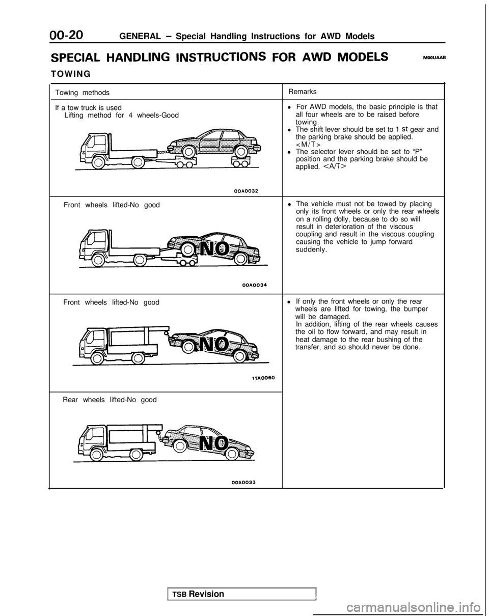
Towing methods
If a tow truck is used Lifting method for 4 wheels-Good Remarks
l For AWD models, the basic principle is that
all four wheels are to be raised before
towing.
l The shift lever should be set to 1
st gear and
the parking brake should be applied.
l The selector lever should be set to “P” position and the parking brake should be
applied.
OOA0032
Front wheels lifted-No good l The vehicle must not be towed by placing
only its front wheels or only the rear wheels
on a rolling dolly, because to do so willresult in deterioration of the viscous
coupling and result in the viscous coupling
causing the vehicle to jump forward
suddenly.
OOA0034
Front wheels lifted-No good l
If only the front wheels or only the rear
wheels are lifted for towing, the bumper
will be damaged. In addition, lifting of the rear wheels causes
the oil to flow forward, and may result in
heat damage to the rear bushing of the
transfer, and so should never be done.
Rear wheels lifted-No good
OOA0033
TSB Revision1
Page 32 of 1273
00-30GENERAL - Master Troubleshooting
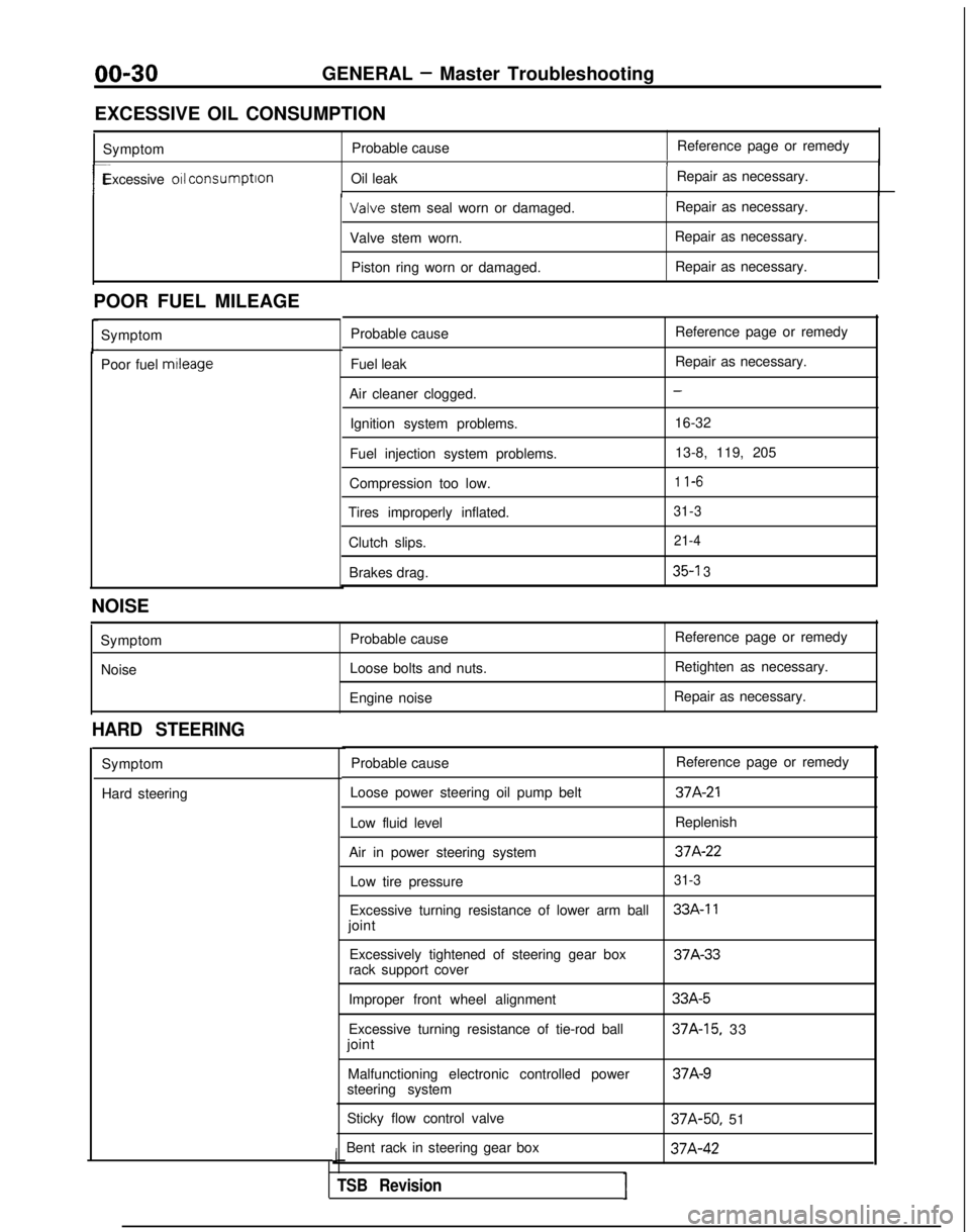
EXCESSIVE OIL CONSUMPTION Symptom Probable cause Reference page or remedy
1
r-Excessive 011 consumption
Oil leak Repair as necessary.I Valve
stem seal worn or damaged. Repair as necessary.
Valve stem worn. Repair as necessary.
Piston ring worn or damaged. Repair as necessary.
POOR FUEL MILEAGE Symptom
Poor fuel mtleage
Probable cause
Fuel leak
Air cleaner clogged. Ignition system problems.
Fuel injection system problems.
Compression too low.
Tires improperly inflated.
Clutch slips.Brakes drag. Reference page or remedy
Repair as necessary.
-
16-32
13-8, 119, 205
1 l-6
31-3 21-4
35-l 3
NOISE
SymptomNoise Probable cause
Loose bolts and nuts.
Engine noise Reference page or remedy
Retighten as necessary.
Repair as necessary.
HARD STEERING
Symptom
Hard steering Probable cause
Reference page or remedy
Loose power steering oil pump belt
37A-21
Low fluid level Replenish
Air in power steering system
37A-22
Low tire pressure31-3
Excessive turning resistance of lower arm ball33A-11
joint Excessively tightened of steering gear box 37A-33
rack support cover
Improper front wheel alignment
Excessive turning resistance of tie-rod ball
joint
Malfunctioning electronic controlled power
steering system
Sticky flow control valve
Bent rack in steering gear box
J
TSB RevisionI
33A-5
37A-15, 33 37A-9
37A-50,
51 37A-42
Page 33 of 1273
GENERAL - Master Troubleshooting
00-31
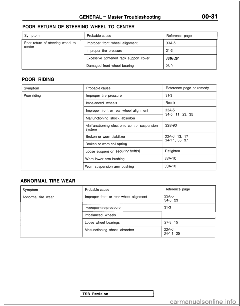
POOR RETURN OF STEERING WHEEL TO CENTER
Symptom
Probable cause Reference page
’Poor return of steering wheel to
Improper front wheel alignment33A-5center
Improper tire pressure31-3
Excessive tightened rack support cover 37A-35, 36, 37
Damaged front wheel bearing
26-9
POOR RIDING
Symptom
Poor riding Probable cause
Reference page or remedy
Improper tire pressure
31-3
lmbalanced wheelsRepair
Improper front or rear wheel alignment33A-5
34-5, 11, 23, 35
Malfunctioning shock absorber Malfunctioning
electronic control suspension
33B-90system
Broken or worn stabilizer
33A-6. 13, 1734-l 1, 35, 37
Broken or worn coil spri#ng
Loose suspension secuiring bolt(s)
Retighten
Worn lower arm bushing
33A-10
Worn suspension arm bushing 33A-IO
TSB Revision
ABNORMAL TIRE WEAR
Symptom
Abnormal tire wear Probable cause
Improper front or rear wheel alignment Reference page
33A-534-5, 23
131-3
lmbalanced wheelsII
Loose wheel bearings
27-3, 15
Malfunctioning shock absorber
33A-634-l 1, 35
Page 34 of 1273
00-32
GENERAL - Master Troubleshooting
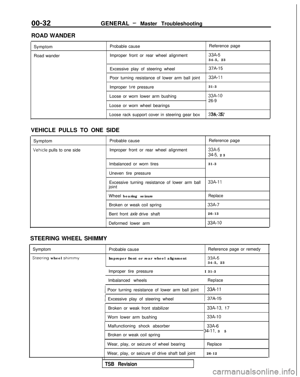
ROAD WANDER Symptom
Road wander Probable cause
Improper front or rear wheel alignment Reference page
33A-534-5, 23
Excessive play of steering wheel
37A-15
Poor turning resistance of lower arm ball joint33A-11
Improper tire pressure 31-3
Loose or worn lower arm bushing
33A-10
26-9
Loose or worn wheel bearings
Loose rack support cover in steering gear box 37A-35. 36, 37
VEHICLE PULLS TO ONE SIDE Symptom Probable cause Reference page
Vehrcle pulls to one side
Improper front or rear wheel alignment33A-5
34-5. 2
3
lmbalanced or worn tires 31-3
Uneven tire pressure Excessive turning resistance of lower arm ball
33A-17joint
Wheel bearing seizure
Replace
Broken or weak coil spring33A-7
Bent front axle drive shaft 26-13
Deformed lower arm
33A-10
STEERING WHEEL SHIMMY
Symptom
Steerlng wheel shlmmy
Probable cause
Improper front or rear wheel alignment Reference page or remedy
33A-534-5, 23
Improper tire pressure I 31-3
lmbalanced wheels
Replace
1 Poor turning resistance of lower arm ball joint) 33A-11
] Excessive play of steering wheel) 37A-15
Broken or weak front stabilizer
Worn lower arm bushing33A-13. 17
33A-10
Malfunctioning shock absorber
Broken or weak coil spring
Wear, play, or seizure of wheel bearing33A-6
34-11, 3
5
Replace
Wear, play, or seizure of drive shaft ball joint
26-12
TSB Revision1
Page 35 of 1273
GENERAL - Master Troubleshootinn
00-33
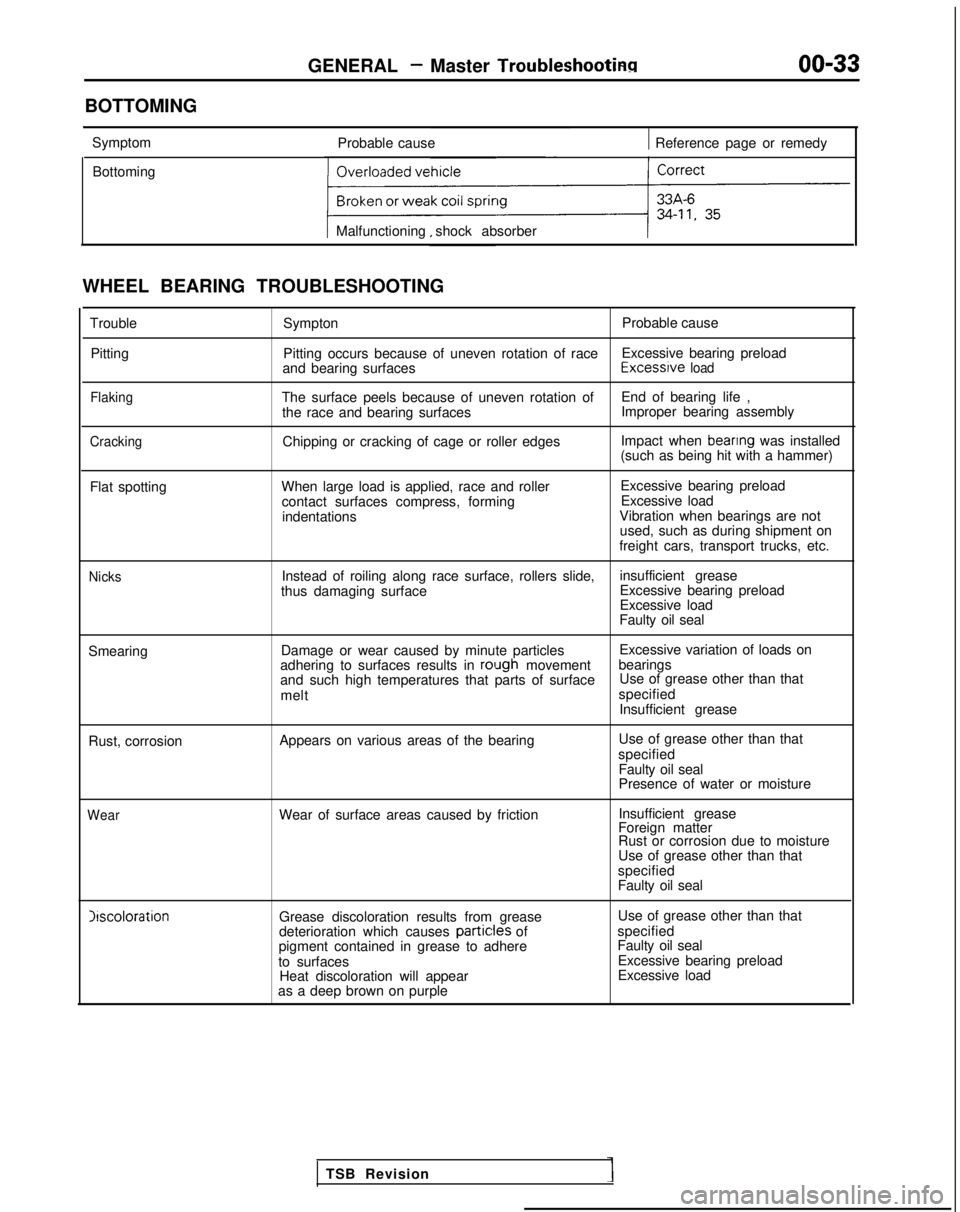
BOTTOMING Symptom Probable cause
1 Reference page or remedy
Bottoming
Malfunctioning shock absorber
WHEEL BEARING TROUBLESHOOTING TroublePitting
Flaking
Cracking
Sympton Probable cause
Pitting occurs because of uneven rotation of race Excessive bearing preload
and bearing surfaces Excessrve
load
The surface peels because of uneven rotation of
End of bearing life ,
the race and bearing surfaces Improper bearing assembly
Chipping or cracking of cage or roller edges Impact when
beanng was installed
(such as being hit with a hammer)
Flat spotting When large load is applied, race and roller
contact surfaces compress, formingindentations Excessive bearing preload
Excessive load
Vibration when bearings are not used, such as during shipment on
freight cars, transport trucks, etc.
NicksInstead of roiling along race surface, rollers slide, insufficient grease
thus damaging surface Excessive bearing preload
Excessive load
Faulty oil seal
Smearing Damage or wear caused by minute particles Excessive variation of loads on
adhering to surfaces results in
rolugh movement bearings
and such high temperatures that parts of surface Use of grease other than that
melt specified
Insufficient grease
Rust, corrosion Appears on various areas of the bearing Use of grease other than that
specified Faulty oil seal
Presence of water or moisture
WearWear of surface areas caused by friction Insufficient grease
Foreign matter
Rust or corrosion due to moisture
Use of grease other than that
specified
Faulty oil seal Irscoloration
Grease discoloration results from grease
deterioration which causes partic:les
of
pigment contained in grease to adhere
to surfaces Heat discoloration will appear
as a deep brown on purple Use of grease other than that
specified
Faulty oil seal Excessive bearing preload
Excessive load
TSB Revision