1989 MITSUBISHI GALANT oil
[x] Cancel search: oilPage 45 of 1273
GENERAL - Maintenance Service00-43
1
O.AUTOMATIC
TRANSAXLE
Inspect fluid levelMOOSSDA
1. Drive until the fluid temperature reaches the usual ternperature
[70-80°C (160- 18O”F)I.
2. Plaice vehicle on level floor.
3.Move selector lever sequentially to every position to fill
torque converter and hydraulic circuit with fluid, then place lever in “N” Neutral position. This operation is
necessary to be sure that fluid level check is accurate.
4. Before removing dipstick, wipe all dirt from area around
dipstick. Then take out the dipstick and check the
condition of the fluid.
The transaxle should be overhauled under the following
conditions.l If there is a “burning” odor.
l If the fluid color has become noticeably blacker.
l If there is a noticeably great amount of metal particles in the fluid.
5.Chleck to see if fluid level is in “HOT” range on dipstick.
If fluid level is low, add ATF until level reaches “HOT”
range.
LO\N fluid level can cause a variety of conditions
because it allows pump to take in air along with fluid. Air
trapped in hydraulic circuit forms bubbles which make
fluid spongy. Therefore, pressures will be erratic. Improper filling can also raise fluid level too high. When
transaxle has too much fluid, gears churn up foam and cause same conditions which occur with low fluid level,
resulting in accelerated deterioration of ATF.In either case, air bubbles can cause overheating, fluid
oxidation, which can interfere with normal valve, clutch,
and servo operation. Foaming can also result in fluid escaping from transaxle vent where it may be mistaken
for a leak.
6. Be sure to examine fluid on dipstick closely. Chaqge
fluid
Drain
tlhe fluid and check whether there is any evidence of
contamination. Replenish with new fluid after the cause of any contamina-
tion
has been corrected.
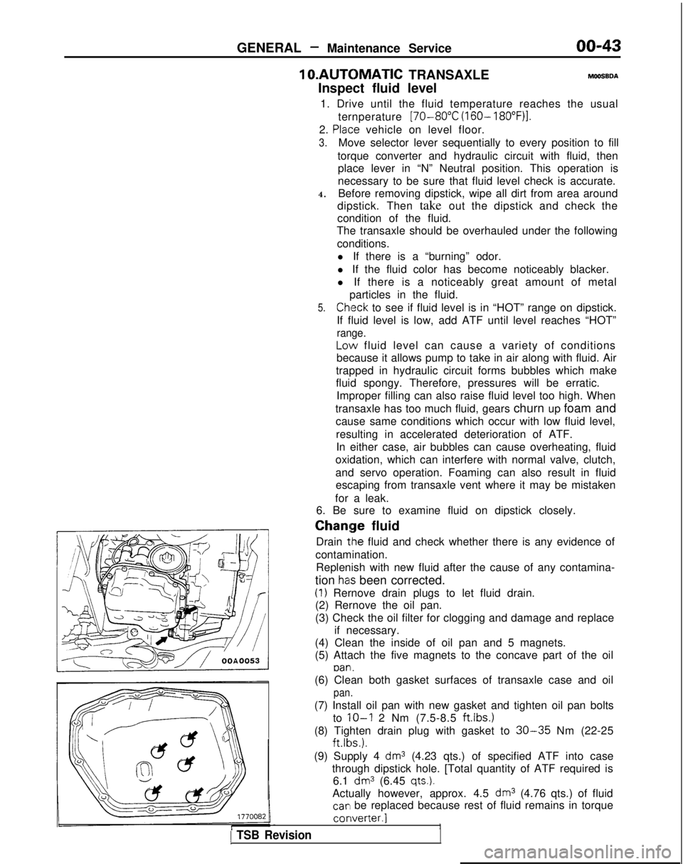
(1) Rernove drain plugs to let fluid drain.
(2) Rernove the oil pan.
(3) Check the oil filter for clogging and damage and replace
if necessary.
(4) Clean the inside of oil pan and 5 magnets.
(5) Attach the five magnets to the concave part of the oil
pan.
1 TSB Revision
(6) Clean both gasket surfaces of transaxle case and oil
pan.
(7) Install oil pan with new gasket and tighten oil pan bolts
to
IO-I 2 Nm (7.5-8.5 ftlbs.)
(8) Tighten drain plug with gasket to 30-35 Nm (22-25 ft.lbs.).
(9) Supply 4
dm3 (4.23 qts.) of specified ATF into case
through dipstick hole. [Total quantity of ATF required is 6.1
dm3 (6.45 qts.).
Actually however, approx. 4.5 dm3 (4.76 qts.) of fluid
car1 be replaced because rest of fluid remains in torque converter.]
1
Page 46 of 1273
GENERAL -Maintenance Service
(1O)Star-t engine and allow to idle for at least two minutes.
Then, with parking brake on, move selector
fever
momentarily to each position, ending in “N” Neutral
position.
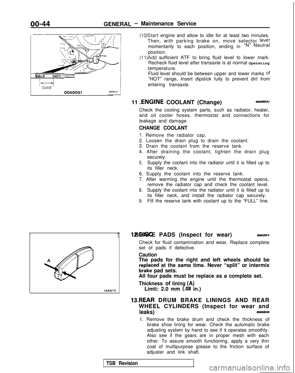
(11)Add sufficient ATF to bring fluid level to lower mark.
Recheck fluid level after transaxle is at normal Operating
temperature. Fluid level should be between upper and lower marks of
“HOT” range, Insert dipstick fully to prevent dirt from
entering transaxle.
OOA0051
11 .ENGINE
COOLANT (Change)MOOSEEAC
Check the cooling system parts, such as radiator, heater,
and oil cooler hoses, thermostat and connections for
leakage and damage.
CHANGE COOLANT
1. Remove the radiator cap.
2. Loosen the drain plug to drain the coolant.
3. Drain the coolant from the reserve tank.
4. After draining the coolant, tighten the drain plug securely.
5.Supply the coolant into the radiator until it is filled up to
its filler neck.
6. Supply the coolant into the reserve tank.
7. After warming the engine until the thermostat opens, remove the radiator cap and check the coolant level.
8.Supply the coolant into the radiator until it is filled up to
its filler neck, and install the radiator cap securely.
9.Fill the reserve tank with coolant up to the “FULL” line.
14K512
1 12.DISC BRAKE PADS (Inspect for wear) MWSBFA
Check for fluid contamination and wear. Replace complete
set of pads if defective.
Caution
The pads for the right and left wheels should be
reDlaced at the same time. Never “split” or intermix
brkke pad sets.
All four pads must be replace as a complete set.
Thickness of lining (A)
Limit: 2.0 mm (.08 in.)
13.REAR DRUM BRAKE LININGS AND REAR
WHEEL CYLINDERS (Inspect for wear and
leaks)MOOSBGB
1. Remove the brake drum and check the thickness of brake shoe lining for wear. Check the automatic brake
adjusting system by hand to see if it operates smoothly.
Also see if the gears are in proper mesh with each
other. To assure smooth functioning, apply a very thin
coat of multipurpose grease to the friction surface of
adjuster and link shaft.
TSB Revision1
Page 47 of 1273
14KO24
OOA0186
GENERAL - Maintenance Service00-45
2.Inspect the wheel cylinder boots for evidence of a brake
fluid leak. Visually check the boots for cuts, tears or heat cracks. (A slight amount of fluid on the boot may
not be a leak, but may be preservative fluid used at
assembly.)
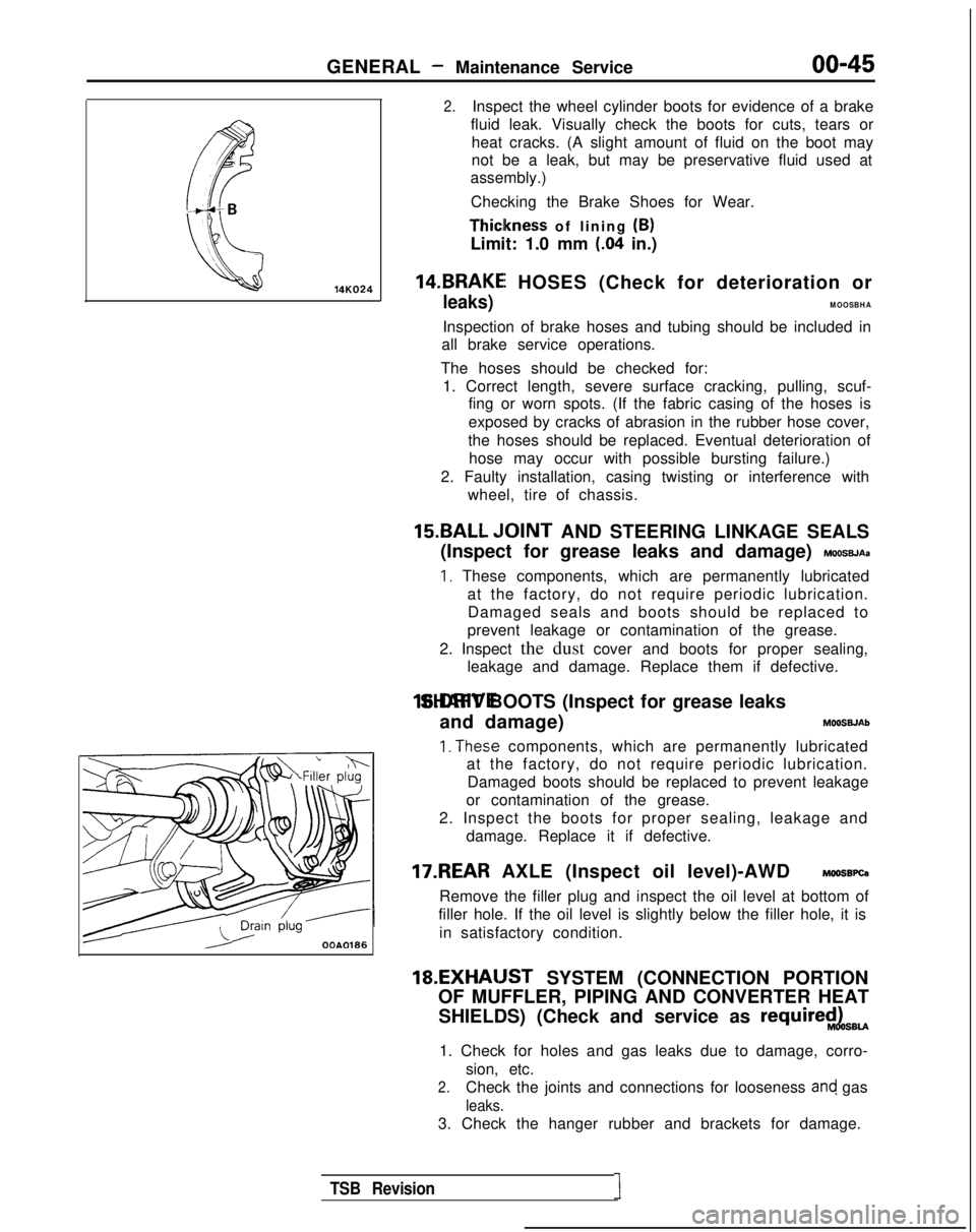
Checking the Brake Shoes for Wear. Thiclkness
of lining (B)
Limit: 1.0 mm
(.04 in.)
14.BRAKEI HOSES (Check for deterioration or
leaks)MOOSBHA
Inspection of brake hoses and tubing should be included in
all brake service operations.
The hoses should be checked for: 1. Correct length, severe surface cracking, pulling, scuf- fing or worn spots. (If the fabric casing of the hoses is
exposed by cracks of abrasion in the rubber hose cover,
the hoses should be replaced. Eventual deterioration of hose may occur with possible bursting failure.)
2. Faulty installation, casing twisting or interference with wheel, tire of chassis.
15.BALL ,IOINT AND STEERING LINKAGE SEALS
(Inspect for grease leaks and damage)
MOOSBJAa
I, These components, which are permanently lubricated at the factory, do not require periodic lubrication.Damaged seals and boots should be replaced to
prevent leakage or contamination of the grease.
2. Inspect the dust cover and boots for proper sealing, leakage and damage. Replace them if defective. 16.DRIVE SHAFT BOOTS (Inspect for grease leaks
and damage) MOOSWAb
1. The.se components, which are permanently lubricated
at the factory, do not require periodic lubrication.
Damaged boots should be replaced to prevent leakage
or contamination of the grease.
2. Inspect the boots for proper sealing, leakage and damage. Replace it if defective.
17.REAR AXLE (Inspect oil level)-AWD MOOSBPQ
Remove the filler plug and inspect the oil level at bottom of
filler hole. If the oil level is slightly below the filler hole, it is
in satisfactory condition. 18.EXHAIJST
SYSTEM (CONNECTION PORTION
OF MUFFLER, PIPING AND CONVERTER HEAT
SHIELDS) (Check and service as
require$LsBU
1. Check for holes and gas leaks due to damage, corro- sion, etc.
2.Check the joints and connections for looseness and gas
leaks.
3. Check the hanger rubber and brackets for damage.
TSB Revision1
Page 48 of 1273
00-46GENERAL - Table of Main Sealants and Adhesives
TABLEOF MAINSEALANTS
AND
ADHESIVES
MONA--
Application Recommended brand
1. Sealing for engine accessory parts 3M
ATD Part No.8660
or equivalent
(1) Sealing
for semi-circular packing of rocker cover and
cylinder head
(2) l
Sealrng for semi-circular packing and rocker cover, 3M
ATD Part No.8660
or equivalent
cylinder head
l Oil pressure switch
(3) l Engine coolant temperature switch l Engine coolant temperature sensor
l Thermal vacuum valvel Therm0
switch
l Engine coolant temperature gauge unit
l Joint 3M
Nut Locking Part
No.4171 or equivalent
(4) Oil pan MITSUBISHI GENUINE Part No.MD997110
or
equivalent
2. Sealing for weatherstrip
(1) l Sealing of tempered glass and weatherstrip 3M
ATD Part No. 8513 or equivalent
l Sealing
of body flange and weatherstrip 3M
ATD Part No.8509
or equivalent
(2) Sealing of laminated glass and weatherstrip 3M
ATD Part No.8509
or equivalent
3. Gluing with ribbon sealer l Door waterproof film
l Fender panel
l Splash shield
l Mud guard 3M
ATD Part No.8625
or equivalent
l Rear combination light TSB Revision
Page 51 of 1273
11-I
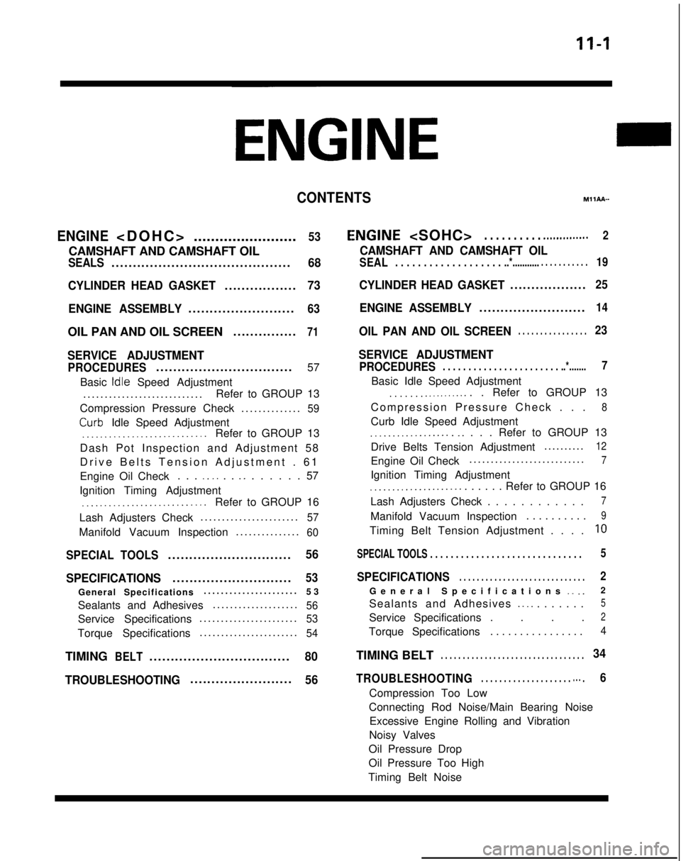
CONTENTSM11AA-
ENGINE
........................
53
CAMSHAFT AND CAMSHAFT OIL
SEALS..........................................68
CYLINDER HEAD GASKET
.................73
ENGINE ASSEMBLY
.........................63
OIL PAN AND OIL SCREEN ...............71
SERVICE ADJUSTMENT
PROCEDURES................................
57
Basic
Idle Speed Adjustment
...........................
.
Refer to GROUP 13
Compression Pressure Check ..............
59
Curb- Idle Speed Adjustment_.___..__._____....___._....Refer to GROUP 13
Dash Pot Inspection and Adjustment 58
Drive Belts Tension Adjustment . 6
1
Engine Oil Check . . .
_. _. . . _. . . . . . . 57
Ignition Timing Adjustment
__..._.__...................Refer to GROUP 16
Lash Adjusters Check ......................
.
57
Manifold Vacuum Inspection
..............
.
60
SPECIAL TOOLS.............................56
SPECIFICATIONS
............................53
General Specifications .....................
.
53
Sealants and Adhesives ....................
56
Service Specifications......................
.
53
Torque Specifications
......................
.
54
TIMINGBELT.................................80
TROUBLESHOOTING
........................56
E,NGINE
CAMSHAFT AND CAMSHAFT OIL
SEAL. . . . . . . . . . . . . . . . . . . ..*............ . . . . . . . . . .19
CYLINDER HEAD GASKET..................25
ENGINE ASSEMBLY.........................14
OIL PAN AND OIL SCREEN. . . . . . . . . . . . . . . .23
SERVICE ADJUSTMENT
PROCEDURES. . . . . . . . . . . . . . . . . . . . . . . ..*.......7
Basic Idle Speed Adjustment
. . . . . . . .._......... . Refer to GROUP 13
Compression Pressure Check . .
.
8
Curb Idle Speed Adjustment
.__................ _. . . . Refer to GROUP 13
Drive Belts Tension Adjustment .........
.
12
Engine Oil Check
..........................
.
7
Ignition Timing Adjustment
_...___............... . . . . . Refer to GROUP 16
Lash Adjusters Check . . . . . . . . . . . .
7
Manifold Vacuum Inspection . . . . . . . . . .9
Timing Belt Tension Adjustment . . . .10
SPECIAL TOOLS . . . . . . . . . . . . . . . . . . . . . . . . . . . . . \
.5
SPECIFICATIONS. . . . . . . . . . . . . . . . . . . . . . . . . . . . .2
General Specifications _. _.2
Sealants and Adhesives
._ _. . . . . . . .5
Service Specifications . . . .2
Torque Specifications . . . . . . . . . . . . . . . .4
TIMING BELT. . . . . . . . . . . . . . . . . . . . . . . . . . . . . . . . .34
TROUBLESHOOTING. . . . . . . . . . . . . . . . . . . . m.. .6
Compression Too Low
Connecting Rod Noise/Main Bearing Noise Excessive Engine Rolling and Vibration
Noisy Valves
Oil Pressure Drop
Oil Pressure Too High
Timing Belt Noise
Page 54 of 1273
II-4ENGINE
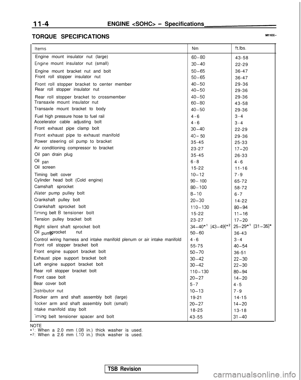
TORQUE SPECIFICATIONS Items
Nm ft.lbs.
Engine mount insulator nut (large)
60-8043-58
Engrne mount insulator nut (small)30-4022-29
Engine mount bracket nut and bolt
50-6536-47
Front roll stopper insulator nut
50-6536-47
Front roll stopper bracket to center member
40-5029-36
Rear roll stopper insulator nut
40-5029-36
Rear roll stopper bracket to crossmember
40-5029-36
Transaxle mount insulator nut
60-8043-58
Transaxle mount bracket to body
40-5029-36
Fuel high pressure hose to fuel rail 4-
6
3-4
Accelerator cable adjusting bolt 4-63-4
Front exhaust pipe clamp bolt
30-4022-29
Front exhaust pipe to exhaust manifold
40- 5029-36
Power steering oil pump to bracket 35-4525-33
Air conditioning compressor to bracket 23-27
17-20
Oil pan drain plug35-4526-33
Oilpan6-
8
4-6
Oil screen 15-2211-16
Timing belt cover
IO-127-
9
Cylinder head bolt (Cold engine)
90- 10065-72
Camshaft sprocket
80-10058-72
dater pump pulley bolt8-106-
7
Crankshaft pulley bolt
20-3014-22
Crankshaft sprocket bolt
110-13080-94
Timrng belt B tensioner bolt 15-2211-16
Tension pulley bracket bolt 23-2717-20
Right silent shaft sprocket bolt34-40”’ [43-49]*’ 25-29” [31-351”
Oil sprocket nut pump
50-6036-43
Control wiring harness and intake manifold plenum or air intake manifold\
4-
6
3-4
Front roll stopper bracket bolt 55-75
40-54
Front engine support bracket bolt50-7036-51
Exhaust pipe support bracket bolt
30-4222-30
Left engine support bracket bolt30-4222-30
Rear roll stopper bracket bolt110-13080-94
Front case bolt20-2714-20
Bear cover bolt 5-
7
4-5
Iistributor nutIO-137-
9
Rocker arm and shaft assembly bolt (large) 19-2114-15
?ocker arm and shaft assembly bolt (small)20-2714-20
ntake manifold stay bolt
18-2513-18
-iming belt tensioner spacer and bolt
43-5531-40
NOTE*I: When a 2.0 mm (.08 in.) thick washer is used.~2: When a 2.6 mm (.I0 in.) thick washer is used.
TSB Revision
Page 55 of 1273
ENGINE
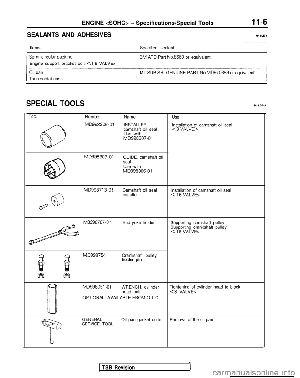
SEALANTS AND ADHESIVESMllCE-A
Items
Specified sealant
Engine support bracket bolt
3M
ATD Part
No.8660 or equivalent
MITSUBISHI GENUINE PART No.MD970389
or equivalent
SPECIAL TOOLSMl1 DA-A
ToolNumber
NameUse
6-J MD998306-01
INSTALLER,Installation of camshaft oil seal
camshaft oil seal(8 VALUE>
Q
Use with
MD998307-01
@
MD998307-01
GUIDE, camshaft oil
seal Use with
M D998306-01 MD998713-01
Camshaft oil seal
Installation of camshaft oil seal
6)
installer< 16 VALVE>
67%
MB990767-0 1End yoke holder Supporting camshaft pulley
Supporting crankshaft pulley
< 16 VALVE>
El iis
M D998754
Crankshaft pulley
b.holder pin
fa fii3
B
MD998051 -01WRENCH, cylinder Tightening of cylinder head to block
head bolt<8 VALVE>
OPTIONAL: AVAILABLE FROM O.T.C.
GENERAL
SERVICE TOOLOil pan gasket cutter Removal of the oil pan
TSB Revision
Page 56 of 1273
11-6
ToolENGINE
-Special Tools/Troubleshooting
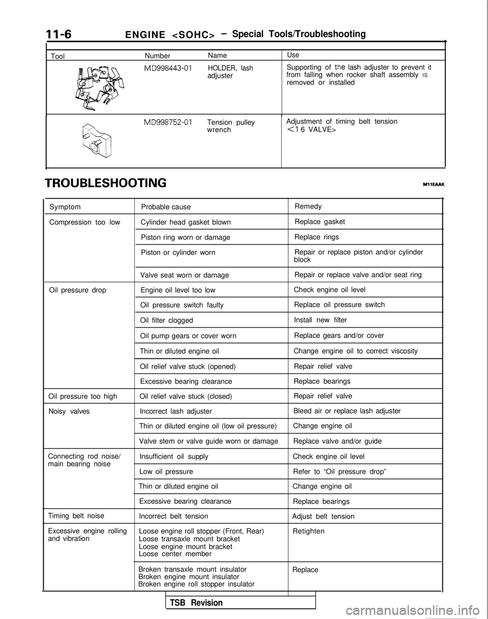
Number
NameUse
M
D998443-01 HOLDER, lashSupporting of the lash adjuster to prevent it
adjuster from falling when rocker shaft assembly
IS
removed or installed MD998752-01
Tension pulley Adjustment of timing belt tension
wrench
TROUBLESHOOTINGMHEAAK
Symptom
Compression too low Probable cause
Cylinder head gasket blown Piston ring worn or damage
Piston or cylinder worn Remedy
Replace gasket
Replace rings
Repair or replace piston and/or cylinder
block
Valve seat worn or damage Repair or replace valve and/or seat ring
Oil pressure drop Engine oil level too low Check engine oil level
Oil pressure switch faulty Replace oil pressure switch
Oil filter clogged Install new filter
Oil pump gears or cover worn Replace gears and/or cover
Thin or diluted engine oil Change engine oil to correct viscosity
Oil relief valve stuck (opened) Repair relief valve
Excessive bearing clearance Replace bearings
Oil pressure too high Oil relief valve stuck (closed) Repair relief valve
Noisy valves Incorrect lash adjuster Bleed air or replace lash adjuster
Thin or diluted engine oil (low oil pressure) Change engine oil
Valve stem or valve guide worn or damage Replace valve and/or guide
Connecting rod noise/ Insufficient oil supply Check engine oil level
main bearing noise
Low oil pressure Refer to “Oil pressure drop”
Thin or diluted engine oil Change engine oil
Excessive bearing clearance Replace bearings
Timing belt noise Incorrect belt tension Adjust belt tension
Excessive engine rolling Loose engine roll stopper (Front, Rear)
and vibration Retighten
Loose transaxle mount bracket
Loose engine mount bracket
Loose center member
Broken transaxle mount insulator
Broken engine mount insulator
Broken engine roll stopper insulator Replace
TSB Revision