1989 MITSUBISHI GALANT coolant level
[x] Cancel search: coolant levelPage 39 of 1273
GENERAL - Recommended LubricaMs and Lubricant Capacities Table 00-37
721004
4
Oil Identification Symbol
A standard
.symbol appears on the top of oil containers and has
three district areas for identifying various aspects of the oil.
The top
polqion will indicate the quality of the oil. The center
portion will show the SAE viscosity grade, such as SAE lOW-30.
“Energy Conserving” shown in the lower portion,
indicates that the oil has fuel-saving capabilities.
REAR AXLE
API classificationGL-5 or higher
Anticipated temperature range
Above -23°C
(- 10°F)
-23°C to --34°C (-10°F
to -30°F)
Viscosity range
SAE 90
SAE 85W-90SAE 8OW-90
SAE 8OW. SAE 8OW-90
Below
-34°C
(-30°F)SAE 75W
SELECTION OF COOLANT
COOLANT
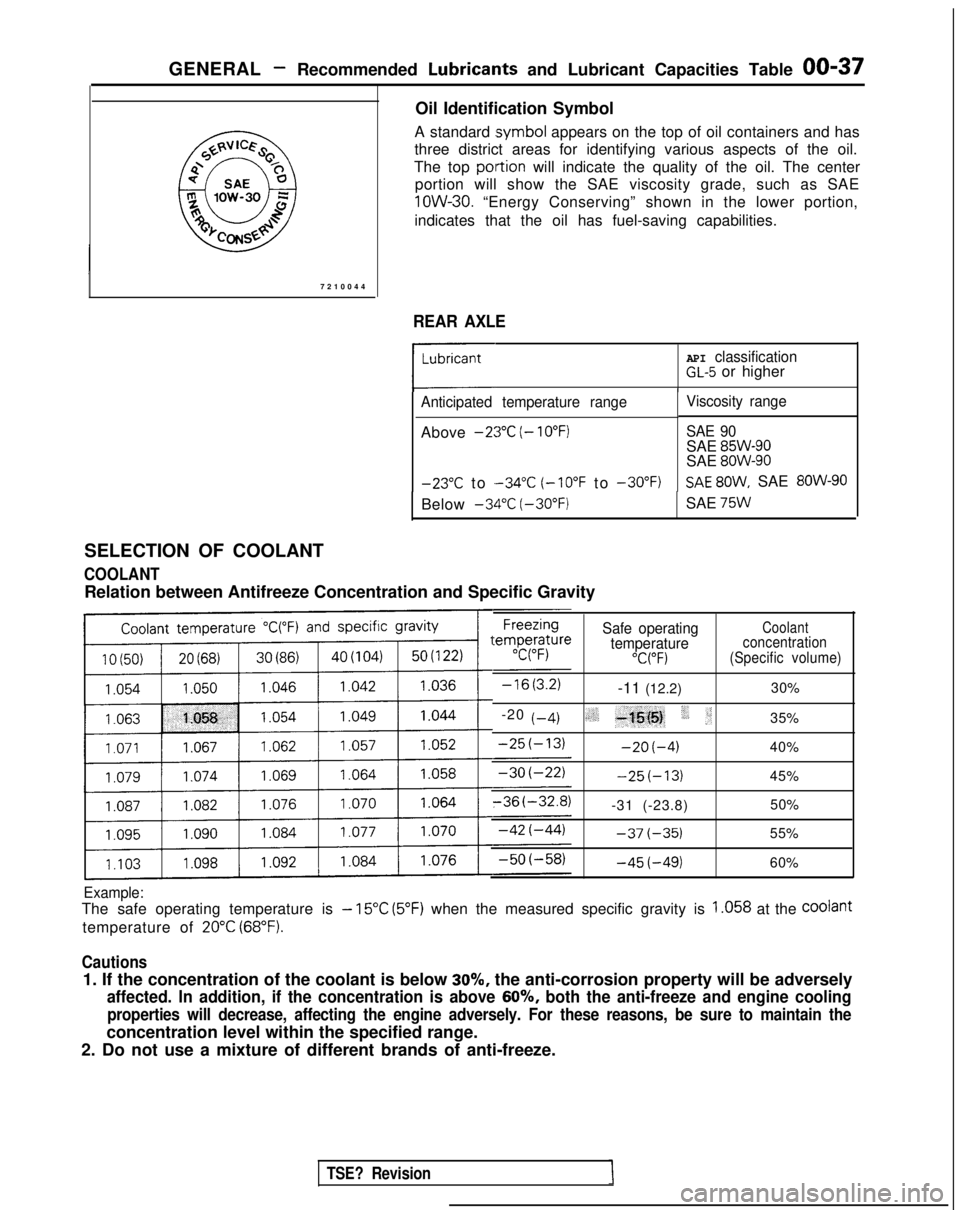
Relation between Antifreeze Concentration and Specific Gravity
Safe operatingCoolant
temperatureconcentration
“C(“F)(Specific volume)
-11 (12.2) 30%
-20
t-4)(,.‘_ -+j{@, ‘, :;35%
-2O(-4)40%
-25(-13)45%
-31 (-23.8) 50%
-37(-35)55%
-45(-49)60%
Example:
The safe operating temperature is - 15°C (5°F) when the measured specific gravity is 1.058 at the Coolant
temperature of 20°C (68°F).
Cautions
1. If the concentration of the coolant is below 30%, the anti-corrosion property will be adversely
affected. In addition, if the concentration is above 60%, both the anti-freeze and engine cooling
properties will decrease, affecting the engine adversely. For these reas\
ons, be sure to maintain the
concentration level within the specified range.
2. Do not use a mixture of different brands of anti-freeze.
TSE? Revision
Page 40 of 1273
00-38GENERAL- Scheduled Maintenance Table
SCHEDULED MAINTENANCE
TABLEMOOOA-
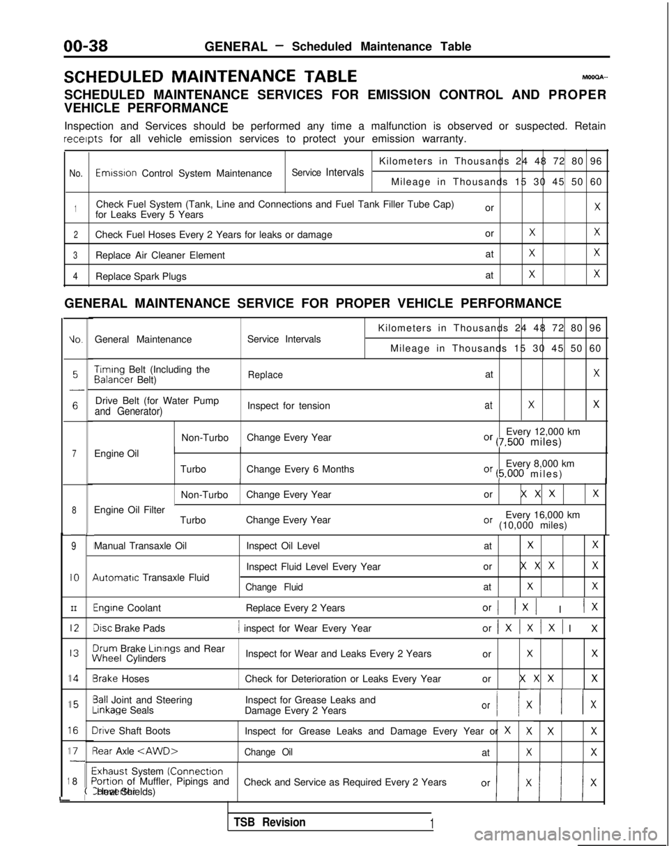
SCHEDULED MAINTENANCE SERVICES FOR EMISSION CONTROL AND PROPER
VEHICLE PERFORMANCE
Inspection and Services should be performed any time a malfunction is ob\
served or suspected. Retain receipts
for all vehicle emission services to protect your emission warranty.
Kilometers in Thousands 24 48 72 80 96
No.Emwsron Control System MaintenanceService IntervalsMileage in Thousands 15 30 45 50 60
1Check Fuel System (Tank, Line and Connections and Fuel Tank Filler Tube\
Cap) orXfor Leaks Every 5 Years
2Check Fuel Hoses Every 2 Years for leaks or damage orXX
3Replace Air Cleaner ElementatXX
4Replace Spark PlugsatXX
GENERAL MAINTENANCE SERVICE FOR PROPER VEHICLE PERFORMANCE
L
1
1
1
1
1
i
IO.General Maintenance
Service Intervals
7Engine Oil
8
9
IO
III2
I3
14
15
I6
I71
8
L
I
I
I
I
I\
I
II
I
I
;(
Kilometers in Thousands 24 48 72 80 96
Mileage in Thousands 15 30 45 50 60 Timing
Belt (Including the Balancer
Belt)
ReplaceatX
Drive Belt (for Water Pump
Inspect for tensionatXXand Generator)
Non-TurboChange Every Year Every 12,000 kmOr (7,500 miles)
Turbo Change Every 6 Months Every 8,000 km
Or (5.000 miles
)
II
Non-Turbo
Change Every Year or X X XX
Every 16,000 kmOr (10,000 miles)
Engine Oil Filter
TurboChange Every Year
Manual Transaxle Oil 4utomatrc
Transaxle Fluid Inspect Oil Level
at
XX
Inspect Fluid Level Every Yearor X X XX
Change FluidatXX
Engine Coolant
Replace Every 2 YearsOrI 1x1 I IX
Disc Brake Pads1 inspect for Wear Every Yearor/XlXlXl I
X
3rum
Brake Linings
and Rear iNheel
Cylinders Inspect for Wear and Leaks Every 2 Years
or
XX
3rake HosesCheck for Deterioration or Leaks Every Year or X X XX
3all Joint and SteeringInspect for Grease Leaks and-inkage
Seals
Damage Every 2 Years
Or I/ XII x
Irive Shaft Boots Inspect for Grease Leaks and Damage Every Year or XXXX
3ear Axle
Exhaust System (Connectron>ortion of Muffler, Pipings and
Check and Service as Required Every 2 YearsConverter Heat Shields)
TSB Revision1
Page 46 of 1273
GENERAL -Maintenance Service
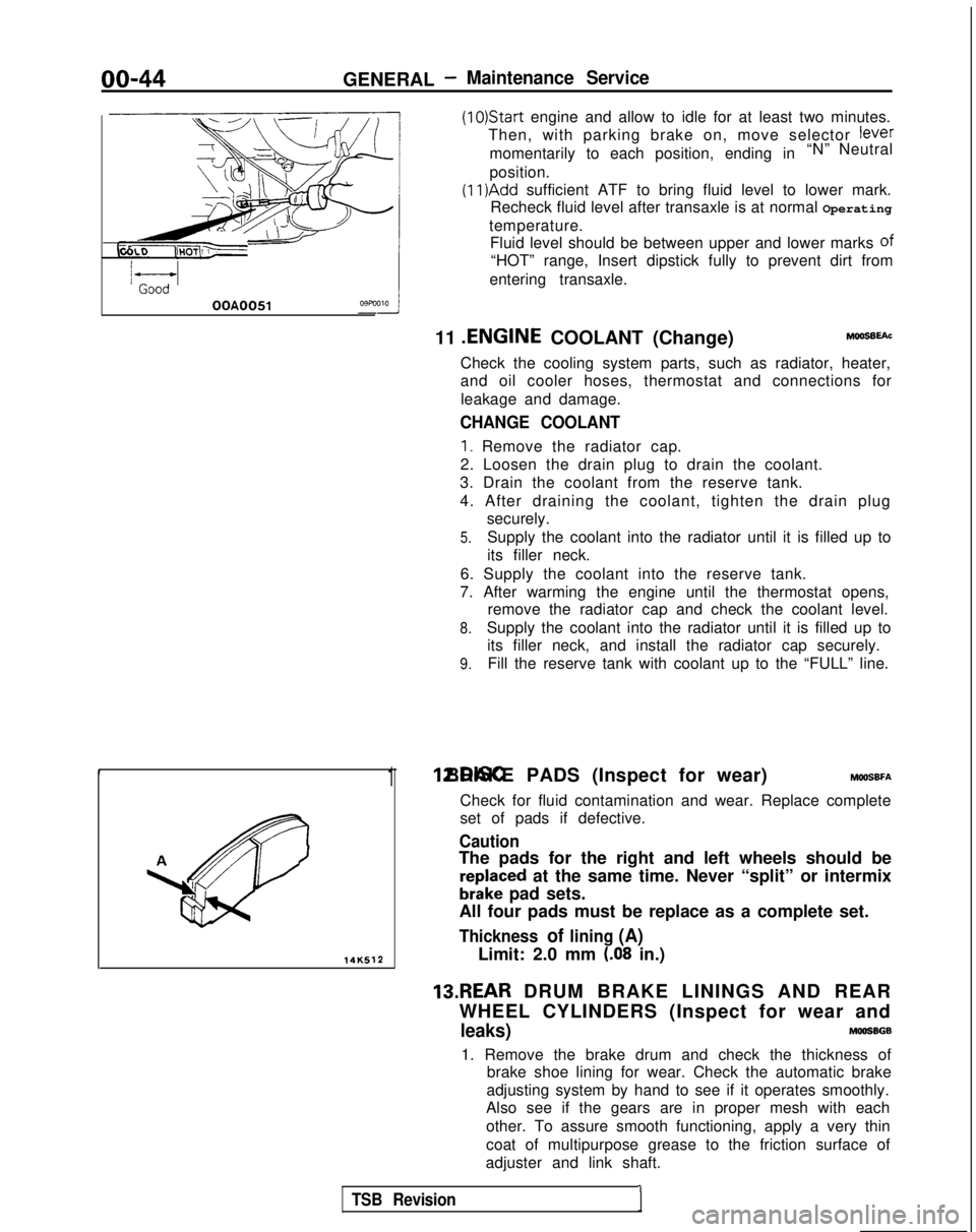
(1O)Star-t engine and allow to idle for at least two minutes.
Then, with parking brake on, move selector
fever
momentarily to each position, ending in “N” Neutral
position.
(11)Add sufficient ATF to bring fluid level to lower mark.
Recheck fluid level after transaxle is at normal Operating
temperature. Fluid level should be between upper and lower marks of
“HOT” range, Insert dipstick fully to prevent dirt from
entering transaxle.
OOA0051
11 .ENGINE
COOLANT (Change)MOOSEEAC
Check the cooling system parts, such as radiator, heater,
and oil cooler hoses, thermostat and connections for
leakage and damage.
CHANGE COOLANT
1. Remove the radiator cap.
2. Loosen the drain plug to drain the coolant.
3. Drain the coolant from the reserve tank.
4. After draining the coolant, tighten the drain plug securely.
5.Supply the coolant into the radiator until it is filled up to
its filler neck.
6. Supply the coolant into the reserve tank.
7. After warming the engine until the thermostat opens, remove the radiator cap and check the coolant level.
8.Supply the coolant into the radiator until it is filled up to
its filler neck, and install the radiator cap securely.
9.Fill the reserve tank with coolant up to the “FULL” line.
14K512
1 12.DISC BRAKE PADS (Inspect for wear) MWSBFA
Check for fluid contamination and wear. Replace complete
set of pads if defective.
Caution
The pads for the right and left wheels should be
reDlaced at the same time. Never “split” or intermix
brkke pad sets.
All four pads must be replace as a complete set.
Thickness of lining (A)
Limit: 2.0 mm (.08 in.)
13.REAR DRUM BRAKE LININGS AND REAR
WHEEL CYLINDERS (Inspect for wear and
leaks)MOOSBGB
1. Remove the brake drum and check the thickness of brake shoe lining for wear. Check the automatic brake
adjusting system by hand to see if it operates smoothly.
Also see if the gears are in proper mesh with each
other. To assure smooth functioning, apply a very thin
coat of multipurpose grease to the friction surface of
adjuster and link shaft.
TSB Revision1
Page 57 of 1273
ENGINE
OlR0340
1
SERVICE ADJUSTMENT PROCEDU$$o
ENGINE OIL CHECK
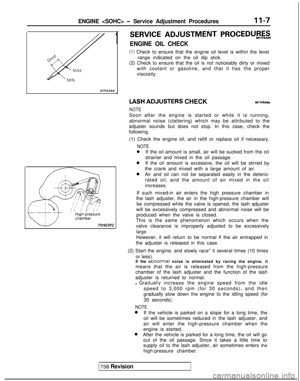
(1) Check to ensure that the engine oil level is within the level
range indicated on the oil dip stick.
(2) Check to ensure that the oil is not noticeably dirty or mixed
with coolant or gasoline, and that it has the proper
viscosity. IASH
ACIJUSTERS CHECKMllFEAGa
NOTE
Soon after the engine is started or while it is running,
abnormal noise (clattering) which may be attributed to the
adjuster sounds but does not stop. In this case, check the
following.
(1) Check the engine oil, and refill or replace oil if necessary.
NOTE
0If the oil amount is small, air will be sucked from the oil
strainer and mixed in the oil passage.
0If the oil amount is excessive, the oil will be stirred by
the crank and mixed with a large amount of air.
0Air and oil can not be separated easily in the deterio- rated oil, and the amount of air mixed in the oil
increases.
If such mixed-in air enters the high pressure chamber in
the lash adjuster, the air in the high-pressure chamber will be compressed while the valve is opened, the lash adjuster
will be excessively compressed and abnormal noise will be produced when the valve is closed.
This is the same phenomenon which occurs when the
valve clearance is improperly adjusted to be excessively
large.
However, it will return to be normal if the air entrapped in
the adjuster is released in this case.
(2) Start the engine, and slowly race* it several times (10 times or less).
If the
ablnormal noise is eliminated by racing the engine, it
means that the air is released from the high-pressure
chamber of the lash adjuster and the function of the lash
adjuster is returned to normal.
l
Graclually increase the engine speed from the idle
speed to 3,000 rpm (for 30 seconds), and then
gradually slow down the engine to the idling speed (for
30 seconds).
NOTE 0
If the vehicle is parked on a slope for a long time, the
oil will be sometimes reduced in the lash adjuster, and
air will enter the high-pressure chamber when the
engine is started. 0
After the vehicle is parked for a long time, the oil will go
out of the oil passage. Since it takes a little time to
supply oil to the lash adjuster, air sometimes enters the
high-pressure chamber.
1 TSB Revision
Page 107 of 1273
ENGINE
OlR0340
7EN0393
1SERVICE ADJUSTMENT PROCEDUBFzo
ENGINE OIL CHECK
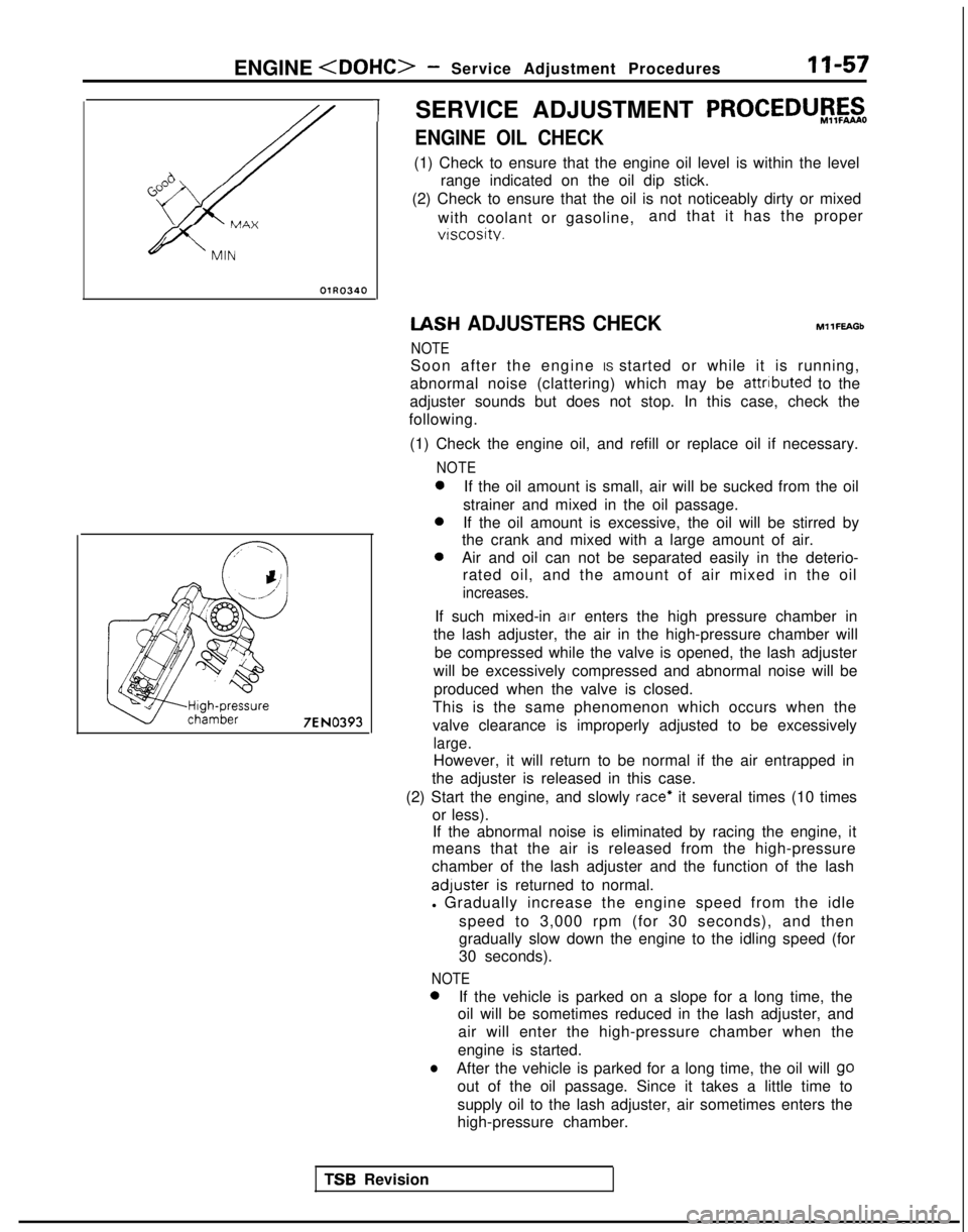
(1) Check to ensure that the engine oil level is within the level
range indicated on the oil dip stick.
(2) Check to ensure that the oil is not noticeably dirty or mixed
with coolant or gasoline, and that it has the proper
vtscosity. IASH
ADJUSTERS CHECK
NOTE MllFEAGb
Soon after the engine IS started or while it is running,
abnormal noise (clattering) which may be attributed
to the
adjuster sounds but does not stop. In this case, check the
following.
(1) Check the engine oil, and refill or replace oil if necessary.
NOTE 0
If the oil amount is small, air will be sucked from the oil
strainer and mixed in the oil passage. 0
If the oil amount is excessive, the oil will be stirred by
the crank and mixed with a large amount of air. 0
Air and oil can not be separated easily in the deterio-
rated oil, and the amount of air mixed in the oil
increases.
If such mixed-in air enters the high pressure chamber in
the lash adjuster, the air in the high-pressure chamber will
be compressed while the valve is opened, the lash adjuster
will be excessively compressed and abnormal noise will be produced when the valve is closed.
This is the same phenomenon which occurs when the
valve clearance is improperly adjusted to be excessively
large.
However, it will return to be normal if the air entrapped in
the adjuster is released in this case.
(2) Start the engine, and slowly
race* it several times (10 times
or less). If the abnormal noise is eliminated by racing the engine, it
means that the air is released from the high-pressure
chamber of the lash adjuster and the function of the lash adluster
is returned to normal.
l Gradually increase the engine speed from the idle
speed to 3,000 rpm (for 30 seconds), and then
gradually slow down the engine to the idling speed (for
30 seconds).
NOTE 0
If the vehicle is parked on a slope for a long time, the
oil will be sometimes reduced in the lash adjuster, and
air will enter the high-pressure chamber when the
engine is started.
lAfter the vehicle is parked for a long time, the oil will go
out of the oil passage. Since it takes a little time to
supply oil to the lash adjuster, air sometimes enters the
high-pressure chamber.
TSR Revision
Page 555 of 1273

COOLING- Specifications14-3
Items Specifications
Engine coolant temperature gauge unit ResistanceAt
70°C (158°F)n 104f13.5
Engine coolant temperature sensor (Engine control) ResistanceAt
20°C (68°F)kQ 2.45 f 0.24
At 80°C (176°F)Q 296+32
Air conditioning engine coolant temperature switch
ON
+ OFF operating temperature“C (“F) 112-118 (234-244
)
Engine coolant temperature switch
(Air conditioning or A/T control)
OFF
+ ON operating temperature“C (“F) 100-104 (212-219
)
Limit
Opening pressure of radiator cap high pressure valvekPa (psi) 65 (9.2)
TORQUE SPECIFICATIONS
MWCG-
ItemsNm ft.lbs.
Radiator upper insulator 9-14
7-10
Reserve tank, bracket installation bolt9-1
4
7-10
Thermosensor to radiator35
25
Automatic transaxle oil coole: hose cramp 4-
6
3-4
Automatic transaxle oil cooler hose mounting bolt 3-5
2-4
Water outlet fitting bolts
17-2012-14
Water inlet fitting bolts
IO-157-10
Engine mount insulator nut (large)60-8043-58
Engine mount insulator nut (small)
\ 30-4022-29
Engine mount bracket to engine
50-6536-47
Bracket between engine mount bracket and engine 17-26
12-19
Water pump installation bolt Bolt head mark “4T”
12-15
9-l 1
Bolt head mark “7T”20-2714-20
dater pump pulley bolt8-106-
7
Jamper pulley, crankshaft pulley20-3014-22
Timing belt front upper cover installation bolt
IO-127-
9
Timing belt front lower cover installation bolt
IO-127-
9
Crankshaft
sprocket installation bolt
110-13080-94
Timing belt B tensioner 15-2211-16
Tension pulley bracket for air conditioning
23-2717-20
Automatic tensioner installation bolt20-2714-20
Tensioner pulley installation bolt43-5531-40
Oil level gauge 12-159-l 1
Front exhaust pipe to exhaust manifold
Front exhaust pipe bracket
30-4022-29
Exhaust manifold cover (A), (B)
9-11
Heat protector
TSB Revision
Page 560 of 1273
14-8
COOLING -Service Adjustment Procedures T210863
SERVICE ADJUSTMENT PROCEDUl$t&
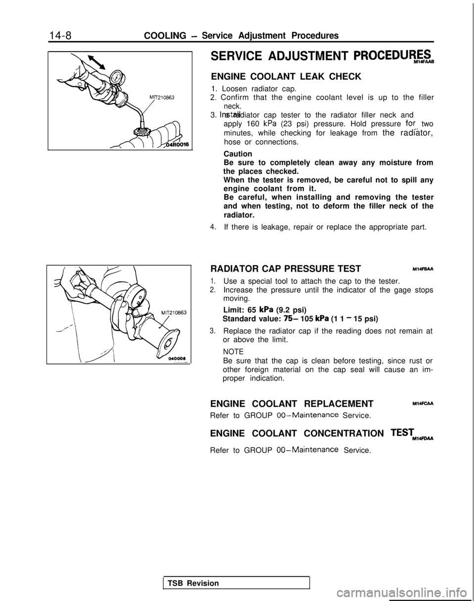
ENGINE COOLANT LEAK CHECK
1. Loosen radiator cap.
2. Confirm that the engine coolant level is up to the filler
neck.
3. Install a radiator cap tester to the radiator filler neck and
apply 160
kPa (23 psi) pressure. Hold pressure for. two
minutes, while checking for leakage from the radiator, hose or connections.
Caution
Be sure to completely clean away any moisture from
the places checked. When the tester is removed, be careful not to spill anyengine coolant from it.
Be careful, when installing and removing the tester
and when testing, not to deform the filler neck of the
radiator.
4.If there is leakage, repair or replace the appropriate part.
RADIATOR CAP PRESSURE TEST
MlOFBAA
1.Use a special tool to attach the cap to the tester.
2.Increase the pressure until the indicator of the gage stops
moving.
Limit: 65
kPa (9.2 psi)
Standard value:
75- 105 kPa (1 1 - 15 psi)
3.Replace the radiator cap if the reading does not remain at
or above the limit.
NOTE
Be sure that the cap is clean before testing, since rust or
other foreign material on the cap seal will cause an im-
proper indication.
ENGINE COOLANT REPLACEMENT
MMFCAA
Refer to GROUP 00-Maintenance Service.
ENGINE COOLANT CONCENTRATION TEST,,wti
Refer to GROUP
00-Maintenance Service.
TSB Revision
Page 765 of 1273
AUTOMATIC TRANSAXLE - Troubleshooting23-59
ring
brake
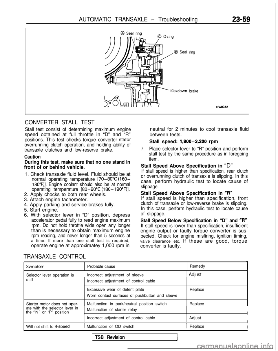
CONVERTER STALL TEST
Stall test consist of determining maximum engine
speed obtained at full throttle in “D” and “R”
positions. This test checks torque converter stator
overrunning clutch operation, and holding ability of
transaxle clutches and low-reserve brake.
Caution
During this test, make sure that no one stand in
front of or behind vehicle.
1. Check transaxle fluid level. Fluid should be at
normal operating temperature [70-80°C (160-
18O”F)j. Engine coolant should also be at normal
operating temperature
[80-90°C (180-19O”F)l.
2. Apply chocks to both rear wheels.
3. Attach engine tachometer.
4. Apply parking and service brakes fully.
5. Start engine.
6. With selector lever in “D” position, depress
accelerator pedal fully to read engine maximum
rpm. Do not hold throttle wide open any longer
than is necessary to obtain maximum engine
rpm reading, and never longer than 5 seconds at
a time. If more than one stall test is required,
operate engine at approximatey 1,000 rpm in
TRANSAXLE CONTROL
neutral for 2 minutes to cool transaxle fluid
between tests.
Stall speed: 1,800-3,200
rpm
7.Place selector lever to “R” position and perform
stall test by the same procedure as in foregoing
item.
Stall Speed Above Specification in “D”
If stall speed is higher than specification, rear clutch
or overrunning clutch of transaxle is slipping. In this
case, perform hydraulic test to locate cause of
slippage.
Stall Speed Above Specification in “I?”
If stall speed is higher than specification, front
clutch of transaxle or low-reverse brake is slipping. In this case, perform hydraulic test to locate cause
of slippage.
Stall Speed Below Specification in “D” and “R”
If stall speed is lower than specification, insufficient
engine output or faulty torque converter is sus-
pected. Check for engine misfiring, ignition timing,
valve clearance etc. If these are good, torque
converter is faulty. Svmotom
Probable cause
Remedy
Selector lever operation is Incorrect adjustment of sleeve
1 Adjust
stiff
Starter motor does not oper-
Incorrect adjustment of control cable
Excessive wear of detent plate
Worn contact surfaces of pushbutton and sleeve
Malfunction in park/neutral position switch Replace
Replace
ate with the selector lever in
the
“N” or “P” position Malfunction of starter relayI
Incorrect adjustment of control cable
AdjustI
W
ill not shift to 4-speed
( Malfunction of OD switch) ReplaceI
TSB Revision