1989 MITSUBISHI GALANT wheel bolt torque
[x] Cancel search: wheel bolt torquePage 832 of 1273
26-2
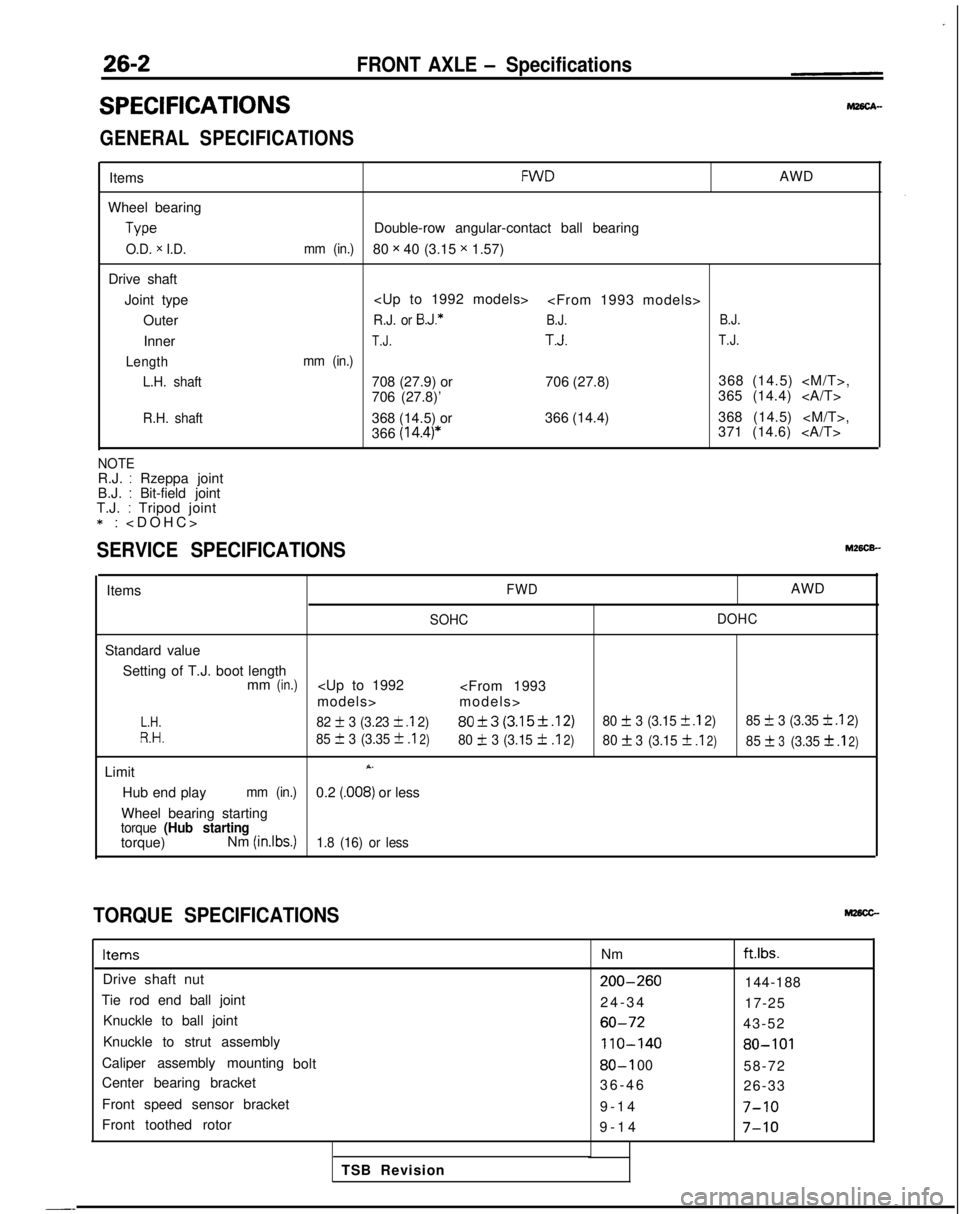
SPECIFICATIONS
FRONT AXLE - Specifications
GENERAL SPECIFICATIONS
Items
Wheel bearing Type
O.D. x I.D.
Drive shaft
Joint type Outer
Inner
Length L.H. shaft
R.H. shaft
FWDAWD
Double-row angular-contact ball bearing
mm (in.)80 x 40 (3.15 x 1.57)
R.J. or B.J.*B.J. B.J.
T.J.T.J.T.J.
mm (in.)
708 (27.9) or
706 (27.8)368 (14.5)
706 (27.8)’ 365 (14.4)
368 (14.5) or 366 (14.4)368 (14.5)
366
(14.4)*371 (14.6)
NOTER.J. : Rzeppa joint
B.J. : Bit-field joint
T.J. : Tripod joint *:
>
SERVICE SPECIFICATIONS
ItemsFWDAWD
SOHC
DOHC
Standard value
Setting of T.J. boot length mm
(in.)
L.H.82 + 3 (3.23 k .I 2)80f3 (3.15f.12)80 + 3 (3.15 f .I 2)
85 f 3 (3.35 k .I 2)
R.H.85 III 3 (3.35 +
.I2)80 IL 3 (3.15 f.I2)80f3
(3.15f .I2)85f3(3.3531
.I2)
LimitX.
Hub end playmm (in.)0.2 (.008) or less
Wheel bearing starting
torque (Hub startingtorque) Nm (inlbs.)1.8 (16) or less
TORQUE SPECIFICATIONS
ItemsNmftlbs.
Drive shaft nut200-260144-188
Tie rod end ball joint 24-3
4
17-25
Knuckle to ball joint
60-7243-52
Knuckle to strut assembly
110-14080-101
Caliper assembly mounting bolt80-I 0058-72
Center bearing bracket 36-4
6
26-33
Front speed sensor bracket 9-14
7-10
Front toothed rotor9-1
4
7-10
TSB Revision
-_
Page 864 of 1273
27-4REAR AXLE
11 PO033
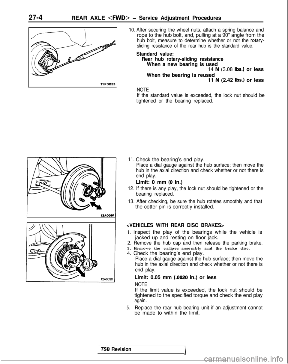
10. After securing the wheel nuts, attach a spring balance and
rope to the hub bolt, and, pulling at a 90” angle from the
hub bolt, measure to determine whether or not the rotary-
sliding resistance of the rear hub is the standard value.
Standard value: Rear hub rotary-sliding resistance
When a new bearing is used 14
N (3.08 Ibs.) or less
When the bearing is reused 11
N (2.42 Ibs.) or less
NOTE
If the standard value is exceeded, the lock nut should be
tightened or the bearing replaced.
11. Check the bearing’s end play.
Place a dial gauge against the hub surface; then move the
hub in the axial direction and check whether or not there is
end play.
Limit: 0 mm (0 in.)
12. If there is any play, the lock nut should be tightened or the
bearing replaced.
13. After checking, be sure the hub rotates smoothly and that
the cotter pin is correctly installed.
1. Inspect the play of the bearings while the vehicle is jacked up and resting on floor jack.
2. Remove the hub cap and then release the parking brake.
3. Remove the caliper assembly and the brake disc.
4. Check the bearing’s end play.
Place a dial gauge against the hub surface; then move the
hub in the axial direction and check whether or not there is
end play.
Limit: 0.05 mm (.0020 in.) or less
NOTE
If the limit value is exceeded, the lock nut should be
tightened to the specified torque and check the end play
again.
5.Replace the rear hub bearing unit if an adjustment cannot
be made to within the limit.
TSB RevisionI
Page 871 of 1273
REAR AXLE
Items
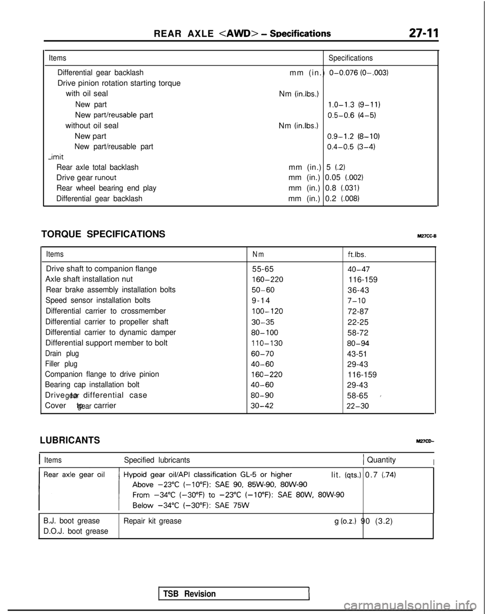
Differential gear backlash
Drive pinion rotation starting torque
with oil seal
New part
New part/reusable part
without oil seal New part
New part/reusable part -imit
Rear axle total backlash
Drive gear runout
Rear wheel bearing end play
Differential gear backlash
Specifications
mm (in.) O-0.076 (O-.003)
Nm (in.lbs.) 1.0-1.3
(9-11)
0.5-0.6
(4-5)
Nm
(in.lbs.1 0.9-1.2
(8-10)
0.4-0.5
(3-4)
mm (in.) 5
(2)
mm (in.) 0.05 (.002)
mm (in.) 0.8 (.031)
mm (in.) 0.2 (008)
TORQUE SPECIFICATIONSM27cc-B
ItemsNmft.lbs.
Drive shaft to companion flange 55-6540-47
Axle shaft installation nut 160-220
116-159
Rear brake assembly installation bolts50-6036-43
Speed sensor installation bolts9-1
4
7-10
Differential carrier to crossmember
100-120
72-87
Differential carrier to propeller shaft30-3522-25
Differential carrier to dynamic damper80- 10058-72
Differential support member to bolt 110-130
80-94
Drain plug60-7043-51
Filler plug40-6029-43
Companion flange to drive pinion
160-220
116-159
Bearing cap installation bolt40-6029-43
Drive to differential case
gear80-9058-651
Cover to carriergear30-4222-30
TSB Revision
LUBRICANTS
IItemsSpecified lubricants1 QuantityI
lit. (qts.) 0.7 (74)
B.J. boot grease Repair kit grease
g (oz.) 90 (3.2)
D.O.J. boot grease
Page 876 of 1273
REAR AXLE
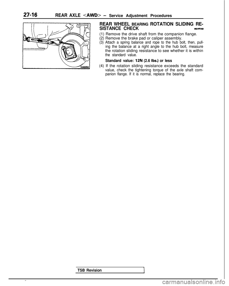
REAR WHEEL BEARING ROTATION SLIDING RE-
SISTANCE CHECKnnnFFA6
(1) Remove the drive shaft from the companion flange.
(2) Remove the brake pad or caliper assembly.
(3) Attach a spring balance and rope to the hub bolt, then, pull-
ing the balance at a right angle to the hub bolt, measure
the rotation sliding resistance to see whether it is within
the standard value.
Standard value: 12N (2.6 Ibs.) or less
(4) If the rotation sliding resistance exceeds the standard
value, check the tightening torque of the axle shaft com-
panion flange. If it is normal, replace the bearing.
TSB Revision
Page 1098 of 1273
REAR SUSPENSION
Lateral rodmounting bolt
1 Turn 180” or more ant1
TSB Revision
SERVICE POINTS OF INSTALLATIONMtOPDAH
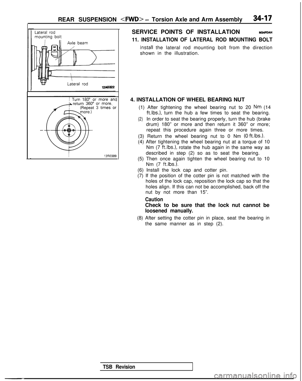
11. INSTALLATION OF LATERAL ROD MOUNTING BOLT
Install the lateral rod mounting bolt from the direction
shown in the illustration.
4. INSTALLATION OF WHEEL BEARING NUT (1) After tightening the wheel bearing nut to 20
Nm (14 ft.lbs.),
turn the hub a few times to seat the bearing.
(2)In order to seat the bearing properly, turn the hub (brake
drum) 180” or more and then return it 360” or more;
repeat this procedure again three or more times.
(3) Return the wheel bearing nut to 0 Nm
(0 ftlbs.).
(4) After tightening the wheel bearing nut at a torque of 10 Nm (7
ftlbs.), rotate the hub again in the same way as
described in step (2) so as to seat the bearing.
(5) Then once again tighten the wheel bearing nut to 10 Nm (7 ft.lbs.).
(6) Install the lock cap and cotter pin.
(7) If the position of the cotter pin is not matched with the holes of the lock cap, reposition the lock cap so that the
holes align. If this can not be accomplished, back off the
nut by not more than 15”.
Caution
Check to be sure that the lock nut cannot be
loosened manually.
(8) After setting the cotter pin in place, seat the bearing in
the same manner as in step (2).
Page 1130 of 1273
![MITSUBISHI GALANT 1989 Service Repair Manual SERVICE BRAKES - Specifications35-9
SERVICE SPECIFICATIONS [1993 models]
ItemsSOHCDOHC
Standard value
Brake pedal height mm (in.) 176-181 (6.9-7.1)
176-181 (6.9-7.1)
Brake pedal free play mm (in.)3-8 MITSUBISHI GALANT 1989 Service Repair Manual SERVICE BRAKES - Specifications35-9
SERVICE SPECIFICATIONS [1993 models]
ItemsSOHCDOHC
Standard value
Brake pedal height mm (in.) 176-181 (6.9-7.1)
176-181 (6.9-7.1)
Brake pedal free play mm (in.)3-8](/manual-img/19/57312/w960_57312-1129.png)
SERVICE BRAKES - Specifications35-9
SERVICE SPECIFICATIONS [1993 models]
ItemsSOHCDOHC
Standard value
Brake pedal height mm (in.) 176-181 (6.9-7.1)
176-181 (6.9-7.1)
Brake pedal free play mm (in.)3-8 (.I
-.3)3-8 (.I -.3)
Brake pedal to floorboard clearance
mm (in.)80 (3.1) or more 80 (3.1) or more
Proportioning valve pressure MPa
(psi)
Split point 3.95-4.45
(561-633)3.45-3.95 (491-561)
Output pressure5.55-6.05 (789-861)4.65-5.15 (661-732)
[input pressure][8.2 (1 ,I 63)][7.7 (1,095)]
Booster push rod to master cylinder piston clearancemm (in.)
9 inch brake booster0.8-l .O (.031-,039)0.8- 1 .O (.031-.039)
7
+ 8 inch brake booster0.5-0.7 (.020-.028)
Disc brake drag force (tangential force of wheel mounting bolts)
N (Ibs.)70 (15.4) or less 70 (15.4) or less
[Disc brake dragging torque] Nm (ftlbs.)[4 (3) or less] [4 (3) or less]
Speed sensor’s internal resistance
k& -0.8- 1.2*
Clearance between the speed pole piece and the toothed rotor mm (in.) -0.3-0.9 (.012-.035)*
-imit
Left/right proportioning valve output pressure difference
MPa
(psi) 0.4 (57)0.4 (57)
Front disc runout
mm (in.) 0.07 (.0028)0.07 (0028)
Pad thickness mm (in.) 2.0
(.08)2.0 (.08)
Front disc thickness
mm (in.) 22.4 (.882)22.4 (882)
Rear disc thickness
mm(in.) -8.4 (.331)
Rear disc runout
mm (in.) -0.08 (.003 1)
Rear drum lining thicknessmm (in.)1 .O (04)
Rear drum inside diameter
mm (in.) 205 (8.1)
NOTE* : Vehicles with A.B.S.
TSB Revision
Page 1179 of 1273
35-58SERVICE BRAKES - Service Adjustment Procedures
14*ooat
Delay
valve Bleeder screw
(for the left rear brakes)i
Bleeder screw
I.LOO.1lheck valve bolt20-25 Nm (14-18 ft.lbs.)
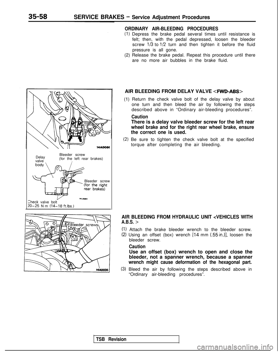
ORDINARY AIR-BLEEDING PROCEDURES
(1) Depress the brake pedal several times until resistance is
felt; then, with the pedal depressed, loosen the bleederscrew
113 to l/2 turn and then tighten it before the fluid
pressure is all gone.
(2) Release the brake pedal. Repeat this procedure until there
are no more air bubbles in the brake fluid.
AIR BLEEDING FROM DELAY VALVE
4WD-ABS>
(1) Return the check valve bolt of the delay valve by about one turn and then bleed the air by following the steps
described above in “Ordinary air-bleeding procedures”.
Caution
There is a delay valve bleeder screw for the left rear
wheel brake and for the right rear wheel brake, ensure
the correct one is used.
(2) Be sure to tighten the check valve bolt at the specified
torque after completing the air bleeding.
AIR BLEEDING FROM HYDRAULIC UNIT
(1) Attach the brake bleeder wrench to the bleeder screw.
(2) Using an offset (box) wrench 114 mm (55 in.)], loosen the
bleeder screw.
Caution
Use an offset (box) wrench to open and close the
bleeder, not a spanner wrench, because a spanner
wrench might cause deformation of the hexagonal part.
(3) Bleed the air by following the steps described above in “Ordinary air-bleeding procedures”.
TSB Revision
Page 1190 of 1273
SERVICE BRAKES - Service Adjustment Procedures35-69
(5) The probable cause if the output voltage is 50 mV or lower, or if the one-side deflection width of the
oscilloscope’s waveform is 70
mV or lower
Probable causes Remedy
Excessive clearance between the speed sensor pole
piece and rotor Adjust to the standard value.
Foreign material attached to the speed sensor pole
pieceRemove the foreign material.
Damaged speed sensor pole pieceReplace the speed sensor.
Damaged rotor teeth~~~ rReplace the rotor.
Loose speed sensor or rotor installation bolt I
Tighten to the specified torque.
1
NOTE
The speed sensor internal resistance and harness side are normal.
Caution
It is conceivable, because the movement of a speed-sensor cable “foll\
ows” the movement of the front
or rear suspension, that the damaged wiring condition may be apparent on\
ly during travel on poor
road surfaces, and may be normal on better road surfaces. Therefore, whe\
n measuring the output
voltage of a speed sensor, recheck the condition of the cable connection\
s by removing the clamp and pulling the cable and bending it near the clamp position in order to che\
ck for the existence of damaged
wiring.
1/21314j51617)61Q~10~11~12)13~14~15)16~17~1~~19~20~21~22~23~24~25~26(27~26~2Q~30(31~32~33~34~35~
Check connector
74=f=n
ECU
*
Body harnessMB991 356fl 14N018C
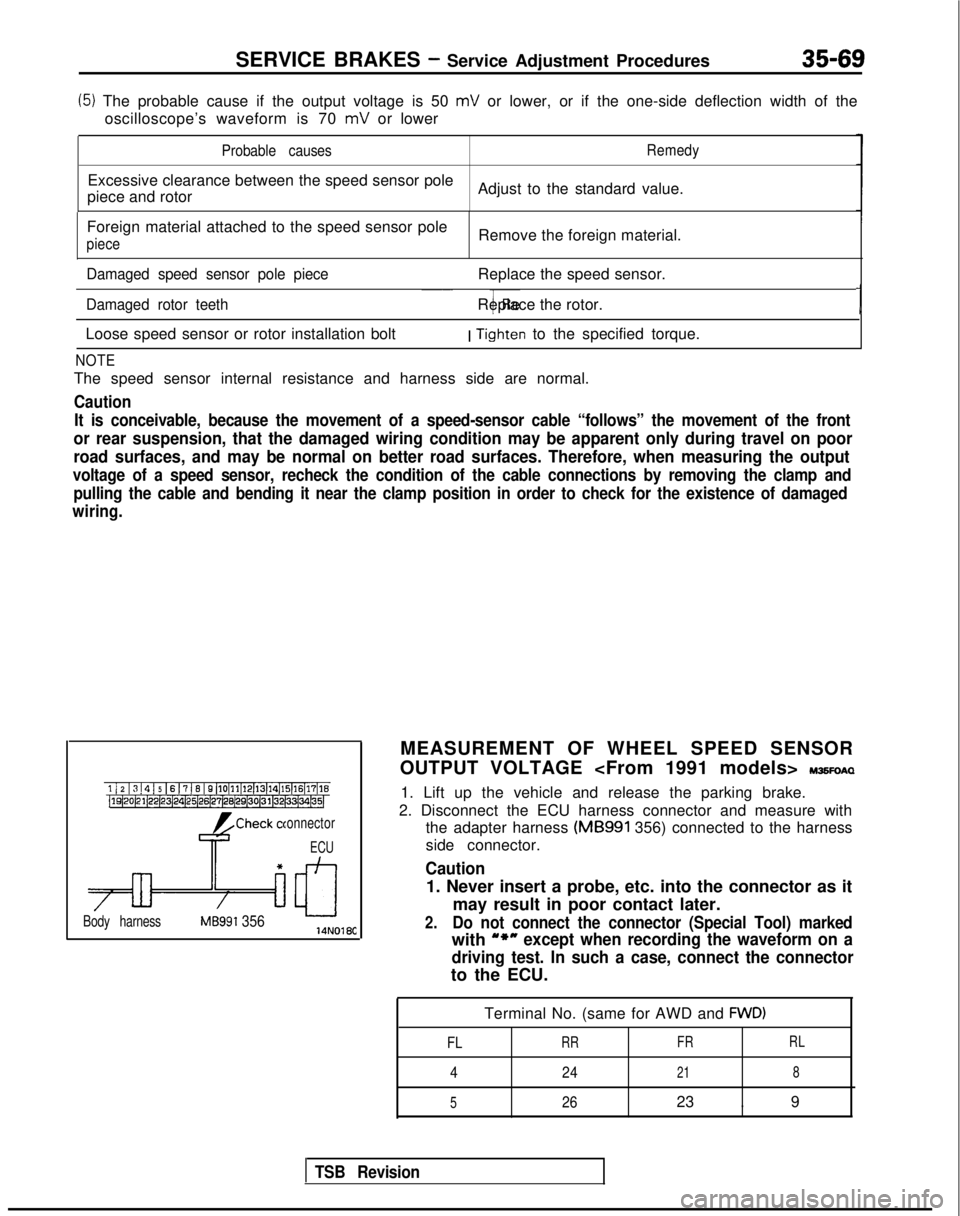
MEASUREMENT OF WHEEL SPEED SENSOR
OUTPUT VOLTAGE
IWSFOAQ
1. Lift up the vehicle and release the parking brake.
2. Disconnect the ECU harness connector and measure with the adapter harness (MB991
356) connected to the harness
side connector.
Caution
1. Never insert a probe, etc. into the connector as it
may result in poor contact later.
2.Do not connect the connector (Special Tool) marked
with u*nexcept when recording the waveform on a
driving test. In such a case, connect the connector
to the ECU.
Terminal No. (same for AWD and
FWD)
FL
RR FRRL
4
24218
5
2623 . 9
TSB Revision