1989 MITSUBISHI GALANT sport mode
[x] Cancel search: sport modePage 957 of 1273
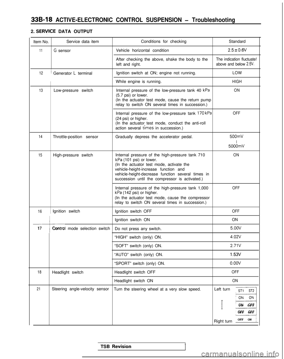
33B-18 ACTIVE-ELECTRONIC CONTROL SUSPENSION - Troubleshooting
2. SERlflCE DATA OUTPUT
Item No. Service data item
Conditions for checking
Standard
11G sensorVehicle horizontal condition2.520.6V
After checking the above, shake the body to theThe indication fluctuate!
left and right.above and below 2.5V.
12/ Generator L terminalIgnition switch at ON; engine not running.LOW
While engine is running.HIGH
13Low-pressure switch
Internal pressure of the low-pressure tank 40 kPaON
(5.7 psi) or lower.
(In the actuator test mode, cause the return pump
relay to switch ON several times in succession.)
Internal pressure of the low-pressure tank
170 kPa
(24 psi) or higher.
(In the actuator test mode, conduct the anti-roll
action several
times in succession.)
OFF
14Throttle-position sensor Gradually depress the accelerator pedal. 500mV
I
5000mV
15High-pressure switch
Internal pressure of the high-pressure tank 710ON
kPa (101 psi) or lower.
(In the actuator test mode, activate the
vehicle-height-increase function and
vehicle-height-decrease function several times in
succession until the compressor is activated.)
Internal pressure of the high-pressure tank 1,000
kPa (142 psi) or higher.
OFF
(In the actuator test mode, cause the compressor
relay to switch ON several times in succession.)
16Ignition switch Ignition switch OFFOFF
I
Ignition switch ONON
17Control mode selection switch
Do not press any switch. 5.oov
“HIGH” switch (only) ON.
4.02V
“SOFT” switch (only) ON.2.71V
“AUTO” switch (only) ON.1.53V
“SPORT” switch (only) ON.o.oov
18Headlight switch Headlight switch OFFOFF
Headlight switch ONON
21Steering angle-velocity sensor
Turn the steering wheel at a very slow speed. Left turnST1 ST2
__I
’ E3
ON OF
F
OFF OFF
Right turn OFF ON
j
TSB Revisio.nI
Page 962 of 1273
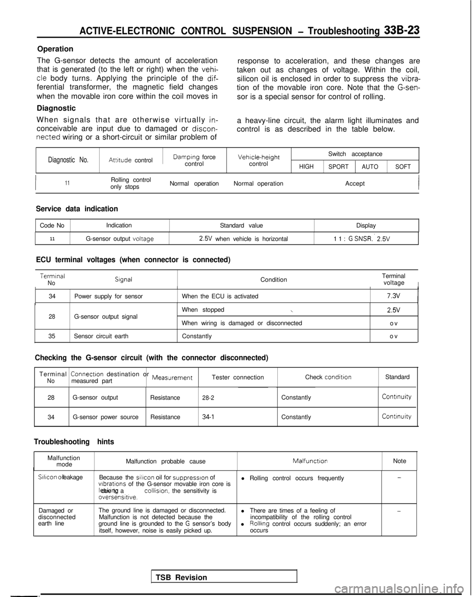
ACTIVE-ELECTRONIC CONTROL SUSPENSION - Troubleshooting 33B-23
Operation
The G-sensor detects the amount of acceleration
that is generated (to the left or right) when the
vehi-
response to acceleration, and these changes are
cle body turns. Applying the principle of the dif-
taken out as changes of voltage. Within the coil,
ferential transformer, the magnetic field changes silicon oil is enclosed in order to suppress the vibra-
tion of the movable iron core. Note that the
G-sen-
when the movable iron core within the coil moves in
Diagnostic sor is a special sensor for control of rolling.
When signals that are otherwise virtually
in-
conceivable are input due to damaged or discon-
a heavy-line circuit, the alarm light illuminates and
control is as described in the table below.
netted wiring or a short-circuit or similar problem of
Diagnostic No.Attitude controlDamplng force
controlVehicle-heightcontrol Switch acceptanceHIGH
SPORT AUTO SOFT
I11Rolling control
only stops Normal operation
Normal operation Accept
Service data indication
Code NoIndication
Standard value Display
11G-sensor output voltage 2.5V
when vehicle is horizontal 11: G SNSR:
2.5V
ECU terminal voltages (when connector is connected)
Terminal
NoCondition
Terminal
voltageIII
34 Power supply for sensor When the ECU is activated7.3vI
28G-sensor output signal
35 Sensor circuit earth When stoppedi
When wiring is damaged or disconnected
Constantly 2.5V
ov
ov
TSB Revision
-.
Checking the G-sensor circuit (with the connector disconnected)
Terminal ConnectIon
destination or MeasurementNomeasured part Tester connection
Check conditionStandard
28 G-sensor output
Resistance
28-2ConstantlyContinuity
34G-sensor power source
Resistance34-1ConstantlyContinuity
Troubleshooting hints
Malfunction
mode Malfunction probable causeMatfunctIonNoteSilicon
oil leakage
Because the sillcon
oil for
suppresslon of
l Rolling control occurs frequently-
vlbratlons of the G-sensor movable iron core is leaktng due to a collision.
the sensitivity is
oversensitive.
Damaged or
disconnected
earth line The ground line is damaged or disconnected.
l-Malfunction is not detected because the There are times of a feeling of
ground line is grounded to the G sensor’s body incompatibility of the rolling control
l
itself, however, noise is easily picked up. Rolling
control occurs suddenly; an error
occurs
Page 966 of 1273
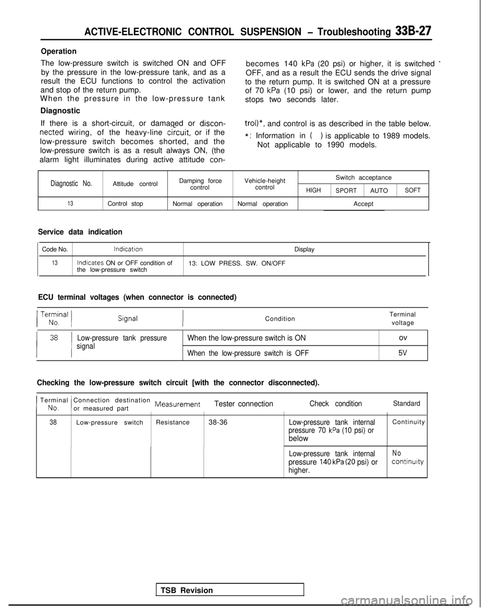
ACTIVE-ELECTRONIC CONTROL SUSPENSION - Troubleshooting 33B-27
Operation
The low-pressure switch is switched ON and OFFby the pressure in the low-pressure tank, and as a becomes 140 kPa (20 psi) or higher, it is switched *
result the ECU functions to control the activation
OFF, and as a result the ECU sends the drive signal
and stop of the return pump. to the return pump. It is switched ON at a pressure
When the pressure in the low-pressure tank of 70
kPa (10 psi) or lower, and the return pump
stops two seconds later.
Diagnostic
If there is a short-circuit, or damaged or discon-
netted wiring, of the heavy-line
circuit,
or if the
low-pressure switch becomes shorted, and the low-pressure switch is as a result always ON, (the
trol)“, and control is as described in the table below.
alarm light illuminates during active attitude
con-
*: Information in () is applicable to 1989 models.
Not applicable to 1990 models.
Diagnostic No.Attitude control Damping force
Vehicle-height Switch acceptance
control controlHIGH
SPORTAUTOSOFT
13Control stop Normal operationNormal operation Accept
Service data indication
Code No.lndicatron
Display
13Indicates
ON or OFF condition of
13: LOW PRESS. SW. ON/OFF
the low-pressure switch
ECU terminal voltages (when connector is connected)
TSB Revision
/ Te;;,nal 1Condition Terminal
voltage
Low-pressure tank pressure
signalWhen the low-pressure switch is ONov
When the low-pressure switch is OFF5v
Checking the low-pressure switch circuit [with the connector disconnecte\
d).
I No.
Terminal Connection destination Measurement
!or measured partTester connectionCheck conditionStandard
38Low-pressure switch Resistance
38-36Low-pressure tank internalContinuit
y
pressure 70 kPa (10 psi) or
below
Low-pressure tank internalNo
pressure 140 kPa (20 psi) orcontinuity
higher.
Page 974 of 1273
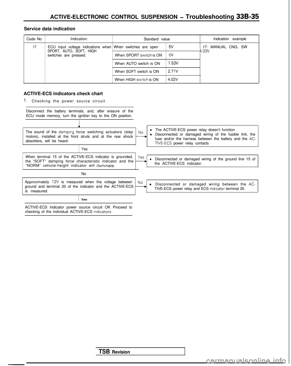
ACTIVE-ELECTRONIC CONTROL SUSPENSION - Troubleshooting 33B-35
Service data indication
Code No Indication
Standard value
17ECU input voltage indications when When switches are openSPORT, AUTO, SOFT, HIGH5V
switches are pressed.When SPORT switch
is ONOV
When AUTO switch is ON1.53v
When SOFT switch is ON 2.71V
When HIGH swrtch
is ON 4.02V
ACTIVE-ECS indicators check chart
1.Checking the power source circuit
Disconnect the battery terminals, and, after erasure of the
ECU mode memory, turn the ignition key to the ON position.
1
Indication example
17: MANUAL CNG. SW
4.03v
The sound of the damplng force switching actuators (steplNoThe ACTIVE-ECS power relay doesn’t function
motors), installed at the front struts and at the rear shock
--+l Disconnected or damaged wiring of the fusible link, the
absorbers, will be heard. fuse and/or the harness between the battery and the AC-TIVE-ECS power relay contacts
Yes
When terminal 15 of the ACTIVE-ECS indicator is grounded,yes
the “SOFT” damping force characteristic indicator and the -lDisconnected or damaged wiring of the ground line 15 of
“NORM” vehicle-height indicator will
illuminate.the ACTIVE-ECS indicator.
No
Approximately
12V is measured when the voltage betweenNo
ground and terminal 20 of the indicator and the ACTIVE-ECS --+l Disconnected or damaged wiring between the AC-
is measured. TIVE-ECS power relay and ECS Indicator
terminal 20.
I Yes
TSB Revision
-. ACTIVE-ECS Indicator power source circuit OK Proceed to
checking of the individual ACTIVE-ECS
lndlcators
Page 976 of 1273
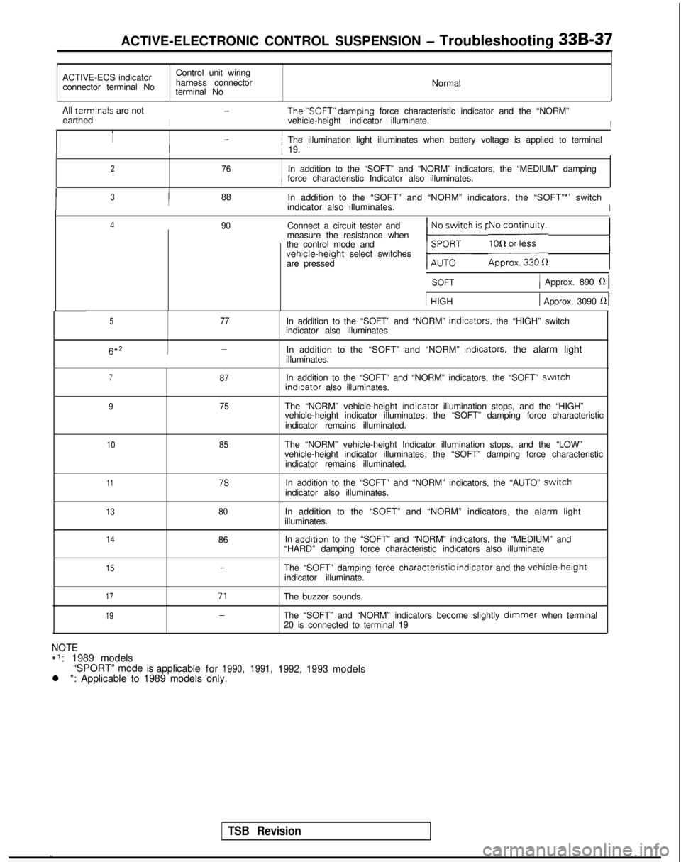
ACTIVE-ELECTRONIC CONTROL SUSPENSION - Troubleshooting 33B-37
r
ACTIVE-ECS indicator
Control unit wiring
connector terminal No harness connector
Normal
terminal No
All termrnals
are not
I
-The’SOFT” damprng
force characteristic indicator and the “NORM”
earthed vehicle-height indicator illuminate.
I
1-1 The illumination light illuminates when battery voltage is applied to t\
erminali 19.
276In addition to the “SOFT” and “NORM” indicators, the “MED\
IUM” dampingi force characteristic Indicator also illuminates.
I3/88
In addition to the “SOFT” and “NORM” indicators, the “SOF\
T”*’ switch
indicator also illuminates.
I
Ll90Connect a circuit tester and
measure the resistance when
the control mode and
vehicle-height select switches
are pressed
1 b;h is pressed.1 E;i;yi;;a 1
SOFT1 Approx. 890 fZ 1
/ HIGH1 Approx. 3090 121
577In addition to the “SOFT” and “NORM”
Indicators.
the “HIGH” switch
indicator also illuminates 6*2
-In addition to the “SOFT” and “NORM” Indicators, the alarm light
illuminates.
787In addition to the “SOFT” and “NORM” indicators, the “SOF\
T” swatch indrcator
also illuminates.
975The “NORM” vehicle-height rndicator
illumination stops, and the “HIGH”
vehicle-height indicator illuminates; the “SOFT” damping force cha\
racteristic
indicator remains illuminated.
1085The “NORM” vehicle-height Indicator illumination stops, and the “\
LOW”
vehicle-height indicator illuminates; the “SOFT” damping force cha\
racteristic indicator remains illuminated.
1178In addition to the “SOFT” and “NORM” indicators, the “AUT\
O” switchindicator also illuminates.
1380In addition to the “SOFT” and “NORM” indicators, the alarm l\
ight
illuminates.
1486 In addrtion
to the “SOFT” and “NORM” indicators, the “MEDIUM” and\
“HARD” damping force characteristic indicators also illuminate
15-The “SOFT” damping force characterrstic
indicator and the vehicle-herghtindicator illuminate.
17
1971
-
The buzzer sounds.
The “SOFT” and “NORM” indicators become slightly
dimmer when terminal
20 is connected to terminal 19
NOTE*l:1989 models
“SPORT” modeisapplicable for1990, 1991,1992,1993models
l *: Applicable to 1989 models only.
TSB Revision
Page 982 of 1273
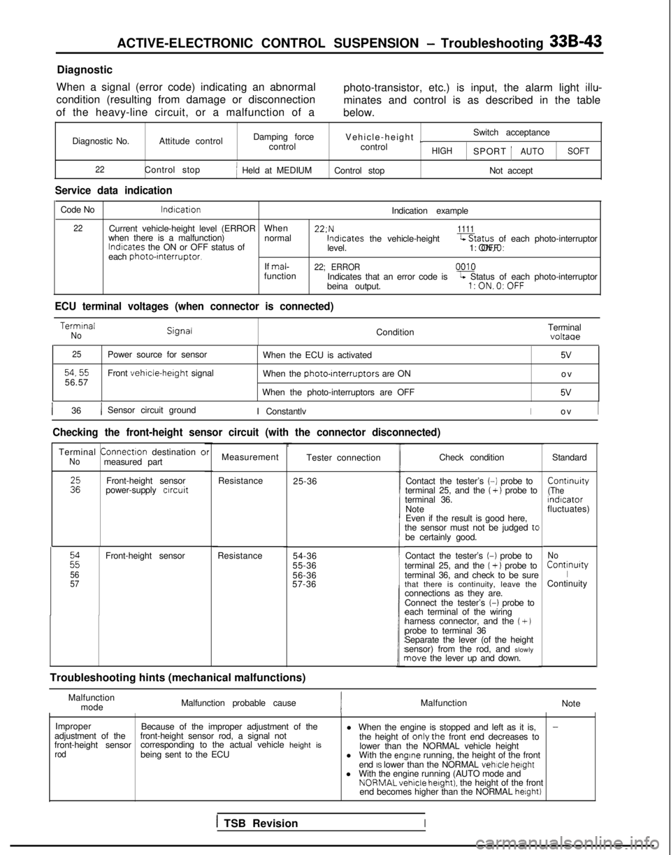
ACTIVE-ELECTRONIC CONTROL SUSPENSION - Troubleshooting 33B-43
Diagnostic
When a signal (error code) indicating an abnormal
condition (resulting from damage or disconnection
of the heavy-line circuit, or a malfunction of a photo-transistor, etc.) is input, the alarm light
illu-
minates and control is as described in the table
below.
Diagnostic No. Attitude control Damping force
Vehicle-height
~Switch acceptance
control control
HIGHSPORT 1AUTOSOFT
22
Control stopj Held at MEDIUM Control stop Not accept
Service data indication
Code No lndrcation
Indication example
22Current vehicle-height level (ERRORWhen 22:N1111when there is a malfunction)
normallndrcates
the ON or OFF status of lndtcates
the vehicle-height-Status of each photo-interruptor
level. 1: ON,O: OFF
each
photointerruptor.If mal-22; ERRORfunction
0010
Indicates that an error code isL Status of each photo-interruptor
beina output.l:ON.O:OFF
ECU terminal voltages (when connector is connected) Termrnal
NoCondition
Terminalvoltaae
25
54,5556.57Power source for sensor
Front vehicle-herght signal
When the ECU is activated
5V
When the photo-rnterruptors are ON
o
v
When the photo-interruptors are OFF
5V
1 36/ Sensor circuit ground I ConstantlvIo
v
I
Checking the front-height sensor circuit (with the connector disconnect\
ed)
Terminal
Connectron
destination cNomeasured part
:zFront-height sensor
power-supply crrcuit
22
56
57
Front-height sensor
Resistance
brMeasurement
Resistance 25-36Tester connection
54-36
55-36
56-36
57-36
t
Troubleshooting hints (mechanical malfunctions) Check condition
Standard
Contact the tester’s
(-1 probe to Contrnuity
terminal 25, and the ( + ) probe to(Theterminal 36.
rndrcator
Note fluctuates)
Even if the result is good here,
the sensor must not be judged
tcbe certainly good.
Contact the tester’s
(-1 probe to
terminal 25, and the (+ 1 probe to
terminal 36, and check to be sure
that there is continuity, leave the
connections as they are.
Connect the tester’s
(-1 probe to
each terminal of the wiring
harness connector, and the
(+ Jprobe to terminal 36
Separate the lever (of the height
sensor) from the rod, and slowly
nave the lever up and down.
No Continurty
IContinuity
Malfunction mode Malfunction probable cause
Malfunction
Note
Improper Because of the improper adjustment of the
-adjustment of the
front-height sensorfront-height sensor rod, a signal not
l When the engine is stopped and left as it is,
corresponding to the actual vehicle height is the height of onlythe front end decreases to
rodbeing sent to the ECU lower than the NORMAL vehicle height
l With the engrne running, the height of the front
end IS lower than the NORMAL vehicle
height
l With the engine running (AUTO mode and NORMALvehicle
hetght). the height of the front
end becomes higher than the NORMAL helght)
1 TSB RevisionI
Page 984 of 1273

ACTIVE-ELECTRONIC CONTROL SUSPENSION - Troubleshootina 33B-45
Diagnostic
When a signal (error code) indicating an abnormal condition (resulting from damage or disconnection
of the heavy-line circuit, or a malfunction of a photo-transistor, etc.) is input, the alarm light
illu-
minates and control is as described in the table
below.
Diagnostic No. Attitude control
23Control stop
Service data indication Damping force
control
Held at MEDIUM Vehicle-heigh
t
Switch acceptance
control
HIGH SPORT AUTOSOFT
Control stop
Not accept
Code No Indication
Indication example
23 Current vehicle-height level (ERROR When 23;N
1111when there is a malfunction)
normal
Indicates the ON or OFF status of Indicates the vehicle-height
levelL Status of each photo-interruptor
each photo-interruptor. 1: ON, 0. OFF
If mal-23; ERROR0010
function Indicates that an error code IS
being output.L Status of each photointerruptor1: ON, 0. OFF
ECU terminal voltages (when connector is connected) Terminal
No.Signal Condition
25 Power source for sensor
When the ECU is activated
61.62
63,64Front vehicle-height sIgnalWhen the photo-mterruptors are ON
When the photo-interruptors are OFF
36 Sensor circuit ground
Constantly Terminal
voltage
5v
o
v
5V
o
v
Checking the rear-height sensor circuit (with the connector disconnecte\
d)
rTerminal Connection destination or
M
easurement
No measured part Tester connection
Check conditionStandardRear-herght
sensor
power-supply circuit Resistance
25-36 Contact the tester’s (-) probe to
Continuity
terminal 25. and the
(+) probe to(Theterminal 36 indrcator
Note fluctuates)
Even if the result is good here,
the sensor must not be judged to be certainly good.
61
Es
Rear-height sensor A Resrstance
61-36No
F
Contact the tester’s (-)
probe to
62-36 terminal 25, and the ( +) probe toContinuity
63-36 terminal 36, and check to be sureIthat there is continuity; leave the Continuity
connections as they are.
Connect the tester’s
(-1 probe to
each termrnal
of the wiring
harness connector, and the
( +)probe to terminal 36. Separate the lever (of the height
sensor) from the rod, and slowly
move the lever up and down
64
- _. .
DResistance64-groundConstantly Continuity
1 roubleshooting hints (mechanical malfunctions)
Malfunctionmode Malfunction probable cause
MalfunctionNote
Improper Because of the improper adjustment of the l When the engine is stopped and left as it IS,
-adjustment of the
rear-height sensorrear-height sensor rod, a signal not
the height of only the rear end decreases to
rod correspondrng
to the actual vehicle height IS berng
sent to the ECU lower than the NORMAL vehicle height.lWith the engrne running, the height of the rear
end is lower than the NORMAL vehicle height
lWith the engine
running (AUTO mode and
NORMAL vehicle herght). the height of the rear
end becomes higher than the NORMAL height).
TSB Revision
Page 988 of 1273
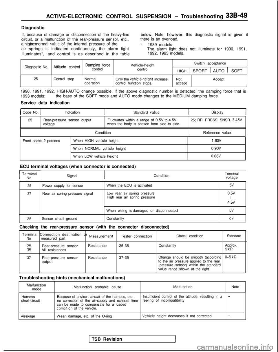
ACTIVE-ELECTRONIC CONTROL SUSPENSION - Troubleshooting 33B-49
Diagnostic
If, because of damage or disconnection of the heavy-line below. Note, however, this diagnostic signal is given if
circuit, or a malfunction of the rear-pressure sensor, etc., there is an overload.
a htgher than normal value of the internal pressure of the
l :1989 models
air springs is indicated continuously, the alarm light The alarm light does not illuminate for 1990, 1991,
illuminates*, and control is as described in the table 1992, 1993 models.
I1
Damping forceVehicle-heightSwitch acceptanceDiagnostic No.Attitude controlcontrol
control
HIGH 1 SPORT 1 AUTO 1 SOFT
25Control stopNormal
Only the vehicle-height
increase Not Accept
operation control function stops. accept
I
1990, 1991, 1992, HIGH-AUTO change possible. If the above diagnostic num\
ber is detected, the damping force that is
1993 models:the base of the SOFT mode and AUTO mode changes to the MEDIUM damping fo\
rce.
Service data indication
1 Code No. 1Indication
Standard valueDisplay
25Rear-pressure sensor output Fluctuates within a range of 0.5V
to 4.5V
25; RR. PRESS. SNSR. 2.45V
voltage when the body is shaken from side to side.
Condition
Reference value
Front seats: 2 persons When HIGH vehicle height
When NORMAL vehicle height
When LOW vehicle
height
1.6OV
0.9ov 0.86V
ECU terminal voltages (when connector is connected) ConditionTerminal
voltage
25Power supply for sensor
37Rear air spring pressure signal When the ECU is activated
Low rear air spring pressure
High rear air spring pressure
5v
0.5vI
4.5v
When wiring IS damaged or disconnected5v
35 Sensor circuit ground
Constantly o
v
Checking the rear-pressure sensor (with the connector disconnected)
Terminal Connection destination or MeasurementNomeasured part
Tester connection
Check condition
Standard
ERear-pressure sensorResistance
25-35 Constantly Approx.
All resistances 5 kll
37Rear-pressure sensor
Resistance
37-35 Change should be smooth (accordingO-5 klloutput to the air pressure applied to the rear
-pressure sensor) within the standard
value range shown at the right
Troubleshooting hints (mechanical malfunctions) Malfunctionmode Malfunction probable cause
Malfunction
Note
Harness
short-circuit Because of a short-circurt
of the harness, etc , Insufficient control of the attitude, resulting in a
-no correction of the air-supply and exhaust time feeling of incompatibility
can be made to compensate for a loaded
condition of the vehicle. Air leakage
Wear, damage, etc. of the O-ring
Vehicle height decreases if not corrected-
TSB Revision