1989 MITSUBISHI GALANT differential
[x] Cancel search: differentialPage 20 of 1273
00-l 8GENERAL - Towing and Hoisting
SAFETY PRECAUTIONS
The following precautions should be taken when towing thevehicle.
1.DO NOT LIFT OR TOW THE VEHICLE BY ATTACHING TO
OR WRAPPING AROUND THE BUMPER.
2. Any loose or protruding parts of damaged vehicle such as hoods, doors, fenders, trim, etc., should be secured prior to
moving the vehicle.
3.Operator should refrain from going under a vehicle while it
is lifted by the towing equipment, unless the vehicle in
adequately supported by satefy stands.
4. Never allow passengers to ride in a towed vehicle. 5. State and local rules and regulations must be followed when towing a vehicle.
Refer to the section “Special Handling Instructions for AWD
Models”.
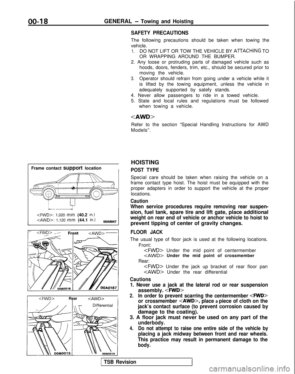
Frame contact support location
I
HOISTING
POST TYPE
Special care should be taken when raising the vehicle on a
frame contact type hoist. The hoist must be equipped with the
proper adapters in order to support the vehicle at the proper
locations.
Caution
When service procedures require removing rear suspen-
sion, fuel tank, spare tire and lift gate, place additional
weight on rear end of vehicle or anchor vehicle to hoist to
prevent tipping of center of gravity changes.
FLOOR JACK
The usual type of floor jack is used at the following locations.
Front:
tAWD> Under the mid point of crossmember
Rear:
Cautions
1. Never use a jack at the lateral rod or rear suspension
assembly.
2.In order to prevent scarring the centermember
or crossmember
place a piece of cloth on the
jack’s contact surface (to prevent corrosion caused by
damage to the coating).
3. A floor jack must never be used on any part of the
underbody.
4.Do not attempt to raise one entire side of the vehicle by
placing a jack midway between front and rear wheels.
This practice may result in permanent damage to the
body.
TSB RevisionI
Page 49 of 1273
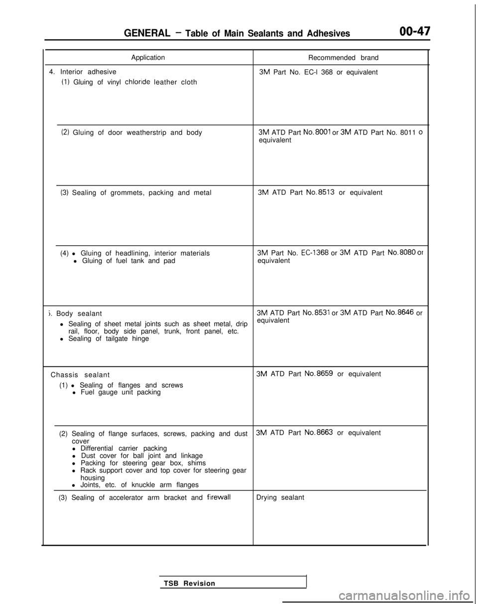
GENERAL - Table of Main Sealants and Adhesives00-47
Application
4. Interior adhesive
(1) Gluing of vinyl chloride
leather cloth Recommended brand 3M
Part No. EC-l 368 or equivalent
(2) Gluing of door weatherstrip and body 3M
ATD Part No.8001 or 3M
ATD Part No. 8011 oequivalent
(3) Sealing of grommets, packing and metal 3M
ATD Part No.8513
or equivalent
(4) l Gluing of headlining, interior materials l Gluing of fuel tank and pad 3M
Part No.
EC-1368 or 3M
ATD Part No.8080
01equivalent
j. Body sealant 3M
ATD Part No.8531 or 3M
ATD Part No.8646
or
l Sealing of sheet metal joints such as sheet metal, drip equivalent
rail, floor, body side panel, trunk, front panel, etc.
l Sealing of tailgate hinge
Chassis sealant (1) l Sealing of flanges and screws l Fuel gauge unit packing 3M
ATD Part No.8659
or equivalent
(2) Sealing of flange surfaces, screws, packing and dust 3M
ATD Part No.8663
or equivalent
cover l Differential carrier packing
l Dust cover for ball joint and linkage
l Packing for steering gear box, shims
l Rack support cover and top cover for steering gear
housing
l Joints, etc. of knuckle arm flanges
(3) Sealing of accelerator arm bracket and
firewallDrying sealant
TSB Revision
Page 50 of 1273
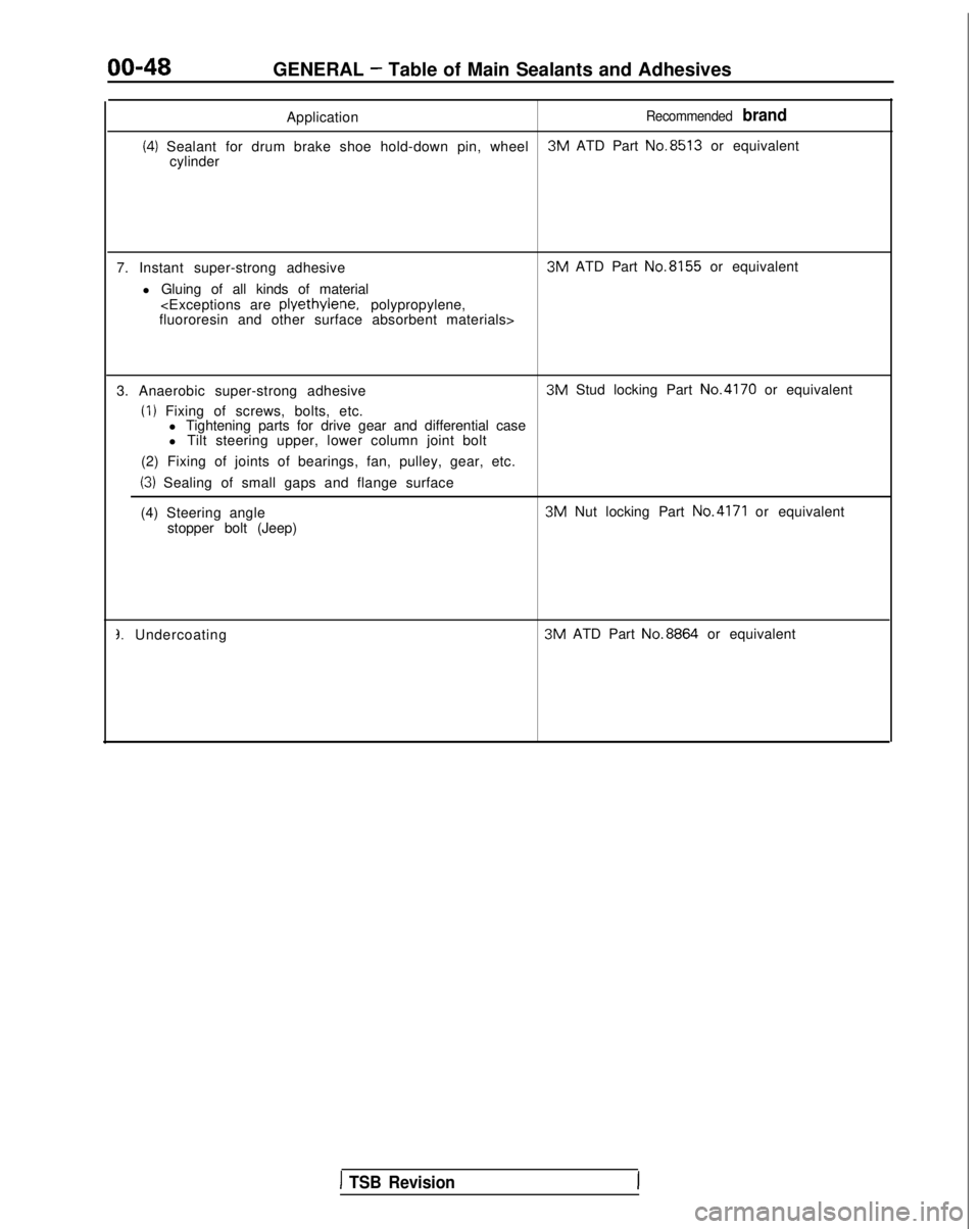
00-48GENERAL - Table of Main Sealants and Adhesives
Application
Recommended brand
(4) Sealant for drum brake shoe hold-down pin, wheel 3M
ATD Part No.8513
or equivalent
cylinder
7. Instant super-strong adhesive l Gluing of all kinds of material 3M
ATD Part No.8155
or equivalent
fluororesin and other surface absorbent materials>
3. Anaerobic super-strong adhesive
(I) Fixing of screws, bolts, etc. 3M
Stud locking Part No.4170
or equivalent
l Tightening parts for drive gear and differential case
l Tilt steering upper, lower column joint bolt
(2) Fixing of joints of bearings, fan, pulley, gear, etc.
(3) Sealing of small gaps and flange surface
(4) Steering angle 3M
Nut locking Part
No.4171 or equivalent
stopper bolt (Jeep)
3. Undercoating 3M
ATD Part No.8864
or equivalent
1 TSB Revision
Page 667 of 1273
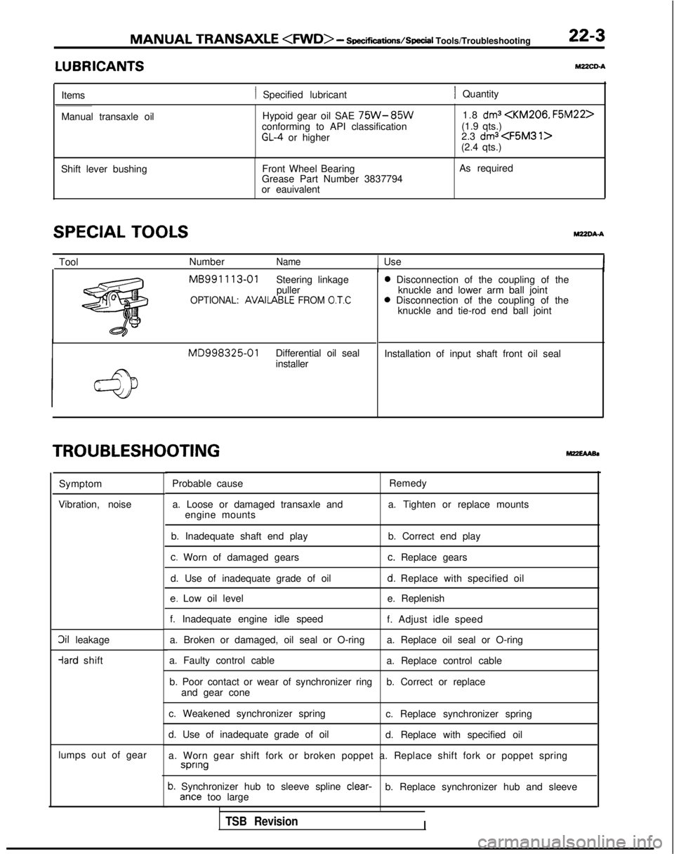
MANUAL TRANSAXLE
- Soec~cations/SpeciI
Tools/Troubleshooting 22-3
LUBRICANTSYZZCD-A
Items1 Specified lubricant1 Quantity
Manual transaxle oil Hypoid gear oil SAE
75W-85Wconforming to API classificationGL-4 or higher1.8
dma
(1.9 qts.)
2.3 dma
Shift lever bushing Front Wheel Bearing
Grease Part Number 3837794
or eauivalent As required
SPECIAL TOOLSWDA-A
Tool
NumberName1 UseI MB991
113-01
Steering linkage
puller
OPTIONAL: AVAIlABLE FROM 0.T.C
MD998325-01Differential oil seal
installer 0
Disconnection of the coupling of the
knuckle and lower arm ball joint 0
Disconnection of the coupling of the
knuckle and tie-rod end ball joint
Installation of input shaft front oil seal
TROUBLESHOOTING
Symptom
Vibration, noise
3il leakage -lard
shift
lumps out of gear Probable cause
Remedy
a. Loose or damaged transaxle and a. Tighten or replace mounts
engine mounts
b. Inadequate shaft end play b. Correct end play
c. Worn of damaged gearsc. Replace gears
d. Use of inadequate grade of oil
d. Replace with specified oil
e. Low oil level e. Replenish
f. Inadequate engine idle speed f. Adjust idle speed
a. Broken or damaged, oil seal or O-ring a. Replace oil seal or O-ring
a. Faulty control cable a. Replace control cable
b. Poor contact or wear of synchronizer ring b. Correct or replace
and gear cone
c. Weakened synchronizer spring c. Replace synchronizer spring
d. Use of inadequate grade of oil d. Replace with specified oil
a. Worn gear shift fork or broken poppet a. Replace shift fork or poppet\
spring spnng
b. Synchronizer hub to sleeve spline
clear-
b. Replace synchronizer hub and sleeveante too large
TSB RevisionI
Page 680 of 1273
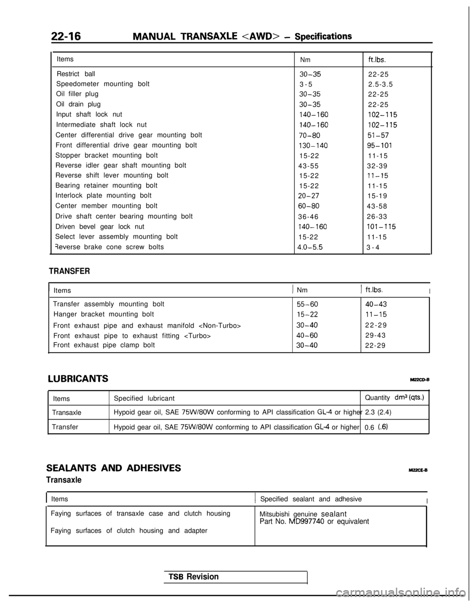
22-16MANUAL TRANSAXLE
ItemsNmftlbs.
Restrict ball30-3522-25
Speedometer mounting bolt 3-
5
2.5-3.5
Oil filler plug
30-3522-25
Oil drain plug
30-3522-25
Input shaft lock nut
140-160102-115
Intermediate shaft lock nut140-160102-115
Center differential drive gear mounting bolt70-8051-57
Front differential drive gear mounting bolt130-14095-101
Stopper bracket mounting bolt 15-2211-15
Reverse idler gear shaft mounting bolt 43-5532-39
Reverse shift lever mounting bolt 15-22
71-15
Bearing retainer mounting bolt15-2211-15
Interlock plate mounting bolt
20-2715-19
Center member mounting bolt
60-8043-58
Drive shaft center bearing mounting bolt 36-4626-33
Driven bevel gear lock nut
740-160lOl-‘1’15
Select lever assembly mounting bolt 15-2211-15qeverse
brake cone screw bolts
4.0-5.53-
4
TRANSFER
1
Items
) Nm) ft.lbs.I
Transfer assembly mounting bolt55-6040-43
Hanger bracket mounting bolt15-2211-15
Front exhaust pipe and exhaust manifold
9
Front exhaust pipe to exhaust fitting
40-6029-43
Front exhaust pipe clamp bolt
30-4022-29
LUBRICANTSMz2co-B
Items
Transaxle
Transfer Specified lubricant
Quantity drnj
(qts.)
Hypoid gear oil, SAE 75W/8OW conforming to API classification GL-4 or higher 2.3 (2.4)
Hypoid gear oil, SAE
75W/8OW conforming to API classification GL-4 or higher 0.6 t.6)
SEALANTS AND ADHESIVES
Transaxle
M22cE.B
IItems1 Specified sealant and adhesiveI
Faying surfaces of transaxle case and clutch housing
Mitsubishi genuine sealant
Part No. MD997740 or equivalent
Faying surfaces of clutch housing and adapter
TSB Revision
Page 681 of 1273
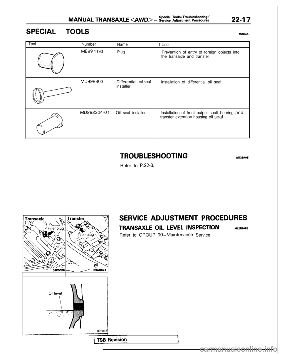
MANUAL TRANSAXLE
SPECIAL TOOLSMZSDA-
ToolNumberNameI Use
w
MB99
1193
r
PlugPrevention of entry of foreign objects into
the transaxle and transfer
L
MD998803Differential 011 sealInstallation of differential oil seal
t&-
installer
MD998304-0 1Oil seal installer Installation of front output shaft bearing and
transfer extention
housing oil seal
TROUBLESHOOTING
Refer to P.22-3.
M22EAAE
SERVICE ADJUSTMENT PROCEDURES
TRANSAXLE OIL LEVEL INSPECTIONm
Refer to GROUP 00-Maintenance Service.
\ //’ 09AOO24
Page 816 of 1273
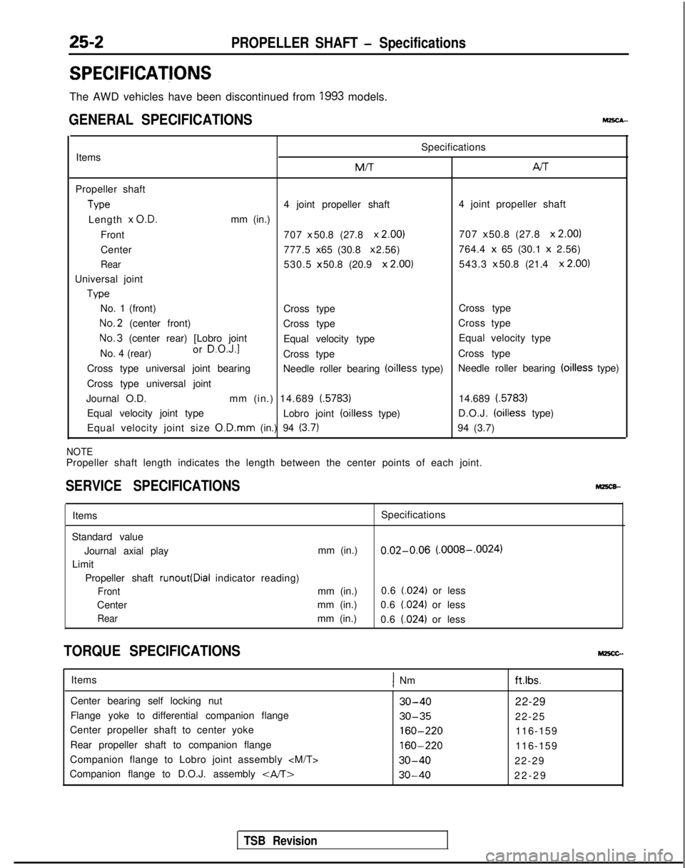
25-2PROPELLER SHAFT - Specifications
SPEClFlCATjONS
The AWD vehicles have been discontinued from 1993 models.
GENERAL SPECIFICATIONSM2scA-
Specifications
Items M/T
Arr
Propeller shaft
Type
4 joint propeller shaft
4 joint propeller shaft
Length x
O.D.mm (in.)
Front 707 x 50.8 (27.8
x 2.00)707 x 50.8 (27.8 x
2.00)
Center 777.5 x 65 (30.8 x 2.56)
764.4 x
65 (30.1 x
2.56)
Rear530.5 x 50.8 (20.9 x
2.00)543.3 x 50.8 (21.4 x
2.00)
Universal joint Type
No. 1 (front) Cross typeCross typeNo.2
(center front)
Cross type Cross typeNo.3
(center rear) [Lobro joint
Equal velocity type Equal velocity type
No. 4 (rear) or
D.O.J.1Cross type
Cross type
Cross type universal joint bearing Needle roller bearing (oilless
type) Needle roller bearing (oilless
type)
Cross type universal joint
Journal O.D. mm (in.) 14.689 l.5783)
14.689 i.5783)
Equal velocity joint type Lobro joint
(oilless type)D.O.J. (oilless
type)
Equal velocity joint size O.D.mm
(in.) 94
(3.7)94 (3.7)
NOTEPropeller shaft length indicates the length between the center points of\
each joint.
SERVICE SPECIFICATIONSMz5c&-
Items Specifications
Standard value Journal axial play mm (in.)
0.02-0.06 (.0008-.0024)
Limit
Propeller shaft runout(Dial
indicator reading)
Frontmm (in.) 0.6 t.024) or less
Center mm (in.)
0.6
t.024) or less
Rearmm (in.)
0.6 (.024) or less
TORQUE SPECIFICATIONSMzxc-
Items1 Nm
Center bearing self locking nut
30-4022-29
Flange yoke to differential companion flange
30-3522-25
Center propeller shaft to center yoke
160-220116-159
Rear propeller shaft to companion flange
160-220116-159
Companion flange to Lobro joint assembly
30-4022-29
Companion flange to D.O.J. assembly
30-4022-2
9
ft.lbs.
TSB Revision
Page 818 of 1273
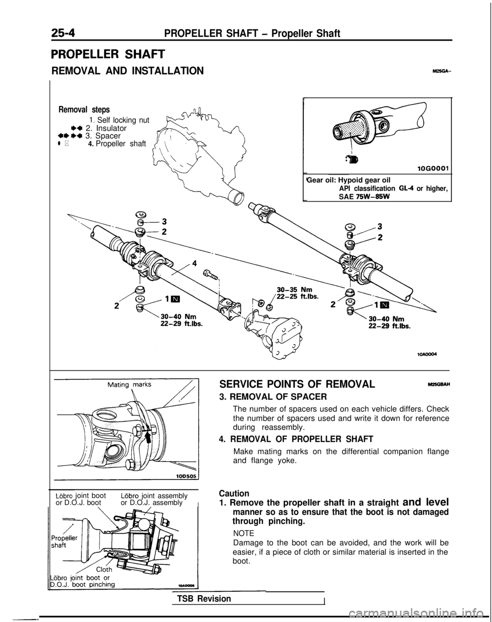
25-4PROPELLER SHAFT - Propeller Shaft
PROPELLER SHAFT
REMOVAL AND INSTALLATION
Removal steps
1. Self locking nut
** 2. Insulator***a 3. Spacerl *4.
Propeller shaft
r
:&I
lOGO
Gear oil: Hypoid gear oil
API classification GL-4 or higher,
SAE 75W-85W
SERVICE POINTS OF REMOVALMEGBAH
3. REMOVAL OF SPACER
The number of spacers used on each vehicle differs. Checkthe number of spacers used and write it down for reference
during reassembly.
4. REMOVAL OF PROPELLER SHAFT
Make mating marks on the differential companion flange
and flange yoke.
Lijbro joint bootL6bro joint assembly
or D.O.J. boot or D.O.J. assembly
I
Caution
1. Remove the propeller shaft in a straight and level
manner so as to ensure that the boot is not damaged
through pinching.
NOTE
Damage to the boot can be avoided, and the work will be
easier, if a piece of cloth or similar material is inserted in the
boot.
TSB RevisionI