Page 159 of 1273

FUEL SYSTEM - Troubleshooting 13-17
\ I\-\\\\\\6FUO807
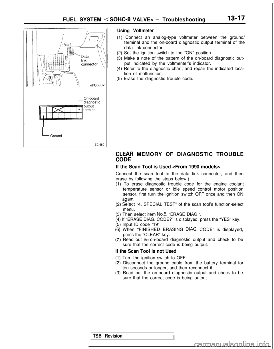
Using Voltmeter
(1) Connect an analog-type voltmeter between the ground/
terminal and the on-board diagnostic output terminal of the
data link connector.
(2) Set the ignition switch to the “ON” position.
(3) Make a note of the pattern of the on-board diagnostic out- put indicated by the voltmenter’s indicator.
(4) Refer to the diagnostic chart, and repair the indicated loca- tion of malfunction.
(5) Erase the diagnostic trouble code.
On-board
diagnostic
output
terminal
LGround
EbLbtR MEMORY OF DIAGNOSTIC TROUBLE
If the Scan Tool is Used
Connect the scan tool to the data link connector, and then
erase by following the steps below.)
(1) To erase diagnostic trouble code for the engine coolant
temperature sensor or idle speed control motor positionsensor, first turn the ignition switch OFF once and then ON
(2) EE?$t
“4. SPECIAL TEST” of the scan tool’s function-select
menu.
(3) Then select item No.5, “ERASE DIAG.“.
(4) If “ERASE DIAG. CODE?” is displayed, press the “YES” k\
ey.
(5) Input ID code “19”.
(6) When “FINISHED ERASING DIAG. CODE” is displayed,> Ipress the “CLEAR” key.
(7) Read out the on-board diagnostic output and check to be
sure that the correct code is being output.
If the Scan Tool is not Used
(1) Turn the ignition switch to OFF.
(2) Disconnect the ground cable from the battery terminal forten seconds or longer, and then reconnect it.
(3) Read out the on-board diagnostic output and check to be
sure that the correct code is being output.
TSB RevisionI
Page 183 of 1273

FUEL SYSTEM - On-Vehicule Inspection of MFI Components13-41
Ciaarette
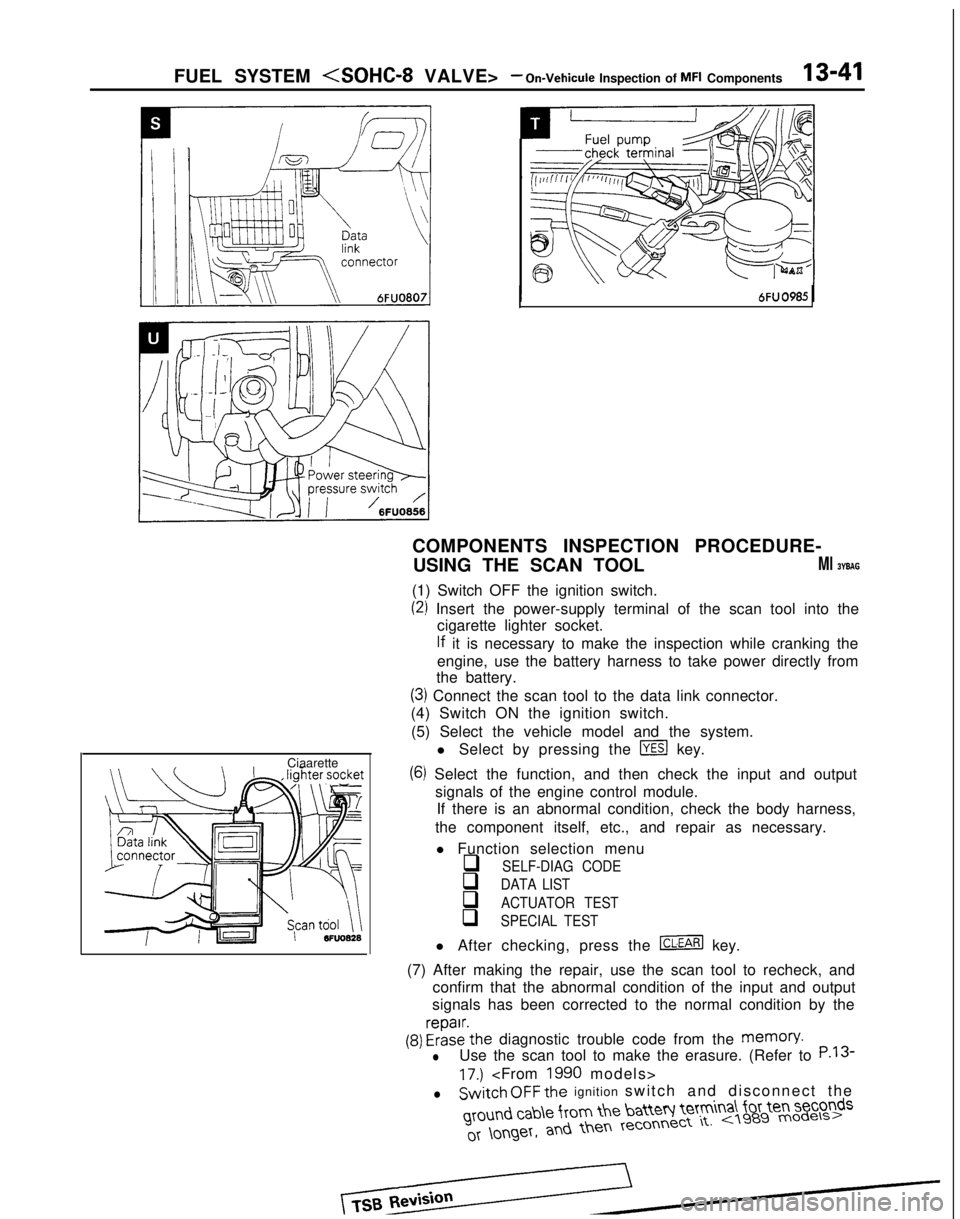
COMPONENTS INSPECTION PROCEDURE-
USING THE SCAN TOOL
Ml BYBAG
(1) Switch OFF the ignition switch.
(2) Insert the power-supply terminal of the scan tool into the cigarette lighter socket.
lf it is necessary to make the inspection while cranking the
engine, use the battery harness to take power directly from
the battery.
(3) Connect the scan tool to the data link connector.
(4) Switch ON the ignition switch.
(5) Select the vehicle model and the system. l Select by pressing the
m key.
(6) Select the function, and then check the input and outputsignals of the engine control module.If there is an abnormal condition, check the body harness,
the component itself, etc., and repair as necessary.
l Function selection menu
q SELF-DIAG CODE
q DATA LIST
q ACTUATOR TEST
q SPECIAL TEST
l After checking, press the m key.
(7) After making the repair, use the scan tool to recheck, and confirm that the abnormal condition of the input and output
signals has been corrected to the normal condition by the
(9) FrizE’the diagnostic trouble code from the memory.
lUse the scan tool to make the erasure. (Refer to P.13
17.)
lSwitch OFF the ignition switch and disconnect the ground
cab\e from the batteq Ie’tm
a\ for ten seconds
Page 505 of 1273

AUTO-CRUISE CONTROL SYSTEM - Troubleshooting13-363
With scan toolri++, lighter ;
03A0258
TSB Revision
After the diagnostic trouble codes in the memory are
erased, if (when the power supply of the electronic controlunit is switched ON once again) the power supply of the
electronic control unit is normal, the on-board diagnostic
output code display will be as below, regardless of
whether the system condition is normal or not.
@ If a scan tool is used: “NORMAL!!” will be displayed.
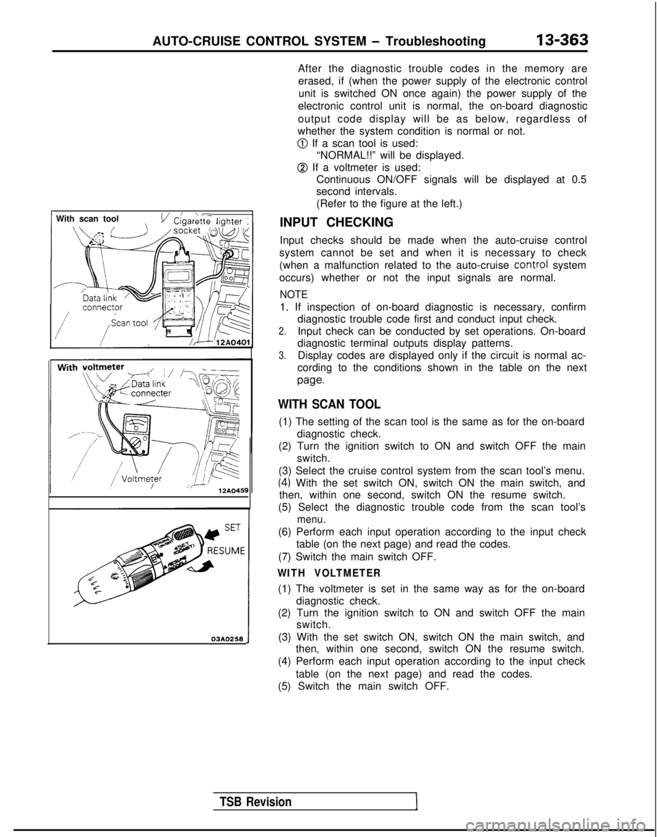
@ If a voltmeter is used:Continuous ON/OFF signals will be displayed at 0.5
second intervals.
(Refer to the figure at the left.)
INPUT CHECKING
Input checks should be made when the auto-cruise control
system cannot be set and when it is necessary to check
(when a malfunction related to the auto-cruise
contra! system
occurs) whether or not the input signals are normal.
NOTE
1. If inspection of on-board diagnostic is necessary, confirm diagnostic trouble code first and conduct input check.
2.Input check can be conducted by set operations. On-board
diagnostic terminal outputs display patterns.
3.Display codes are displayed only if the circuit is normal ac-
cording to the conditions shown in the table on the next
paw
WITH SCAN TOOL
(1) The setting of the scan tool is the same as for the on-board diagnostic check.
(2) Turn the ignition switch to ON and switch OFF the main switch.
(3) Select the cruise control system from the scan tool’s menu.
(4) With the set switch ON, switch ON the main switch, and
then, within one second, switch ON the resume switch.
(5) Select the diagnostic trouble code from the scan tool’s
menu.
(6) Perform each input operation according to the input check table (on the next page) and read the codes.
(7) Switch the main switch OFF.
WITH VOLTMETER
(1) The voltmeter is set in the same way as for the on-board diagnostic check.
(2) Turn the ignition switch to ON and switch OFF the main switch.
(3) With the set switch ON, switch ON the main switch, and then, within one second, switch ON the resume switch.
(4) Perform each input operation according to the input check
table (on the next page) and read the codes.
(5) Switch the main switch OFF.