1989 MITSUBISHI GALANT stop start
[x] Cancel search: stop startPage 43 of 1273
GENERAL - Maintenance Service00-41
-1
6COOO9
L!6COO39
OlR0344
6. DRIVE BELT (For Water Pump and
Generator) (Inspect for tension)
MOOSBBN
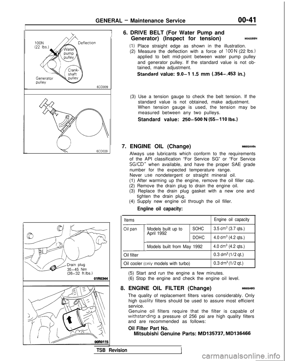
(1) Place straight edge as shown in the illustration.
(2) Measure the deflection with a force of
100 N (22 Ibs.)
applied to belt mid-point between water pump pulley
and generator pulley. If the standard value is not ob-
tained, make adjustment.
Standard value: 9.0-l 1.5 mm (.354-.453
in.)
(3) Use a tension gauge to check the belt tension. If the standard value is not obtained, make adjustment.
When tension gauge is used, the tension may be
measured between any two pulleys.
Standard value:
250-500 N (55-110
Ibs.)
7. ENGINE OIL (Change)MOOSAABc
Always use lubricants which conform to the requirements
of the API classification “For Service SG” or “For Service SG/CD”
when available, and have the proper SAE grade
number for the expected temperature range.
Never
Lose nondetergent or straight mineral oil.
(1) After warming up the engine, remove the oil filler cap.
(2) Remove the drain plug to drain the engine oil. (3) Replace the drain plug gasket with a new one and
tighten the drain plug.
(4) Supply new engine oil through the oil filler.
Engiine oil capacity:
Items Engine oil capacity
Oil pan
1
Models built up toSOHC3.5 dm3 (3.7 qts.)
April 1992DOHC4.0 dm3 (4.2 qts.)
Models built from May 19924.0 dm3 (4.2 qts.)
Oil filter 0.3 dm3 (l/2 qt.)
Oil cooler
(clnly models with turbo) 0.3 dm3 (I/2 qt.)
(5) Start and run the engine a few minutes.
(6) Stop the engine and check the engine oil level.
8. ENGINE OIL FILTER (Change)
MOOSABG
The quality of replacement filters varies considerably. Only high
quatlity filters should be used to assure most efficient
service. Genuine oil filters require that the filter is capable of
withstarlding a pressure of 256 psi are high quality filters
and are recommended as follows:
Oil Filter Part No.
Mitsubishi Genuine Parts: MD135737,
MD136466
TSB Revision
Page 44 of 1273
00-42GENERAL -Maintenance Service
ENGINE OIL FILTER SELECTION
This vehicle is equipped with a full-flow, throw-away oilfilter.
The same type of replacement filter is recommended as a replacement filter for this vehicle. It is possible, particularily
in cold weather, that this vehicle may develop high oil
pressure for a short duration. You should be sure that any replacement filter used on this vehicle is a high-quality filter
and is capable of withstanding a pressure of 256 psi (manufacturer’s specifications) to avoid filter and engine
damage. The following is a high-quality filter and is strongly
recommended for use on this vehicle
: Mitsubishi Engine
Oil Filter Part No. MD1 35737 or MD1 36466.
Any replacement oil filter should be installed in accordance
with the oil filter manufacturer’s installation instructions. (1) Remove the engine oil filler cap.
(2) Remove the engine oil drain plug, and drain out the
engine oil.
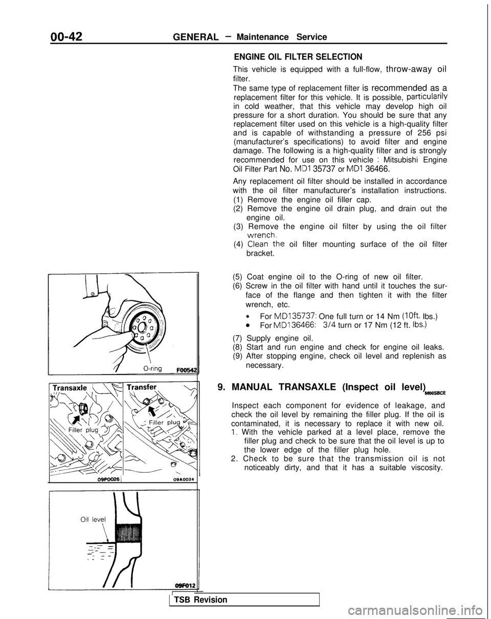
(3) Remove the engine oil filter by using the oil filter
(4)
GLr!he oil filter mounting surface of the oil filter
bracket.
OSPOO26 1 09A.0024(5) Coat engine oil to the O-ring of new oil filter.
(6) Screw in the oil filter with hand until it touches the sur-
face of the flange and then tighten it with the filter
wrench, etc.
l For MD135737:
One full turn or 14 Nm
(loft. Ibs.)0For MD136466:3/4 turn or 17 Nm (12 ft. Ibs.)
(7) Supply engine oil.
(8) Start and run engine and check for engine oil leaks.
(9) After stopping engine, check oil level and replenish as
necessary.
9. MANUAL TRANSAXLE (Inspect oil level)
MOO66CE
Inspect each component for evidence of leakage, and
check the oil level by remaining the filler plug. If the oil is
contaminated, it is necessary to replace it with new oil.
I. With the vehicle parked at a level place, remove the filler plug and check to be sure that the oil level is up to
the lower edge of the filler plug hole.
2. Check to be sure that the transmission oil is not noticeably dirty, and that it has a suitable viscosity.
TSB Revision
Page 57 of 1273
ENGINE
OlR0340
1
SERVICE ADJUSTMENT PROCEDU$$o
ENGINE OIL CHECK
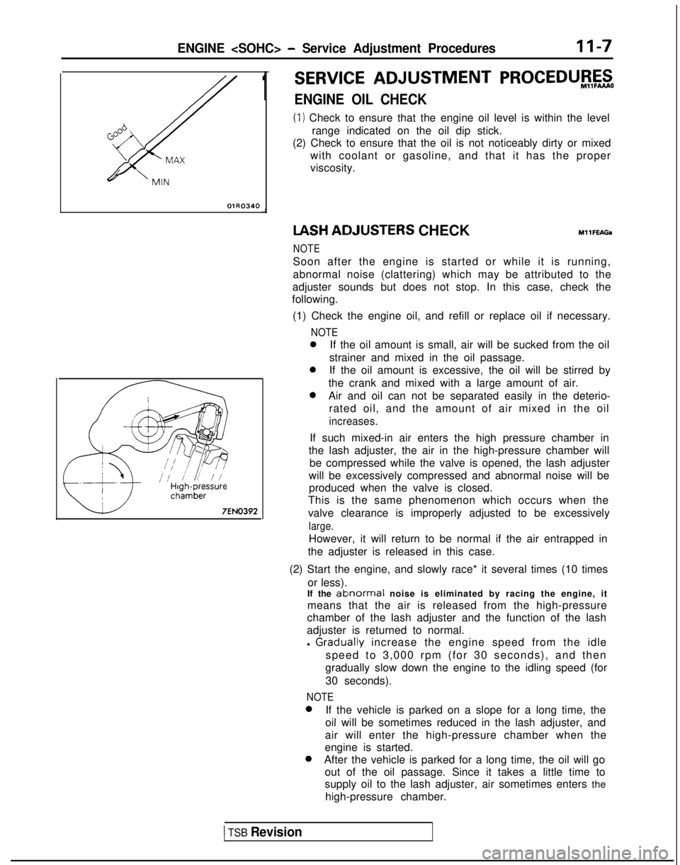
(1) Check to ensure that the engine oil level is within the level
range indicated on the oil dip stick.
(2) Check to ensure that the oil is not noticeably dirty or mixed
with coolant or gasoline, and that it has the proper
viscosity. IASH
ACIJUSTERS CHECKMllFEAGa
NOTE
Soon after the engine is started or while it is running,
abnormal noise (clattering) which may be attributed to the
adjuster sounds but does not stop. In this case, check the
following.
(1) Check the engine oil, and refill or replace oil if necessary.
NOTE
0If the oil amount is small, air will be sucked from the oil
strainer and mixed in the oil passage.
0If the oil amount is excessive, the oil will be stirred by
the crank and mixed with a large amount of air.
0Air and oil can not be separated easily in the deterio- rated oil, and the amount of air mixed in the oil
increases.
If such mixed-in air enters the high pressure chamber in
the lash adjuster, the air in the high-pressure chamber will be compressed while the valve is opened, the lash adjuster
will be excessively compressed and abnormal noise will be produced when the valve is closed.
This is the same phenomenon which occurs when the
valve clearance is improperly adjusted to be excessively
large.
However, it will return to be normal if the air entrapped in
the adjuster is released in this case.
(2) Start the engine, and slowly race* it several times (10 times or less).
If the
ablnormal noise is eliminated by racing the engine, it
means that the air is released from the high-pressure
chamber of the lash adjuster and the function of the lash
adjuster is returned to normal.
l
Graclually increase the engine speed from the idle
speed to 3,000 rpm (for 30 seconds), and then
gradually slow down the engine to the idling speed (for
30 seconds).
NOTE 0
If the vehicle is parked on a slope for a long time, the
oil will be sometimes reduced in the lash adjuster, and
air will enter the high-pressure chamber when the
engine is started. 0
After the vehicle is parked for a long time, the oil will go
out of the oil passage. Since it takes a little time to
supply oil to the lash adjuster, air sometimes enters the
high-pressure chamber.
1 TSB Revision
Page 58 of 1273
II-8ENGINE
8 VALVE
W Tlmlng belt side
il6
16
727
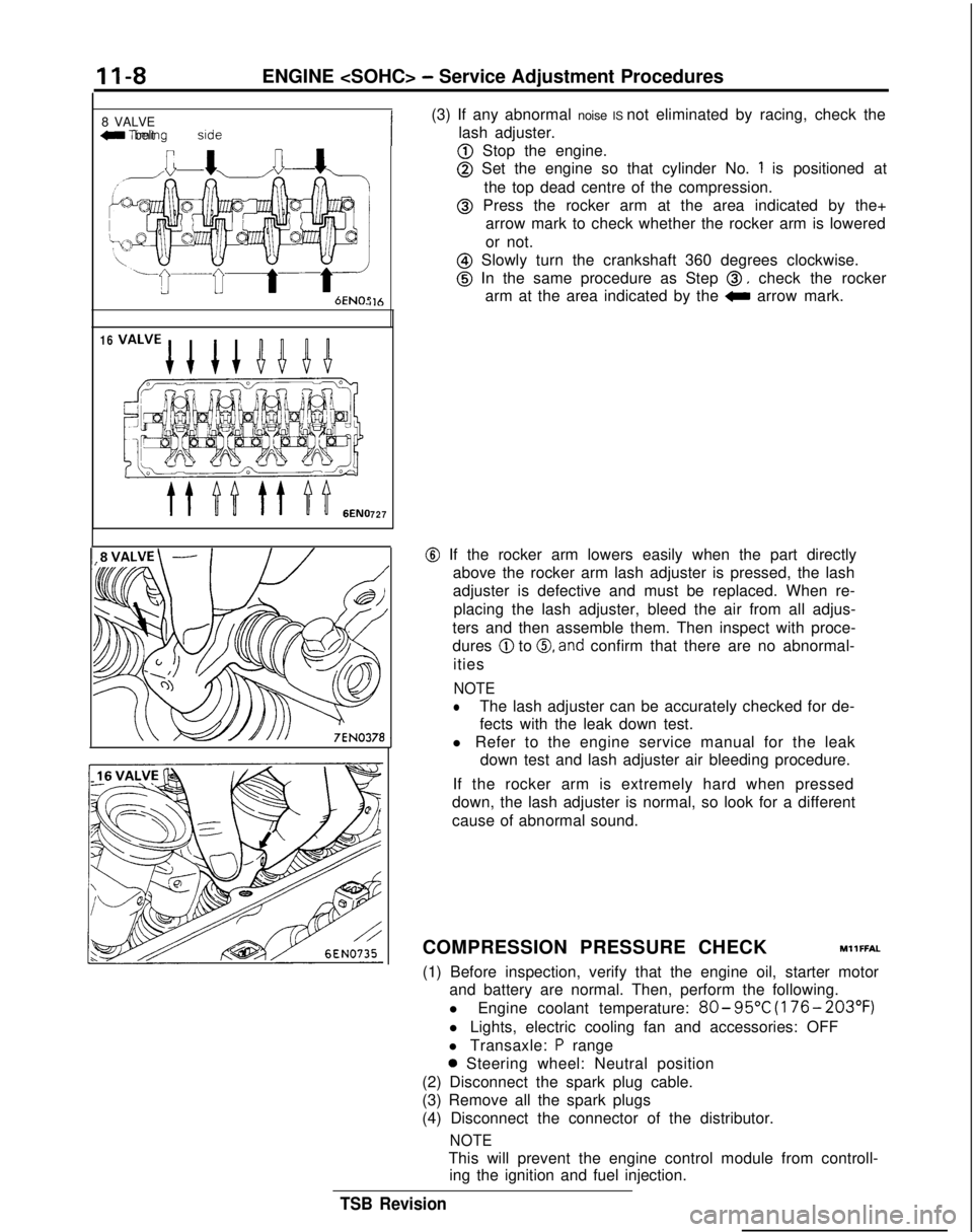
(3) If any abnormal noise IS not eliminated by racing, check the
lash adjuster.
@ Stop the engine.
@ Set the engine so that cylinder No. 1 is positioned at
the top dead centre of the compression.
@ Press the rocker arm at the area indicated by the+ arrow mark to check whether the rocker arm is lowered
or not.
@ Slowly turn the crankshaft 360 degrees clockwise.
@ In the same procedure as Step 0, check the rocker
arm at the area indicated by the
0 arrow mark.
@ If the rocker arm lowers easily when the part directly
above the rocker arm lash adjuster is pressed, the lash
adjuster is defective and must be replaced. When re-
placing the lash adjuster, bleed the air from all adjus-
ters and then assemble them. Then inspect with proce-
dures
@ to 0, and confirm that there are no abnormal-
ities
NOTE
lThe lash adjuster can be accurately checked for de-
fects with the leak down test.
l Refer to the engine service manual for the leak down test and lash adjuster air bleeding procedure.
If the rocker arm is extremely hard when pressed
down, the lash adjuster is normal, so look for a different
cause of abnormal sound.
COMPRESSION PRESSURE CHECK
MllFFAL
(1) Before inspection, verify that the engine oil, starter motor and battery are normal. Then, perform the following.
l Engine coolant temperature:
80- 95°C
(176- 203°F)
l Lights, electric cooling fan and accessories: OFF
l Transaxle:
P range
0 Steering wheel: Neutral position
(2) Disconnect the spark plug cable.
(3) Remove all the spark plugs
(4) Disconnect the connector of the distributor.
NOTE
This will prevent the engine control module from controll- ing the ignition and fuel injection.
TSB Revision
Page 107 of 1273
ENGINE
OlR0340
7EN0393
1SERVICE ADJUSTMENT PROCEDUBFzo
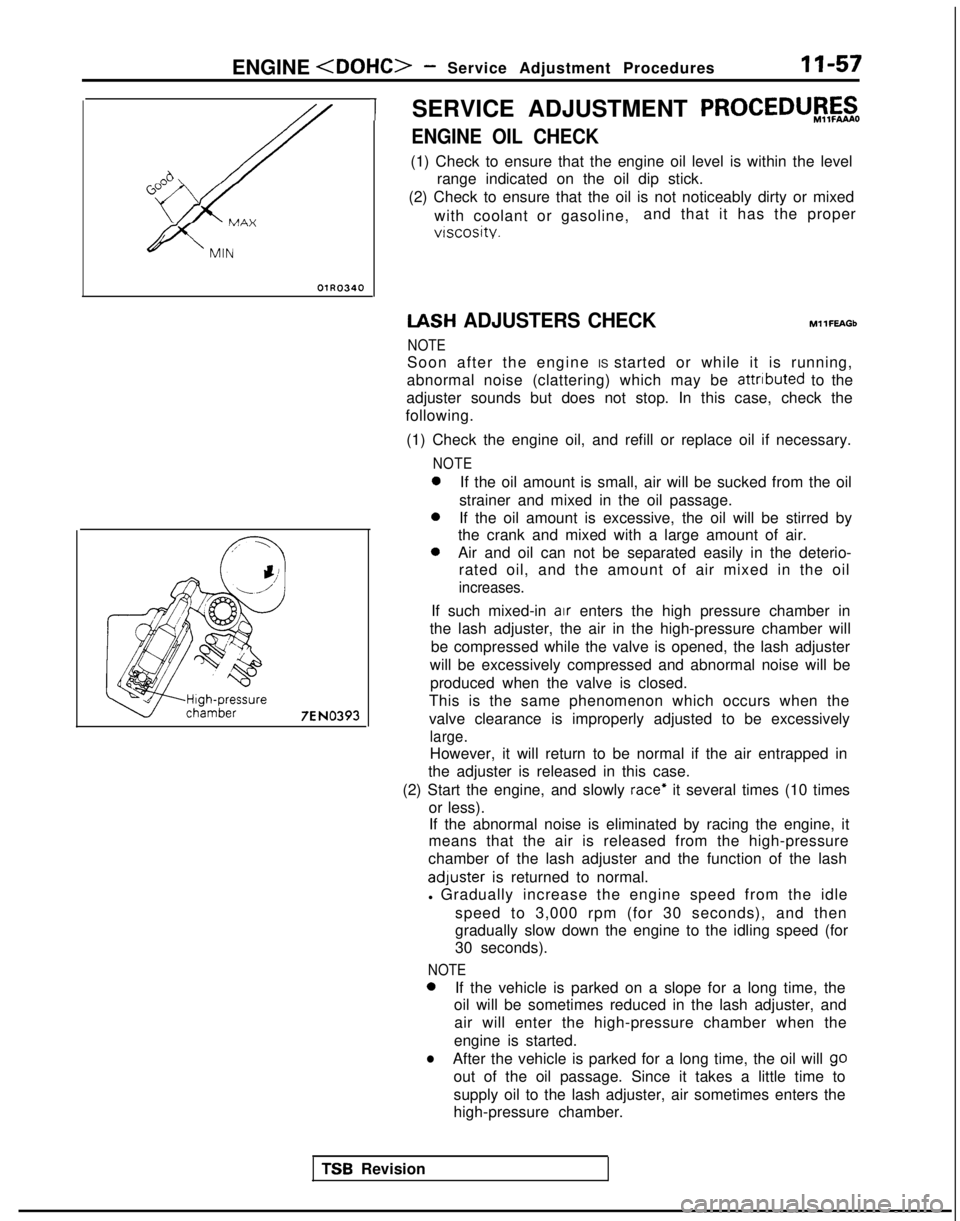
ENGINE OIL CHECK
(1) Check to ensure that the engine oil level is within the level
range indicated on the oil dip stick.
(2) Check to ensure that the oil is not noticeably dirty or mixed
with coolant or gasoline, and that it has the proper
vtscosity. IASH
ADJUSTERS CHECK
NOTE MllFEAGb
Soon after the engine IS started or while it is running,
abnormal noise (clattering) which may be attributed
to the
adjuster sounds but does not stop. In this case, check the
following.
(1) Check the engine oil, and refill or replace oil if necessary.
NOTE 0
If the oil amount is small, air will be sucked from the oil
strainer and mixed in the oil passage. 0
If the oil amount is excessive, the oil will be stirred by
the crank and mixed with a large amount of air. 0
Air and oil can not be separated easily in the deterio-
rated oil, and the amount of air mixed in the oil
increases.
If such mixed-in air enters the high pressure chamber in
the lash adjuster, the air in the high-pressure chamber will
be compressed while the valve is opened, the lash adjuster
will be excessively compressed and abnormal noise will be produced when the valve is closed.
This is the same phenomenon which occurs when the
valve clearance is improperly adjusted to be excessively
large.
However, it will return to be normal if the air entrapped in
the adjuster is released in this case.
(2) Start the engine, and slowly
race* it several times (10 times
or less). If the abnormal noise is eliminated by racing the engine, it
means that the air is released from the high-pressure
chamber of the lash adjuster and the function of the lash adluster
is returned to normal.
l Gradually increase the engine speed from the idle
speed to 3,000 rpm (for 30 seconds), and then
gradually slow down the engine to the idling speed (for
30 seconds).
NOTE 0
If the vehicle is parked on a slope for a long time, the
oil will be sometimes reduced in the lash adjuster, and
air will enter the high-pressure chamber when the
engine is started.
lAfter the vehicle is parked for a long time, the oil will go
out of the oil passage. Since it takes a little time to
supply oil to the lash adjuster, air sometimes enters the
high-pressure chamber.
TSR Revision
Page 108 of 1273
11-58ENGINE
4 Timing belt sideI
6EN0515
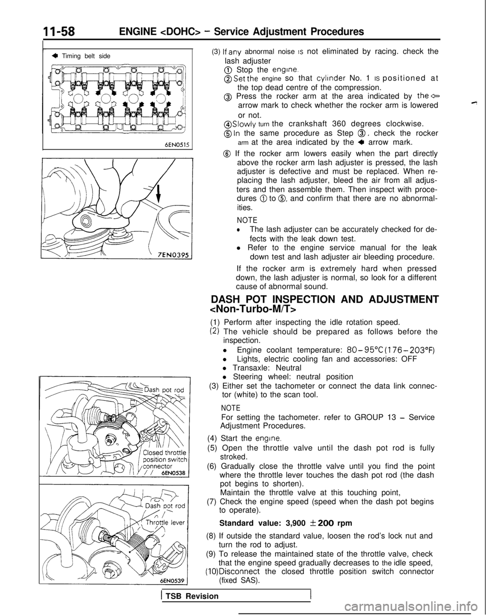
(3) lf
any abnormal noise IS not eliminated by racing. check the
lash adjuster
@ Stop the engine.
@ Set the engine so that cylinder
No. 1 IS positioned at
the top dead centre of the compression.
@ Press the rocker arm at the area indicated by the+
arrow mark to check whether the rocker arm is lowered
or not.
@ Slowly turn the crankshaft 360 degrees clockwise.
@ ln the same procedure as Step 0, check the rocker
arm at the area indicated by the
4 arrow mark.
@ If the rocker arm lowers easily when the part directly above the rocker arm lash adjuster is pressed, the lash
adjuster is defective and must be replaced. When re- placing the lash adjuster, bleed the air from all adjus-
ters and then assemble them. Then inspect with proce- dures
@I to 0, and confirm that there are no abnormal-
ities.
NOTE
lThe lash adjuster can be accurately checked for de-
fects with the leak down test.
l Refer to the engine service manual for the leak
down test and lash adjuster air bleeding procedure.
If the rocker arm is extremely hard when pressed
down, the lash adjuster is normal, so look for a different
cause of abnormal sound.
DASH POT INSPECTION AND ADJUSTMENT
(1) Perform after inspecting the idle rotation speed.
(2) The vehicle should be prepared as follows before the inspection.
l Engine coolant temperature:
80- 95°C
(176- 203°F)
lLights, electric cooling fan and accessories: OFF
l Transaxle: Neutral
l Steering wheel: neutral position
(3) Either set the tachometer or connect the data link connec- tor (white) to the scan tool.
NOTE
For setting the tachometer. refer to GROUP 13 - Service
Adjustment Procedures.
(4) Start the
engine.
(5) Open the throttle valve until the dash pot rod is fully
stroked.
(6) Gradually close the throttle valve until you find the point where the throttle lever touches the dash pot rod (the dashpot begins to shorten).
Maintain the throttle valve at this touching point,
(7) Check the engine speed (speed when the dash pot begins to operate).
Standard value: 3,900
f 200 rpm
(8) If outside the standard value, loosen the rod’s lock nut and turn the rod to adjust.
(9) To release the maintained state of the throttle valve, check that the engine speed gradually decreases to the idle speed, (10)Disconnect
the closed throttle position switch connector
(fixed SAS).
1 TSB Revision
Page 155 of 1273
FUEL SYSTEM
No.
43
4
-
Diagnostic trouble code
Output signal pattern On-board
diagnostic item Check item (Remedy)
Memory
EGRl Harness and connector
Retained
l EGR solenoid
L u u u I nnnl EGR valve control vacuum12A0105
Normal -state
-
H
L12A0104I 1
NOTEReplace the engine control module if a diagnostic trouble code is output\
although the inspection reveals that there is no
oroblem
with the check items.
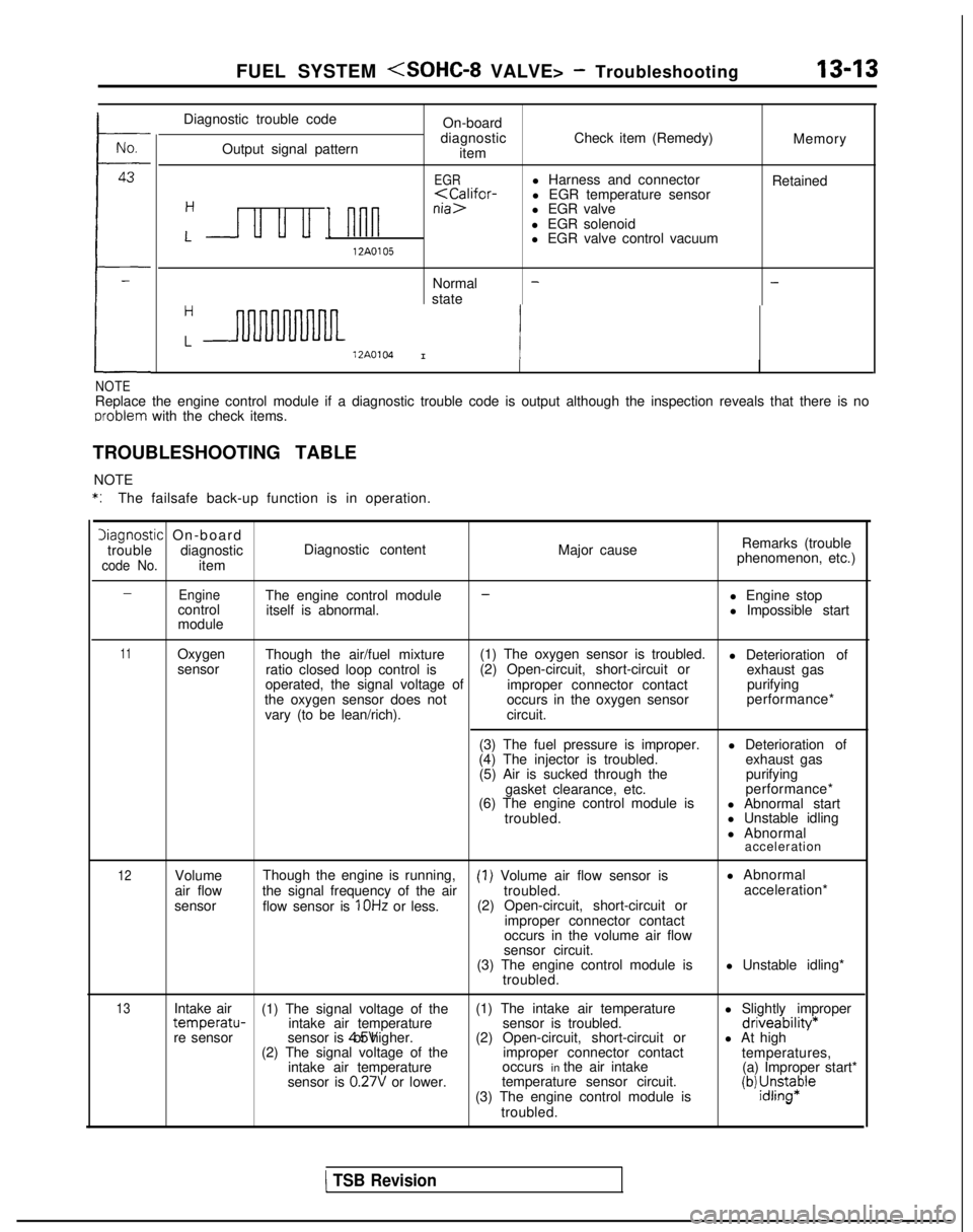
TROUBLESHOOTING TABLE NOTE
*:The failsafe back-up function is in operation.
Diagnostic On-board
trouble diagnostic Diagnostic content
code No.item Major cause
Remarks (trouble
phenomenon, etc.)
-EngineThe engine control module-l Engine stop
control itself is abnormal. l Impossible start
module
11Oxygen Though the air/fuel mixture (1) The oxygen sensor is troubled.
l Deterioration of
sensor ratio closed loop control is (2) Open-circuit, short-circuit or
exhaust gas
operated, the signal voltage of improper connector contactpurifying
the oxygen sensor does not occurs in the oxygen sensorperformance*
vary (to be lean/rich). circuit.
(3) The fuel pressure is improper. l Deterioration of
(4) The injector is troubled. exhaust gas
(5) Air is sucked through the purifying
gasket clearance, etc. performance*
(6) The engine control module is l Abnormal start
troubled. l Unstable idling
l Abnormal
acceleration
12Volume
air flow
sensor Though the engine is running,(I) Volume air flow sensor is
l Abnormal
the signal frequency of the air troubled.acceleration*
flow sensor is
1 OHz or less. (2) Open-circuit, short-circuit or
improper connector contact
occurs in the volume air flow
sensor circuit.
(3) The engine control module is l Unstable idling*
troubled.
13Intake air (1) The signal voltage of the (1) The intake air temperature
l Slightly impropertemperatu-intake air temperaturesensor is troubled.driveability*re sensorsensor is 4.5V or higher.
(2) Open-circuit, short-circuit or l At high
(2) The signal voltage of the improper connector contact
temperatures,
intake air temperature occurs in the air intake
(a) Improper start*
sensor is
0.27V or lower. temperature sensor circuit.
(3) The engine control module is(b) ;J;pe
troubled.
1 TSB Revision
Page 156 of 1273
13-14
FUEL SYSTEM
Iiagnostic On-boar
d
trouble diagnostic Diagnostic content Major causeRemarks (trouble
phenomenon, etc.)
code No. item
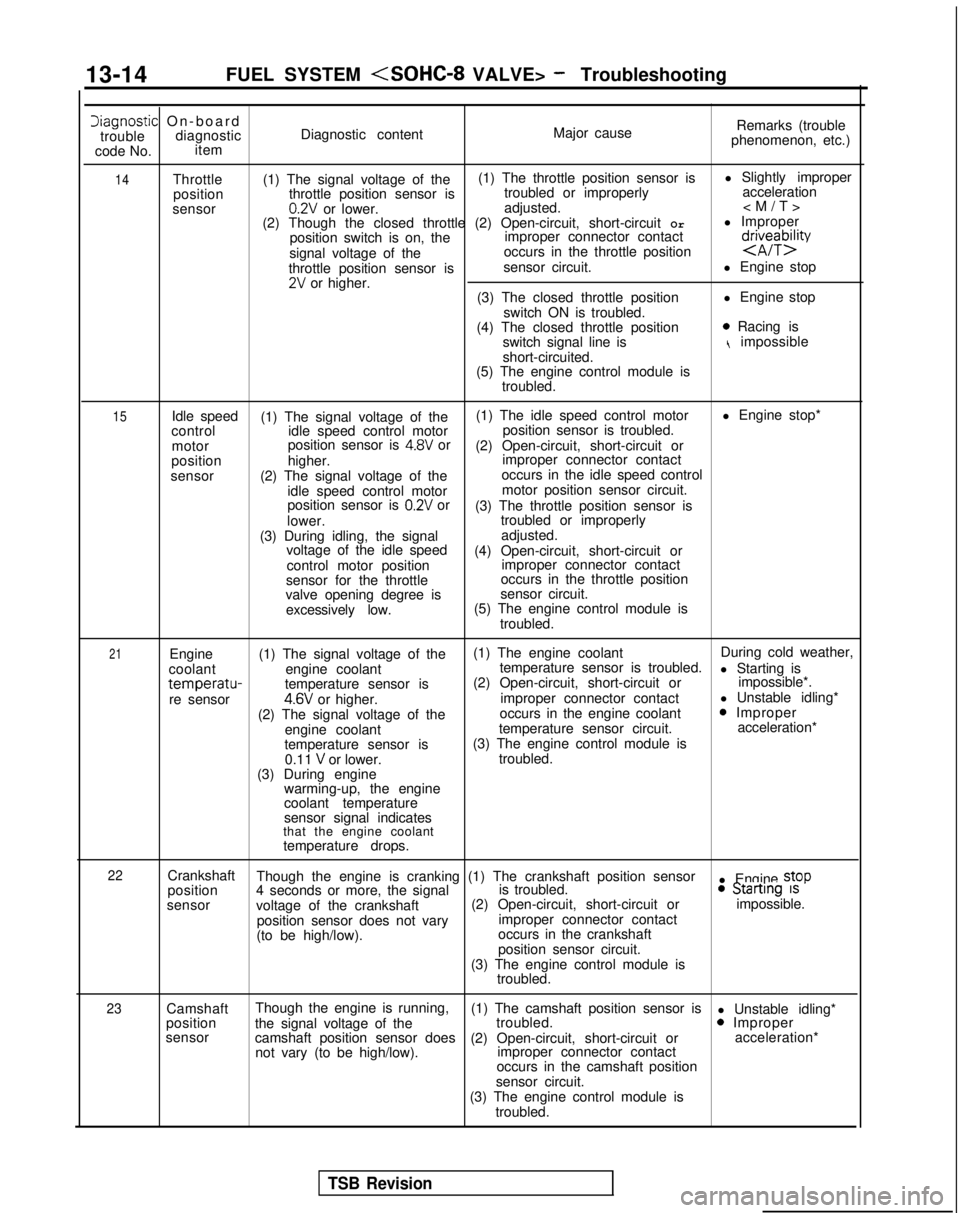
14Throttle
(1) The signal voltage of the (1) The throttle position sensor is
l Slightly improper
position throttle position sensor is troubled or improperly
acceleration
sensor
0.2V or lower. adjusted.
(2) Though the closed throttle (2) Open-circuit, short-circuit Orl Improper
position switch is on, the improper connector contact
signal voltage of the occurs in the throttle position
d$eybzty
throttle position sensor is
sensor circuit.
l Engine stop2V or higher.
(3) The closed throttle position l Engine stop
switch ON is troubled.
(4) The closed throttle position
0 Racing is
switch signal line ist impossible
short-circuited.
(5) The engine control module is
troubled.
15Idle speed (1) The signal voltage of the (1) The idle speed control motor
l Engine stop*
control idle speed control motor position sensor is troubled.
motor position sensor is
4.8V or
(2) Open-circuit, short-circuit or
position higher. improper connector contact
sensor (2) The signal voltage of the occurs in the idle speed control
idle speed control motor motor position sensor circuit.
position sensor is
0.2V or (3) The throttle position sensor is
lower. troubled or improperly
(3) During idling, the signal adjusted.
voltage of the idle speed (4) Open-circuit, short-circuit or
control motor position improper connector contact
sensor for the throttle occurs in the throttle position
valve opening degree is sensor circuit.
excessively low. (5) The engine control module is
troubled.
21Engine (1) The signal voltage of the (1) The engine coolant
During cold weather,
coolant engine coolant temperature sensor is troubled.
l Starting is
temperatu-temperature sensor is(2) Open-circuit, short-circuit or
impossible*.
re sensor4.6V or higher. improper connector contact
l Unstable idling*
(2) The signal voltage of the occurs in the engine coolant0 Improper
engine coolant temperature sensor circuit. acceleration*
temperature sensor is (3) The engine control module is
0.11
V or lower. troubled.
(3) During engine warming-up, the engine
coolant temperature
sensor signal indicates
that the engine coolant
temperature drops.
22Crankshaft Though the engine is cranking (1) The crankshaft position sensor
l Engine stop
position 4 seconds or more, the signal is troubled.0 Startrng 1s
sensor
voltage of the crankshaft (2) Open-circuit, short-circuit or
impossible.
position sensor does not vary improper connector contact
(to be high/low). occurs in the crankshaft
position sensor circuit.
(3) The engine control module is troubled.
23Camshaft Though the engine is running,
(1) The camshaft position sensor is
l Unstable idling*
position the signal voltage of the troubled.0 Improper
sensor camshaft position sensor does (2) Open-circuit, short-circuit or acceleration*
not vary (to be high/low). improper connector contact
occurs in the camshaft position
sensor circuit.
(3) The engine control module is troubled.
TSB Revision