1989 MITSUBISHI GALANT stop start
[x] Cancel search: stop startPage 244 of 1273
13-102 FUEL SYSTEM
- On-Vehicule Inspection of MFI Components
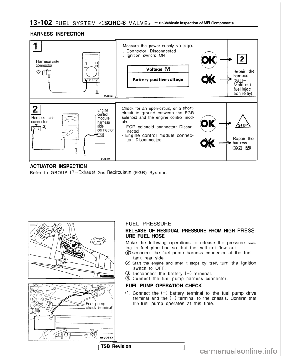
HARNESS INSPECTION
Harness sideconnector
L
Harness side
connector
Engine
1
control module
Check for an open-circuit, or a short-
circuit to ground between the EGR
solenoid and the engine control mod-
harnessule.side. EGR solenoid connector: Discon-connectornected+ Engine control module connec- tor: Disconnected Repair the
-+ harness.
Kzix2l-a)
-I
Measure the power supply voltage.
. Connector: Disconnected
. Ignition switch: ON
-
ACTUATOR INSPECTION
Refer to GROUP 17-Exhaust Gas Recirculatin (EGR) System
.
FUEL PRESSURE
RELEASE OF RESIDUAL PRESSURE FROM HIGH PRESS-
URE FUEL HOSE
Make the following operations to release the pressure remain-
ing in fuel pipe line so that fuel will not flow out. @ Disconnect the fuel pump harness connector at the fuel
tank rear side.
@ Start the engine and after it stops by itself, turn the ignitionswitch to OFF.
@ Disconnect the battery (-) terminal.
@I Connect the fuel pump harness connector.
FUEL PUMP OPERATION CHECK
(1) Connect the (+)
battery terminal to the fuel pump drive
terminal and the
(-) terminal to the chassis. Confirm that
the fuel pump operates at this time.
( TSB Revision1
Page 245 of 1273
FUEL SYSTEM
TSB Revision
---
I g$qfq, tcJ-s6FUO633
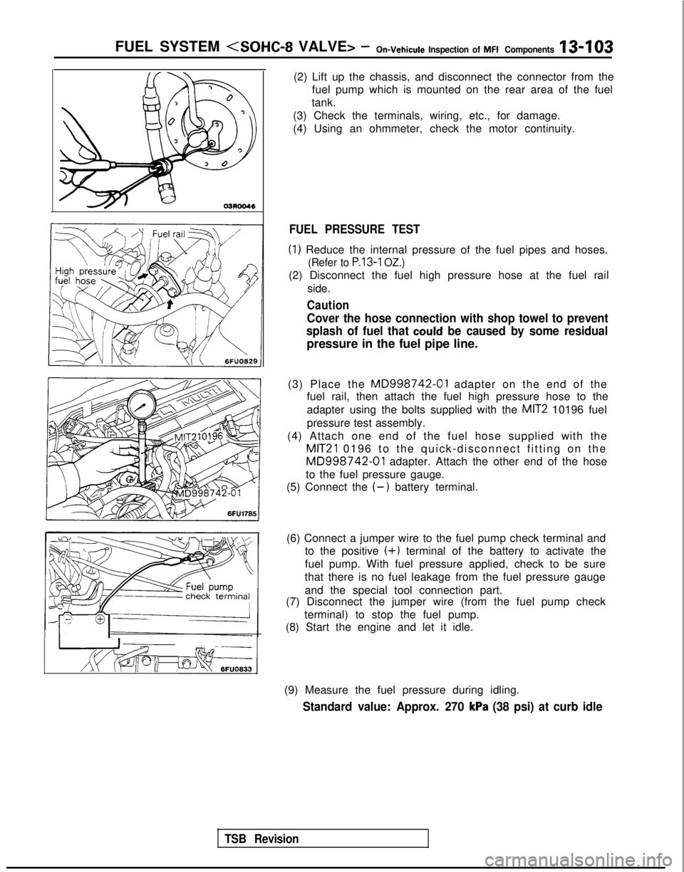
(2) Lift up the chassis, and disconnect the connector from the
fuel pump which is mounted on the rear area of the fuel
tank.
(3) Check the terminals, wiring, etc., for damage.
(4) Using an ohmmeter, check the motor continuity.
FUEL PRESSURE TEST
(1) Reduce the internal pressure of the fuel pipes and hoses.
(Refer to P.13-1 OZ.)
(2) Disconnect the fuel high pressure hose at the fuel rail
side.
Caution
Cover the hose connection with shop towel to prevent
splash of fuel that
could be caused by some residual
pressure in the fuel pipe line.
(3) Place the
MD998742-01 adapter on the end of the
fuel rail, then attach the fuel high pressure hose to the
adapter using the bolts supplied with the
MIT2 10196 fuel
pressure test assembly.
(4) Attach one end of the fuel hose supplied with the
MIT21 0196 to the quick-disconnect fitting on the
MD998742-01 adapter. Attach the other end of the hose
to the fuel pressure gauge.
(5) Connect the
(-) battery terminal.
(6) Connect a jumper wire to the fuel pump check terminal and to the positive
(+) terminal of the battery to activate the
fuel pump. With fuel pressure applied, check to be sure
that there is no fuel leakage from the fuel pressure gauge
and the special tool connection part.
(7) Disconnect the jumper wire (from the fuel pump check
terminal) to stop the fuel pump.
(8) Start the engine and let it idle.
(9) Measure the fuel pressure during idling.
Standard value: Approx. 270 kPa (38 psi) at curb idle
Page 265 of 1273
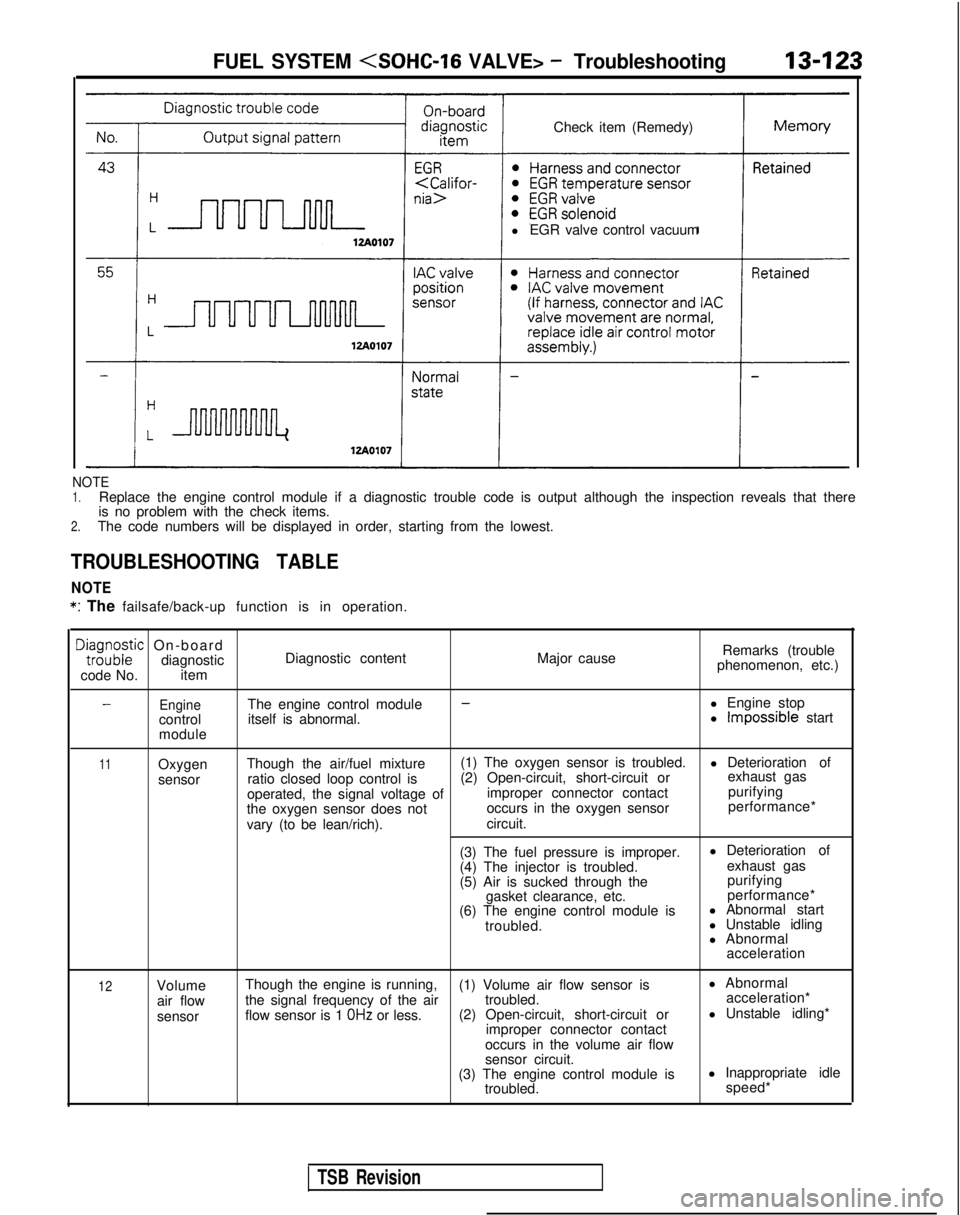
Check item (Remedy)
l EGR valve control vacuumFUEL SYSTEM
NOTE1.Replace the engine control module if a diagnostic trouble code is output\
although the inspection reveals that there
is no problem with the check items.
2.The code numbers will be displayed in order, starting from the lowest.
TROUBLESHOOTING TABLE
NOTE *:
The failsafe/back-up function is in operation.
DE;;;zic On-board
diagnostic
code No. item Diagnostic content
Major causeRemarks (trouble
phenomenon, etc.)
EngineThe engine control module--l Engine stop
control itself is abnormal. l Impossible start
module
11Oxygen
sensor Though the air/fuel mixture
(1) The oxygen sensor is troubled.
l Deterioration of
ratio closed loop control is (2) Open-circuit, short-circuit or exhaust gas
operated, the signal voltage of improper connector contact purifying
the oxygen sensor does not occurs in the oxygen sensor performance*
vary (to be lean/rich). circuit.
(3) The fuel pressure is improper. l Deterioration of
(4) The injector is troubled. exhaust gas
(5) Air is sucked through the purifying
gasket clearance, etc. performance*
(6) The engine control module is l Abnormal start
troubled. l Unstable idling
l Abnormal
acceleration
12Volume
air flow
sensor Though the engine is running,
(1) Volume air flow sensor is l Abnormal
the signal frequency of the air troubled. acceleration*
flow sensor is 1
OHz or less. (2) Open-circuit, short-circuit or l Unstable idling*
improper connector contact
occurs in the volume air flow
sensor circuit.
(3) The engine control module is l Inappropriate idle
troubled. speed*
TSB Revision
Page 266 of 1273
13-124FUEL SYSTEM
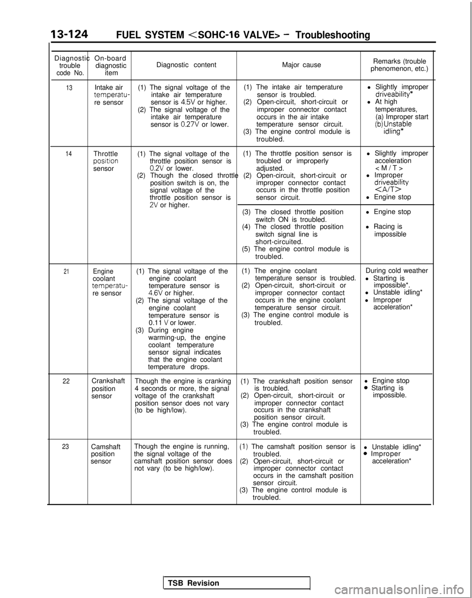
Diagnostic On-board
trouble diagnostic
code No.item Diagnostic content
Major causeRemarks (trouble
phenomenon, etc.)
13
14Intake air (1) The signal voltage of the (1) The intake air temperature
l Slightly impropertemperatu-intake air temperature
sensor is troubled.driveability*
re sensorsensor is 4.5V or higher.(2) Open-circuit, short-circuit or
l At high
(2) The signal voltage of the improper connector contacttemperatures,
intake air temperature occurs in the air intake (a) Improper start
sensor is
0.27V or lower. temperature sensor circuit.
(3) The engine control module isiWJ;sn$aple
troubled.
Throttle (1) The signal voltage of the (1) The throttle position sensor is
l Slightly improperposltion
throttle position sensor is troubled or improperly acceleration
sensor
0.2V or lower. adjusted.
(2) Though the closed throttle (2) Open-circuit, short-circuit or l Improper
position switch is on, the improper connector contact
signal voltage of the occurs in the throttle position
d&eTbQ
throttle position sensor is
sensor circuit. l Engine stop2V or higher.
(3) The closed throttle position l Engine stop
switch ON is troubled.
(4) The closed throttle position l Racing is
switch signal line is impossible
short-circuited.
(5) The engine control module is
troubled.
21Engine(1) The signal voltage of the (1) The engine coolant
During cold weather
coolant engine coolant temperature sensor is troubled.
l Starting is
temperatu-temperature sensor is(2) Open-circuit, short-circuit or
impossible*.
re sensor4.6V or higher. improper connector contact l Unstable idling*
(2) The signal voltage of the occurs in the engine coolant
l Improper
engine coolant temperature sensor circuit. acceleration*
temperature sensor is (3) The engine control module is
0.11
V or lower. troubled.
(3) During engine warming-up, the engine
coolant temperature
sensor signal indicates
that the engine coolant
temperature drops.
22Crankshaft Though the engine is cranking (1) The crankshaft position sensor l Engine stop
position 4 seconds or more, the signal is troubled.0 Starting is
sensor voltage of the crankshaft (2) Open-circuit, short-circuit or impossible.
position sensor does not vary improper connector contact
(to be high/low). occurs in the crankshaft
position sensor circuit.
(3) The engine control module is
troubled.
23Camshaft Though the engine is running,(1) The camshaft position sensor is
l Unstable idling*
position the signal voltage of the
troubled.0 Improper
sensor camshaft position sensor does
(2) Open-circuit, short-circuit or acceleration*
not vary (to be high/low). improper connector contact
occurs in the camshaft position
sensor circuit.
(3) The engine control module is
troubled.
TSB Revision
Page 267 of 1273
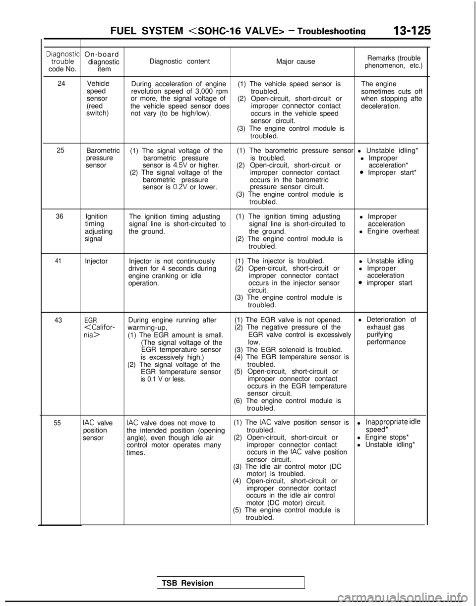
FUEL SYSTEM
Dta,i;o;ic On-board
diagnostic
code No. item Diagnostic content
Major causeRemarks (trouble
phenomenon, etc.)
24
Vehicle
speed
sensor
(reed
switch) During acceleration of engine
(1) The vehicle speed sensor is The engine
revolution speed of 3,000 rpm troubled.sometimes cuts off
or more, the signal voltage of (2) Open-circuit, short-circuit or when stopping afte
the vehicle speed sensor does improper connector
contact
deceleration.
not vary (to be high/low). occurs in the vehicle speed
sensor circuit.
(3) The engine control module is troubled.
25Barometric (1) The signal voltage of the (1) The barometric pressure sensor l Unstable idling*
pressure barometric pressure is troubled. l Improper
sensor sensor is
4.5V or higher.(2) Open-circuit, short-circuit or acceleration*
(2) The signal voltage of the improper connector contact0 Improper start*
barometric pressure occurs in the barometric
sensor is
0.2V or lower. pressure sensor circuit.
(3) The engine control module is troubled.
36Ignition
timing
adjusting
signal The ignition timing adjusting
(1) The ignition timing adjusting
l Improper
signal line is short-circuited to signal line is short-circuited toacceleration
the ground. the ground.l Engine overheat
(2) The engine control module is troubled.
41Injector Injector is not continuously
driven for 4 seconds during
engine cranking or idle
operation. (1) The injector is troubled.
(2) Open-circuit, short-circuit or improper connector contact
occurs in the injector sensor
circuit. l Unstable idling
l Improper acceleration
0 improper start
(3) The engine control module is troubled.
43EGRDuring engine running after (1) The EGR valve is not opened. l Deterioration of
purifying
(The signal voltage of the low. performance
EGR temperature sensor (3) The EGR solenoid is troubled.
is excessively high.) (4) The EGR temperature sensor is
(2) The signal voltage of the troubled.
EGR temperature sensor (5) Open-circuit, short-circuit or
is 0.1 V or less.improper connector contact
occurs in the EGR temperature
sensor circuit.
(6) The engine control module is
troubled.
55IAC valveIAC valve does not move to (1) The IAC valve position sensor is
position the intended position (opening troubled.l ;papp$Priate idle
sensor angle), even though idle air (2) Open-circuit, short-circuit or
l Engine stops*
control motor operates many improper connector contactl Unstable idling*
times. occurs in the
IAC valve position
sensor circuit.
(3) The idle air control motor (DC
motor) is troubled.
(4) Open-circuit, short-circuit or
improper connector contact
occurs in the idle air control
motor (DC motor) circuit.
(5) The engine control module is
troubled.
TSB Revision
Page 275 of 1273

FUEL SYSTEM
FUEL TANK AND FUEL LINEMIBEAAB
Symptom
Probable cause Remedy
Engine malfunctions
due to insufficient
fuel supply Bent or kinked fuel pipe or hose
Clogged fuel pipe or hose
Clogged fuel filter or in-tank fuel filter
Water in fuel filter Repair or replace
Clean or replace
Replace
Replace the fuel filter or clean the
fuel tank and fuel line
Dirty or rusted fuel tank interior
Clean or replace
Malfunctioning fuel pump
(Clogged filter in the pump)Replace
Evaporative emission
control system
malfunctions
[When fuel tank filler
tube cap is removed,
pressure releasingnoise is heard) Mispiping of vapor line
Disconnected vapor line piping joint
Folded, bent, cracked or clogged vapor line
Faulty fuel tank filler tube cap
Malfunctioning fuel tank pressure control valve Correct
Correct
Replace
Replace
Replace
SERVICE ADJUSTMENT
PROCEDURES
CURB IDLE SPEED INSPECTIONhll3MAE
(1) The vehicle should be prepared as follows before th
e
inspection.
lEngine coolant temperature: 85-95°C (185-203°F)
l Lights, electric cooling fan and accessories: OFF
l Transaxle: Neutral (P for vehicles with an automatic
transaxle)
(2) Connect a tachometer.
NOTE
Refer to
P.13-134 for information concerning connection Of
a tachometer.
(3) Set a timing light in position.
(4) Ground the terminal for adjustment of ignition timing.
(5) Start the engine and let it idle.
(6) Check whether or not the ignition timing is the standard
value; if not, adjust.
Standard value:
5”BTDC f 2”
(7) Stop grounding the terminal for adjustment of ignition timing.
(8) Let the engine idle for two minutes.
(9) Check the idling rpm.
Curb idle speed: 700
31100 rpm
NOTE
The idling rpm is automatically regulated by the idle aircontrol system.
(lO)lf not within the standard value range, refer to the CHECK
CHART CLASSIFIED BY PROBLEM SYMPTOMS and check
the
MFI component,
TS6 Revision1
Page 278 of 1273
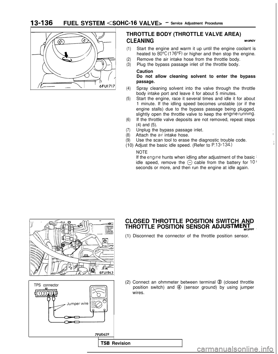
13-136FUEL SYSTEM
TPS connector
7FUO629
THROTTLE BODY (THROTTLE VALVE AREA)
CLEANINGMl3Rcv
(1)Start the engine and warm it up until the engine coolant is
heated to
80°C (176°F) or higher and then stop the engine.
(2)Remove the air intake hose from the throttle body.
(3)Plug the bypass passage inlet of the throttle body.
Caution
Do not allow cleaning solvent to enter the bypass
passage.
(4)Spray cleaning solvent into the valve through the throttle
body intake port and leave it for about 5 minutes.
(5)Start the engine, race it several times and idle it for about 1 minute. If the idling speed becomes unstable (or if the
engine stalls) due to the bypass passage being plugged,
slightly open the throttle valve to keep the engine
running.
(6)If the throttle valve deposits are not removed, repeat steps
(4) and (5).
(7)Unplug the bypass passage inlet.
(8)Attach the air intake hose.
(9)Use the scan tool to erase the diagnostic trouble code.
(10) Adjust the basic idle speed. (Refer to
P.13-134.)
NOTE
If the engrne hunts when idling after adjustment of the basic
idle speed, remove the
@ cable from the battery for 10
seconds or more, and then run the engine at idle again.
CLOSED THROTTLE POSITION SWITCH AND
THROTTLE POSITION SENSOR ADJUSTMEy,zIFF
(1) Disconnect the connector of the throttle position sensor.
(2) Connect an ohmmeter between terminal
@I (closed throttle
position switch) and
@ (sensor ground) by using jumper
wires.
TSB Revision
Page 350 of 1273
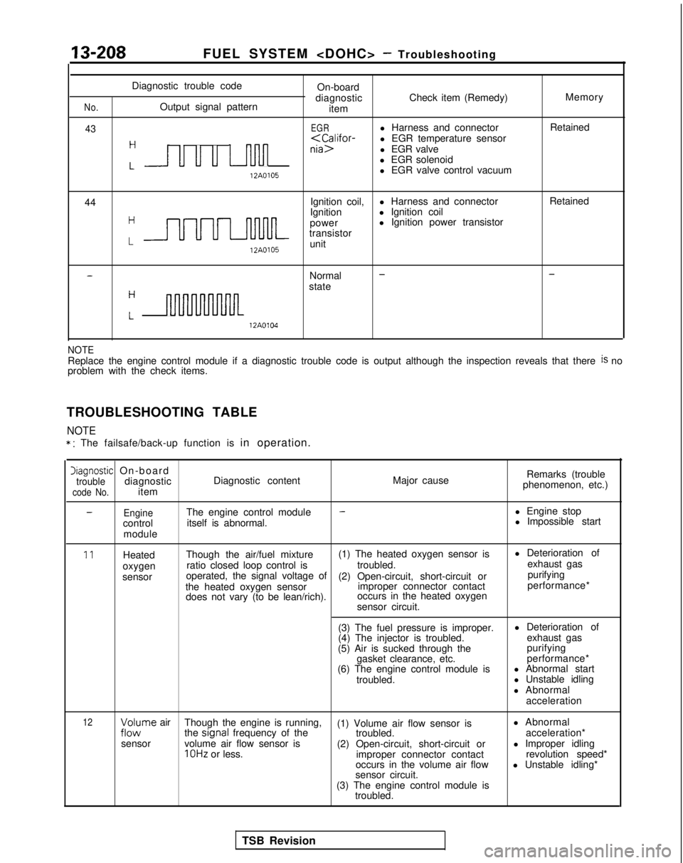
13-208FUEL SYSTEM
No.
43
Diagnostic trouble codeOn-board
diagnostic Check item (Remedy) Memory
Output signal pattern item
EGRl Harness and connector Retained
H
nia>l EGR valve
l EGR solenoid
L 12A0105
l EGR valve control vacuum
44 Ignition coil,
l Harness and connector Retained
Hl Ignition coil
LUUULnl-lM-
Ignition
power l Ignition power transistor
transistor 12A0105
unit
-Normal --
stateH
Lnm 12A0104
NOTEReplace the engine control module if a diagnostic trouble code is output\
although the inspection reveals that there is no
problem with the check items.
TROUBLESHOOTING TABLE
NOTE
* : The failsafe/back-up function is in operation.
Diagnostic On-boardtroublediagnosticcode No.itemDiagnostic content
Major causeRemarks (trouble
phenomenon, etc.)
-EngineThe engine control module-l Engine stop
control itself is abnormal. l Impossible start
module
11Heated Though the air/fuel mixture (1) The heated oxygen sensor is l Deterioration of
oxygen ratio closed loop control is
troubled.exhaust gas
sensor operated, the signal voltage of
(2) Open-circuit, short-circuit or purifying
the heated oxygen sensor improper connector contactperformance*
does not vary (to be lean/rich). occurs in the heated oxygen
sensor circuit.
(3) The fuel pressure is improper. l Deterioration of
(4) The injector is troubled. exhaust gas
(5) Air is sucked through the purifying
gasket clearance, etc. performance*
(6) The engine control module is l Abnormal start
troubled. l Unstable idling
l Abnormal acceleration
12;zc$rne air Though the engine is running,
(1) Volume air flow sensor is l Abnormal
the signal
frequency of the
troubled. acceleration*
sensor volume air flow sensor is
(2) Open-circuit, short-circuit or l Improper idling
1 OHz or less.
improper connector contact revolution speed*
occurs in the volume air flow l Unstable idling*
sensor circuit.
(3) The engine control module is troubled.
TSB Revision