1989 MITSUBISHI GALANT stop start
[x] Cancel search: stop startPage 507 of 1273
AUTO-CRUISE CONTROL SYSTEM - Troubleshooting13-365
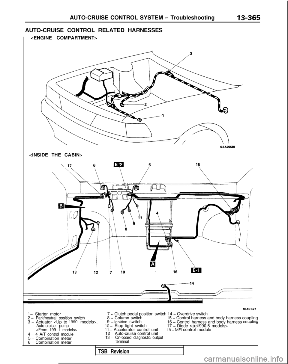
AUTO-CRUISE CONTROL RELATED HARNESSES
16AO621
1 - Starter motor 7 - Clutch pedal position switch 14 - Overdrive switch2 - Park/neutral position switch8 - Column switch
15 - Control harness and body harness coupling
3 - Actuator
16 - Control harness and body harness CouplingAuto-cruise pump10 - Stop light switch 17 - Diode
5
- Combination meter13 - On-board diagnostic output
6 - Combination meterterminal
TSB Revision
Page 540 of 1273
13-398
AUTO-CRUISE CONTROL SYSTEM - Setice Adjustment procedures
03*02.5*
1
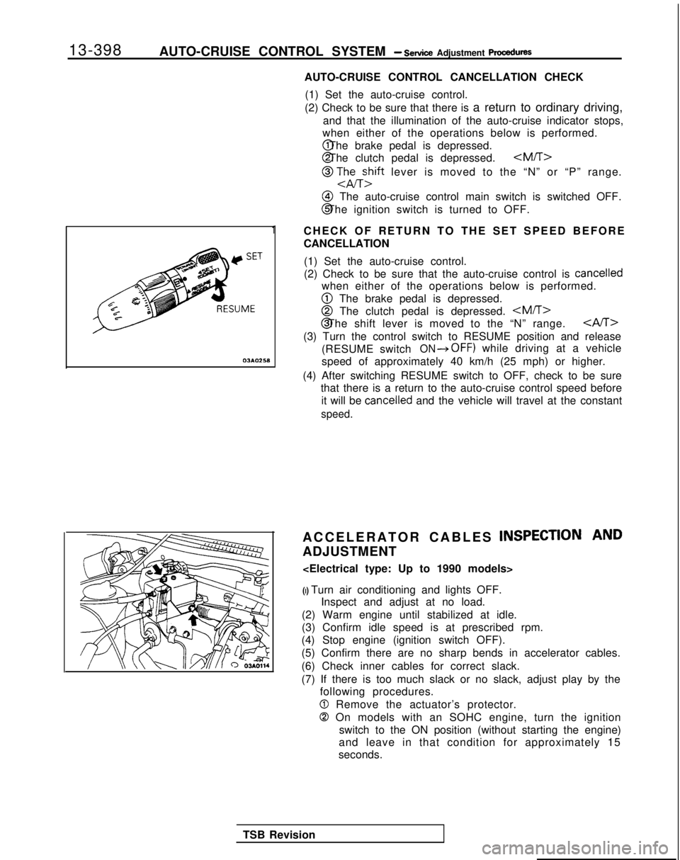
AUTO-CRUISE CONTROL CANCELLATION CHECK
(1) Set the auto-cruise control.
(2) Check to be sure that there is a return to ordinary driving,
and that the illumination of the auto-cruise indicator stops,
when either of the operations below is performed. @ The brake pedal is depressed.
@ The clutch pedal is depressed.
@ TJhEzift lever is moved to the “N” or “P” range.
@I The auto-cruise control main switch is switched OFF.
@ The ignition switch is turned to OFF.
CHECK OF RETURN TO THE SET SPEED BEFORE
CANCELLATION (1) Set the auto-cruise control.
(2) Check to be sure that the auto-cruise control is
cancelled
when either of the operations below is performed.
@ The brake pedal is depressed.
@ The clutch pedal is depressed.
CAST>
(3) Turn the control switch to RESUME position and release
(RESUME switch
ON*OFF) while driving at a vehicle
speed of approximately 40 km/h (25 mph) or higher.
(4) After switching RESUME switch to OFF, check to be sure that there is a return to the auto-cruise control speed before
it will be
cancelled and the vehicle will travel at the constant
speed.
ACCELERATOR CABLES INSPECTION AND
ADJUSTMENT
(I) Turn air conditioning and lights OFF. Inspect and adjust at no load.
(2) Warm engine until stabilized at idle.
(3) Confirm idle speed is at prescribed rpm.
(4) Stop engine (ignition switch OFF).
(5) Confirm there are no sharp bends in accelerator cables.
(6) Check inner cables for correct slack.
(7) If there is too much slack or no slack, adjust play by the following procedures.
0 Remove the actuator’s protector.
0 On models with an SOHC engine, turn the ignition
switch to the ON position (without starting the engine)
and leave in that condition for approximately 15
seconds.
TSB Revision
Page 542 of 1273
13-400AUTO-CRUISE CONTROL SYSTEM - Service Adjustment procedures
rThrottle cableAdjusting nut B
\uto-cruise dontrolcable
ThrottlecableAdjusting nut D
A
03A0281
Stopper
ThrottleLock nut/ Adjusting nut B
Stopper07AOO54
07AOO55
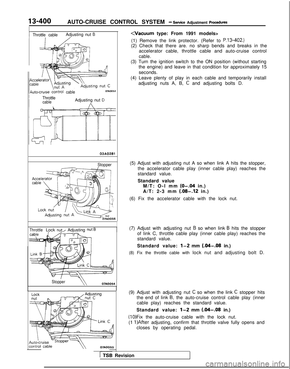
(1) Remove the link protector. (Refer to
P.13-402.)
(2) Check that there are. no sharp bends and breaks in the accelerator cable, throttle cable and auto-cruise control
cable.
(3) Turn the ignition switch to the ON position (without startingthe engine) and leave in that condition for approximately 15
seconds.
(4) Leave plenty of play in each cable and temporarily install adjusting nuts A, B,
C and adjusting bolts D.
(5) Adjust with adjusting nut A so when link A hits the stopper, the accelerator cable play (inner cable play) reaches the
standard value.
Standard valueM/T: O-l mm
(O-.04 in.)
A/T: 2-3 mm
(.08-.12 in.)
(6) Fix the accelerator cable with the lock nut.
(7) Adjust with adjusting nut
B so when link B hits the stopper
of link C, throttle cable play (inner cable play) reaches the
standard value.
Standard value:
l-2 mm (&I-.08 in.)
(8) Fix the throttle cable with lock nut and adjusting bolt D.
(9) Adjust with adjusting nut
C so when the link C stopper hits
the end of link
B, the auto-cruise control cable play (inner
cable play) reaches the standard value.
Standard value:
l-2 mm (.04-.08 in.)
(1O)Fix the auto-cruise cable with the lock nut.
(1
l)After adjusting, confirm that throttle valve fully opens and
closes by operating pedal.
-
rTSB Revision
Page 732 of 1273
23-26AUTOMATIC TRANSAXLE - Troubleshooting
HOT
TFA0715
AW
D
TFA0700
DATA LINK AND TEST
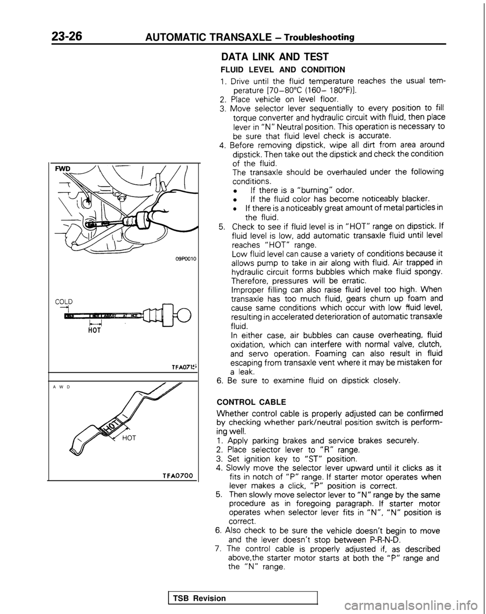
FLUID LEVEL AND CONDITION
1. Drive until the
fluid
temperature
reaches the
usual tem-
perature
[70-80°C (160- 18O”F)l.
2. Place
vehicle
on level floor.
3. Move
selector
lever sequentially
to
every
position
to fill
torque
converter
and hydraulic circuit
with fluid,
then
place
lever in “N” Neutral position.
This operation is necessary
t0
be sure that fluid
level check is accurate.
4. Before
removing
dipstick,
wipe all dirt from area around
dipstick.
Then take out
the
dipstick
and check the
condition
of the
fluid.
The
transaxle
should be overhauled under the following
conditions.
l If there
is a “burning” odor.
l If the
fluid
color
has become
noticeably
blacker.
lIf there
is a noticeably
great
amount
of metal particles in
the
fluid.
5.Check to
see if fluid
level is in “HOT” range on dipstick.
If
fluid
level is low, add automatic
transaxle
fluid
until level
reaches “HOT” range.
Low
fluid
level can cause a variety of
conditions
because it
allows
pump
to
take
in air along with fluid. Air trapped in
hydraulic circuit
forms
bubbles
which
make fluid
spongy.
Therefore,
pressures
will be erratic. Improper filling
can also raise fluid level too
high. When
transaxle
has too
much fluid,
gears churn up foam and
cause same
conditions
which occur with low fluid
level, resulting
in accelerated deterioration
of
automatic
transaxle
fluid.
In
either
case, air bubbles
can cause overheating,
fluid
oxidation,
which can interfere
with normal valve, clutch,
and
servo
operation.
Foaming can also result
in fluid
escaping
from
transaxle
vent where it
may be mistaken
for
a leak.
6. Be
sure to
examine
fluid
on dipstick
closely.
CONTROL CABLE
Whether control
cable is properly
adjusted
can be confirmed
by
checking
whether park/neutral
position
switch is perform-
ing
well.
1.
Apply
parking brakes and service
brakes securely.
2. Place
selector
lever
to
“R” range.
3. Set ignition
key to
“ST” position.
4.
Slowly
move
the
selector
lever
upward
until it
clicks as it
fits in
notch of “P” range. If starter
motor
operates
when
lever makes a click, “P”
position
is correct.
5.Then slowly
move
selector
lever to “N” range by
the
same
procedure as in foregoing
paragraph. If starter
motor
operates
when selector
lever
fits in ‘IN”, “N” position
is correct.
6.
Also check to be sure the
vehicle
doesn’t
begin to move
and
the
lever
doesn’t
stop
between
P-R-N-D.
7. The control
cable is properly
adjusted if, as described
above,the
starter
motor
starts
at both the
“P” range and the
“N” range.
TSB Revision
Page 740 of 1273
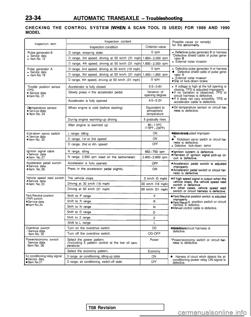
23-34AUTOMATIC TRANSAXLE - Troubleshooting
CHECKING THE CONTROL SYSTEM (WHEN
A SCAN TOOL IS USED) FOR 1989 AND 1990
MODEL
Pulse generator Al Service datal Item No. 1’9
Throttle positron sensorTPS)m Service dataD Item No. 21
I!(
(44
c44
I!.,
I(,
\,4
:44 C
.
.
F.
.
A00
D range, stopprng state 0 rpml Defectrve pulse generator B or harness
D range, 3rd speed, driving at 50 km/h (31 mph) 1.600-2.000
rpm*Defective shield cable of pulse gene-
rator B
D range, 4th speed, drivrng at 50 km/h (31 mph) 1.600-2.000
rpml External noise invasion
D range. 2nd speed, driving at 30 km/h (19 mph) 0 rpml Defective pulse generator A or harness
D range, 3rd speed, driving at 50 km/h (31 mph) 1.400-1.800
rpml Defective shield cable of pulse gene-rator A
D range, 4th speed, drivrng at 50 km/h (31 mph) 0 rpml External noise Invasion *Slip
of kick-down brake
Accelerator is fully closed. 0.5-0.6V
l If voltage is high at the full opening or
Slowly press In the accelerator pedal.Variatron of
closing, TPS is adjusted improperly.
opening degreeelf no variation is observed, TPS or
circuit harness is defective.
Accelerator is fully opened.
4.5-5.ovelf it does not vary smoothly, TPS or
accelerator cable is defective. Xl temperature sensor
) Servtce data) Item No. 24
When engtne is cold (before starting)
Equivalent toatmospheric
temperature *Oil
temperature sensor or circuit har-ness is defective.
cickdown servo switch) Servrce data1 Item No. 25
Durrng engine warming-up driving
After engine is warmed up
L range. idling
D range, 1st or 3rd speed
D range, 2nd or 4th speed
It gradually rises.
80- 110°C(176”F-230°F)
ON *Kick-down servo IS adjusted improper-
ONIV.l Kickdown servo switch or circuit har-
OFFness is defective.l Defectivekick-down
servo
bItem No.34 alposition switch or circuitharness is defective.*Manual
control cable is defective.
Iverdnve switch1 Servrce data1 item No. 35
‘owedeconomy swatch‘Servrce data
Item No. 36 Shift to
L range
Turn on the overdrive switch.
Turn off the overdrive switch.
Select the power pattern. (Including
E pattern control at the low oil tem-perature)
L
OD
OD-OFF
Power moverdrive switch or circuit harness is
defective.
*Power/economy switch or circuit har-ness is defective.
Select the economy pattern.
Economy
.ir conditioning relay signalService dataD range. air conditioning, idling-up stateONl Harness of circuit which detects the air
Item No.37D range, air conditioning, switch-off stateOFFconditioning power relay ON signal isdefective.
Inspectron ttemInspectron content
Inspection conditionPossible cause (or remedy)
Criterion value for the abnormalrty
Pulse generator Bl Service datal Item No. 13
TSB Revision
Page 743 of 1273
AUTOMATIC TRANSAXLE - Troubleshooting23-37
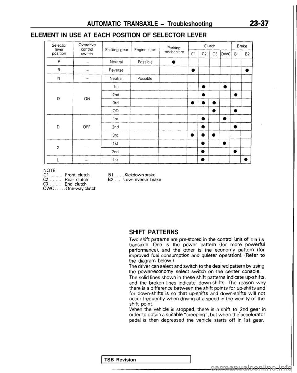
ELEMENT IN USE AT EACH POSITION OF SELECTOR LEVER
NOTECl. . . . . . . . .FrontclutchC2 . . . . . . . . .Rear clutchC3 . . . . . . . . .EndclutchOWC . . . . . . One-way clutchBl
. . . . . . Kickdown brake82 .._.. Low-reverse brake
SHIFT PATTERNS
Two
shift patterns
are pm-stored
in the
control
‘unit of
this transaxle.
One is the
power
pattern
(for more powerful
performance), and
the
other
is the
economy
pattern
(for
improved
fuel consumption
and quieter
operation).
(Refer to
the
diagram below.)
The
driver
can select
and switch to the
desired
pattern
by
using
the
power/economy
select
switch on the
center
console.
The solid lines
shown
in these
shift patterns
indicate
up-shifts,
and
the
broken lines indicate. down-shifts. The reason why there
is a difference
between
the
shift points for
up-shifts
and for
down-shifts is so that up-shifts
and down-shifts will not
occur frequently
when
driving
at
a speed in the
vicinity of the
shift
point.
When the
vehicle
is stopped,
there
is a shift to -2nd gear
in order
to
obtain
a suitable
“creeping”, but
when the accelerator
pedal is
then
depressed
the
vehicle
starts
off in 1st gear.
TSB Revision
Page 789 of 1273
AUTOMATIC TRANSAXLE - Service Adjustment Procedures23-83
I:
I’
4989 models>
09A0140
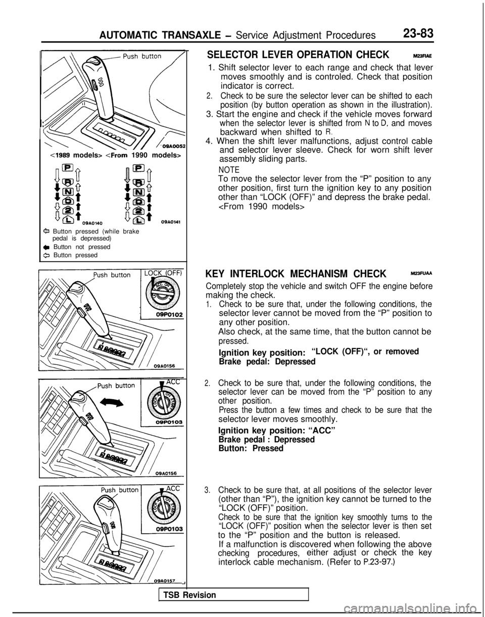
6% Button pressed (while brakepedal is depressed)
c Button not pressed
0 Button pressed
SELECTOR LEVER OPERATION CHECKM23flAE
1. Shift selector lever to each range and check that lever
moves smoothly and is controled. Check that position
indicator is correct.
2.Check to be sure the selector lever can be shifted to each
position (by button operation as shown in the illustration).
3. Start the engine and check if the vehicle moves forward
when the selector lever is shifted from N to D, and moves
backward when shifted to R.
4. When the shift lever malfunctions, adjust control cable and selector lever sleeve. Check for worn shift lever
assembly sliding parts.
NOTE
To move the selector lever from the “P” position to any
other position, first turn the ignition key to any position
other than “LOCK (OFF)” and depress the brake pedal.
KEY INTERLOCK MECHANISM CHECKM23FUAA
Completely stop the vehicle and switch OFF the engine before
making the check.
1.Check to be sure that, under the following conditions, the
selector lever cannot be moved from the “P” position to
any other position.
Also check, at the same time, that the button cannot be
pressed.
Ignition key position:“LOCK (OFF)“, or removed
Brake pedal: Depressed
2.Check to be sure that, under the following conditions, the selector lever can be moved from the “P” position to any
other position.
Press the button a few times and check to be sure that the
selector lever moves smoothly.
Ignition key position: “ACC”
Brake pedal : Depressed
Button: Pressed
3.Check to be sure that, at all positions of the selector lever
(other than “P”), the ignition key cannot be turned to the
“LOCK (OFF)” position.
Check to be sure that the ignition key smoothly turns to the
“LOCK (OFF)” position when the selector lever is then set
to the “P” position and the button is released.
If a malfunction is discovered when following the above
checking procedures,either adjust or check the key
interlock cable mechanism. (Refer to
P.23-97.)
-I
TSB Revision
Page 942 of 1273
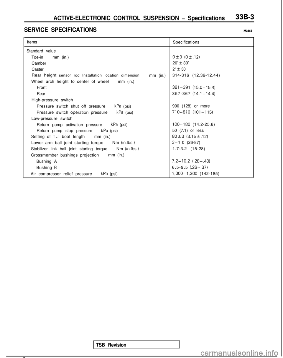
ACTIVE-ELECTRONIC CONTROL SUSPENSION - Specifications33B-3
SERVICE SPECIFICATIONSM33cE-
ItemsSpecifications
Standard value Toe-in mm (in.)
O&3 (O-t.12)
Camber 20’ t 30’
Caster
2” t 30’
Rear height sensor rod Installation location dimension
mm (in.)314-316 (12.36-12.44)
Wheel arch height to center of wheel mm (in.)
Front
381-391 (15.0-15.4)
Rear357-367 (14.1-14.4)
High-pressure switch
Pressure switch shut off pressure
kPa (psi) 900 (128) or more
Pressure switch operatton
pressure
kPa (psi)710-810 (101-115)
Low-pressure switch
Return pump activation pressure
kPa (psi)100-180 (14.2-25.6)
Return pump stop pressure
kPa (psi) 50 (7.1) or less
Setting of
T.J. boot length mm (in.)80+3 (3.152.12)
Lower arm ball joint starting torque Nm (inlbs.)3-l 0 (26-87)
Stabilizer link ball joint starting torque Nm (in.lbs.)
1.7-3.2 (15-28)
Crossmember bushings projection mm (in.)
Bushing A
7.2-10.2 (.28-.40)
Bushing B6.5-9.5 (.26-.37)
Air compressor relief pressurekPa (psi) l,OOO-1,300
(142-185)
TSB Revision