1989 MITSUBISHI GALANT fuse chart
[x] Cancel search: fuse chartPage 481 of 1273
AUTO-CRUISE CONTROL SYSTEM - Troubleshooting13-339
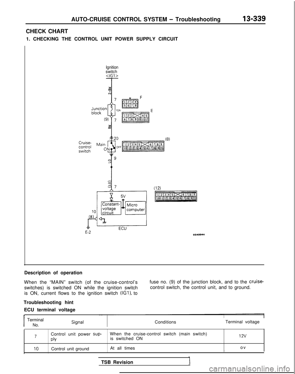
CHECK CHART
1. CHECKING THE CONTROL UNIT POWER SUPPLY CIRCUIT
Ignition
switch
(8)
Description of operation
When the “MAIN” switch (of the cruise-control’s switches) is switched ON while the ignition switch
is ON, current flows to the ignition switch (IGl),
to fuse no. (9) of the junction block, and to the cruise-
control switch, the control unit, and to ground.
Troubleshooting hint ECU terminal voltage
t
Terminal voltageI
Terminal
No.Conditions
7Control unit power sup-
When the cruise-control switch (main switch)
is switched ON 12v
PlY
10Control unit ground
At all times o
v
t
TSB Revision
Page 496 of 1273
13-354AUTO-CRUISE CONTROL SYSTEM - Troubleshooting
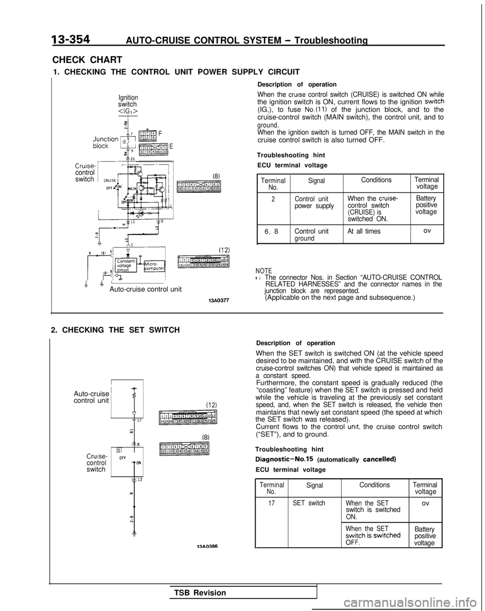
CHECK CHART 1. CHECKING THE CONTROL UNIT POWER SUPPLY CIRCUIT
Ignitionswitch
Cruise-control
switchI(8)
pmTzREq
4 atAuto-cruise control unit
13A0377
Description of operation
When the cruise control switch (CRUISE) is switched ON whilethe ignition switch is ON, current flows to the ignition swrtch(IG,), to fuse No.(ll) of the junction block, and to the
cruise-control switch (MAIN switch), the control unit, and to
ground.When the ignition switch is turned OFF, the MAIN switch in thecruise control switch is also turned OFF.
Troubleshooting hint ECU terminal voltage
Terminal SignalConditions TerminalNo.voltage
2Control unitWhen the cruise-Battery
power supply control switch positive
(CRUISE) isvoltage
switched ON.
6. 8Control unitgroundAt all timesov
NOTEl :The connector Nos. in Section “AUTO-CRUISE CONTROL RELATED HARNESSES” and the connector names in the
junction block are represented.
(Applicable on the next page and subsequence.)
2. CHECKING THE SET SWITCH
I
Auto-cruise ’control unitT
v“17 3
A-3SETCrulse-OFFcontrolTONswitch
>: 13
63)
13AO386Description of operation
When the SET switch is switched ON (at the vehicle speed desired to be maintained, and with the CRUISE switch of the
cruise-control switches ON) that vehicle speed is maintained as
a constant speed.
Furthermore, the constant speed is gradually reduced (the “coasting” feature) when the SET switch is pressed and held
while the vehicle is traveling at the previously set constant
speed, and, when the SET switch is released, the vehicle thenmaintains that newly set constant speed (the speed at which
the SET switch was released).
Current flows to the control
unit. the cruise control switch
(“SET”), and to ground.
Troubleshooting hint
Diagnostic-No.15 (automatically cancelled)
ECU terminal voltage
Terminal SignalConditions TerminalNo.voltage
17SET switch
When the SETovswitch is switchedON.
When the SET
;yv$h is swrtched Battery
positive
voltage
TSB Revision
Page 950 of 1273
ACTIVE-ELECTRONIC CONTROL SUSPENSION - Troubleshooting 33B-11
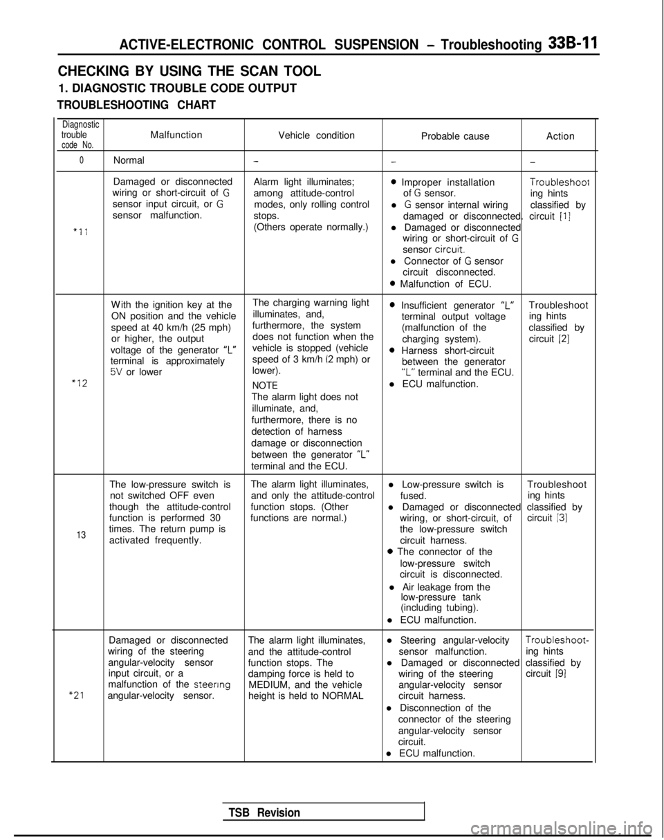
CHECKING BY USING THE SCAN TOOL
1. DIAGNOSTIC TROUBLE CODE OUTPUT
TROUBLESHOOTING CHART
DiagnostictroubleMalfunctionVehicle conditioncode No.Probable causeAction
0Normal---
Damaged or disconnected
Alarm light illuminates;0 Improper installation Troubleshoof
wiring or short-circuit of Gamong attitude-control of G sensor.
sensor input circuit, or Ging hints
modes, only rolling control
sensor malfunction. l
G sensor internal wiring
classified by
stops. damaged or disconnected. circuit
[I]
“11(Others operate normally.)l Damaged or disconnected
wiring or short-circuit of
G
sensor circurt.
l Connector of
G sensor
circuit disconnected.
0 Malfunction of ECU.
W
ith the ignition key at the
The charging warning light
ON position and the vehicle illuminates, and,
0 Insufficient generator “L”Troubleshoot
speed at 40 km/h (25 mph) furthermore, the system terminal output voltage
ing hints
or higher, the output does not function when the (malfunction of the
classified by
charging system). circuit
[2]
voltage of the generator ‘I”vehicle is stopped (vehicle0 Harness short-circuit
terminal is approximately speed of 3 km/h (2 mph) or
5V or lower
lower). between the generator“L” terminal and the ECU.“12
NOTEl ECU malfunction.
The alarm light does not illuminate, and,
furthermore, there is no
detection of harness
damage or disconnection
between the generator “L”
terminal and the ECU.
The low-pressure switch is The alarm light illuminates,
l Low-pressure switch is Troubleshoot
not switched OFF even and only the attitude-control
fused.
though the attitude-control ing hints
function stops. (Other l Damaged or disconnected classified by
function is performed 30 functions are normal.) circuit
131
13times. The return pump is wiring, or short-circuit, of
the low-pressure switch
activated frequently. circuit harness.
0 The connector of the
low-pressure switch
circuit is disconnected.
l Air leakage from the low-pressure tank
(including tubing).
l ECU malfunction.
“21
Damaged or disconnected The alarm light illuminates,l Steering angular-velocity Troubleshoot-
wiring of the steering and the attitude-control sensor malfunction.
angular-velocity sensor ing hints
function stops. The
input circuit, or a l Damaged or disconnected classified by
damping force is held to wiring of the steeringcircuit
191malfunction of the steenng
MEDIUM, and the vehicle
angular-velocity sensor. angular-velocity sensor
height is held to NORMAL circuit harness.
l Disconnection of the connector of the steering
angular-velocity sensor
circuit.
l ECU malfunction.
TSB Revision
Page 954 of 1273
ACTIVE-ELECTRONIC CONTROL SUSPENSION - Troubleshootina 33B-15
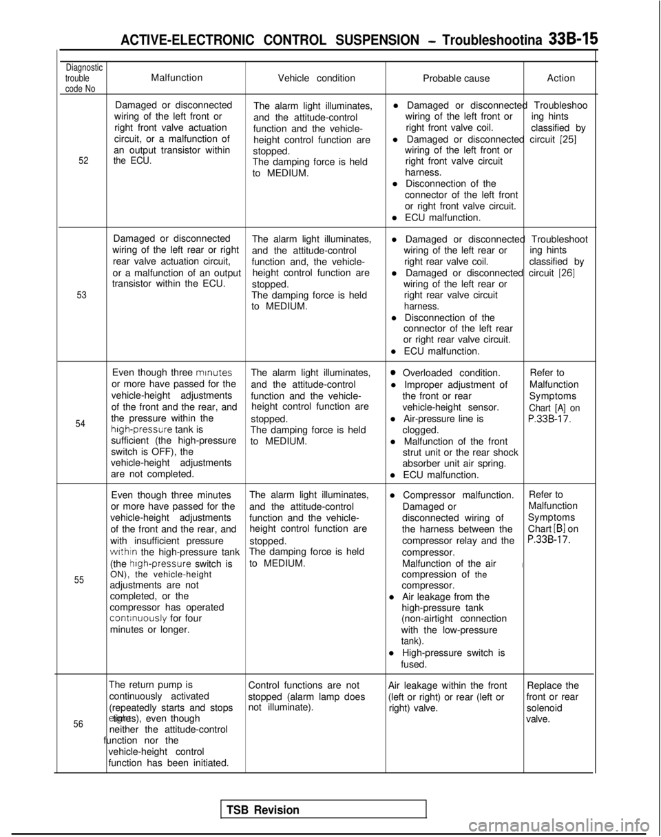
Diagnostic
trouble
code NoMalfunction Vehicle condition Probable causeAction
52
Damaged or disconnected
The alarm light illuminates, l Damaged or disconnected Troubleshoo
wiring of the left front or and the attitude-control wiring of the left front or
ing hints
right front valve actuation function and the vehicle- right front valve coil.
classified by
circuit, or a malfunction of height control function arel Damaged or disconnected circuit
[25]an output transistor within
stopped. wiring of the left front orthe ECU.The damping force is held
right front valve circuit
to MEDIUM. harness.
l Disconnection of the connector of the left front
or right front valve circuit.
l ECU malfunction.
53
Damaged or disconnected The alarm light illuminates,
wiring of the left rear or right l Damaged or disconnected Troubleshoot
and the attitude-control wiring of the left rear or
rear valve actuation circuit, ing hints
function and, the vehicle- right rear valve coil.
classified by
or a malfunction of an output height control function are
transistor within the ECU. l Damaged or disconnected circuit
[26]
stopped.
wiring of the left rear or
The damping force is held right rear valve circuit
to MEDIUM.
harness.
l Disconnection of the connector of the left rear
or right rear valve circuit.
l ECU malfunction.
54
55
Even though three mrnutes
The alarm light illuminates,0 Overloaded condition. Refer to
or more have passed for the and the attitude-control l Improper adjustment ofMalfunction
vehicle-height adjustments function and the vehicle- the front or rear
of the front and the rear, and Symptoms
height control function are vehicle-height sensor.
Chart [A] onthe pressure within thestopped.l Air-pressure line isP.33B-17.high-pressure
tank is
The damping force is held
sufficient (the high-pressure clogged.
to MEDIUM. l Malfunction of the front
switch is OFF), the strut unit or the rear shock
vehicle-height adjustments absorber unit air spring.
are not completed. l ECU malfunction.
Even though three minutes The alarm light illuminates,
l Compressor malfunction.Refer to
or more have passed for the and the attitude-control Damaged orMalfunction
vehicle-height adjustments function and the vehicle- disconnected wiring ofSymptoms
of the front and the rear, and height control function are
the harness between theChart
LB1 on
with insufficient pressure stopped. compressor relay and the
P.33B-17.
withtn the high-pressure tankThe damping force is held
compressor.
(the high-pressure
switch isto MEDIUM.
Malfunction of the air
iON), the vehicle-height compression of the
adjustments are not compressor.
completed, or the l Air leakage from the
compressor has operated
continuously for four high-pressure tank
minutes or longer. (non-airtight connection
with the low-pressure
tank).
l High-pressure switch is fused.
The return pump is Control functions are not Air leakage within the frontReplace the
continuously activated stopped (alarm lamp does (left or right) or rear (left orfront or rear
(repeatedly starts and stops not illuminate).
right) valve.solenoid
56erght times), even though
valve.
neither the attitude-control
function nor the
vehicle-height control
function has been initiated.
TSB Revision
Page 974 of 1273
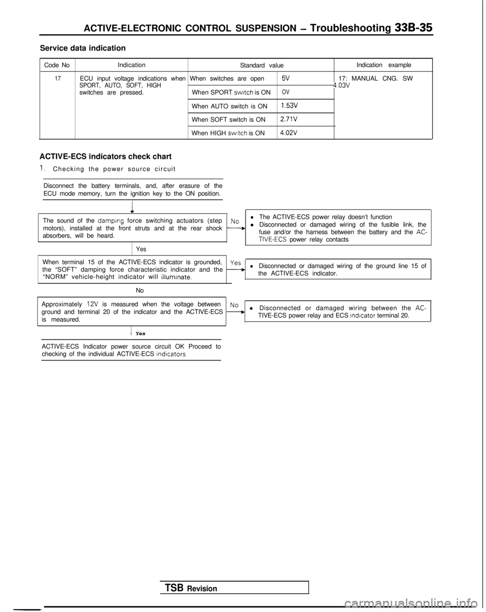
ACTIVE-ELECTRONIC CONTROL SUSPENSION - Troubleshooting 33B-35
Service data indication
Code No Indication
Standard value
17ECU input voltage indications when When switches are openSPORT, AUTO, SOFT, HIGH5V
switches are pressed.When SPORT switch
is ONOV
When AUTO switch is ON1.53v
When SOFT switch is ON 2.71V
When HIGH swrtch
is ON 4.02V
ACTIVE-ECS indicators check chart
1.Checking the power source circuit
Disconnect the battery terminals, and, after erasure of the
ECU mode memory, turn the ignition key to the ON position.
1
Indication example
17: MANUAL CNG. SW
4.03v
The sound of the damplng force switching actuators (steplNoThe ACTIVE-ECS power relay doesn’t function
motors), installed at the front struts and at the rear shock
--+l Disconnected or damaged wiring of the fusible link, the
absorbers, will be heard. fuse and/or the harness between the battery and the AC-TIVE-ECS power relay contacts
Yes
When terminal 15 of the ACTIVE-ECS indicator is grounded,yes
the “SOFT” damping force characteristic indicator and the -lDisconnected or damaged wiring of the ground line 15 of
“NORM” vehicle-height indicator will
illuminate.the ACTIVE-ECS indicator.
No
Approximately
12V is measured when the voltage betweenNo
ground and terminal 20 of the indicator and the ACTIVE-ECS --+l Disconnected or damaged wiring between the AC-
is measured. TIVE-ECS power relay and ECS Indicator
terminal 20.
I Yes
TSB Revision
-. ACTIVE-ECS Indicator power source circuit OK Proceed to
checking of the individual ACTIVE-ECS
lndlcators
Page 1137 of 1273
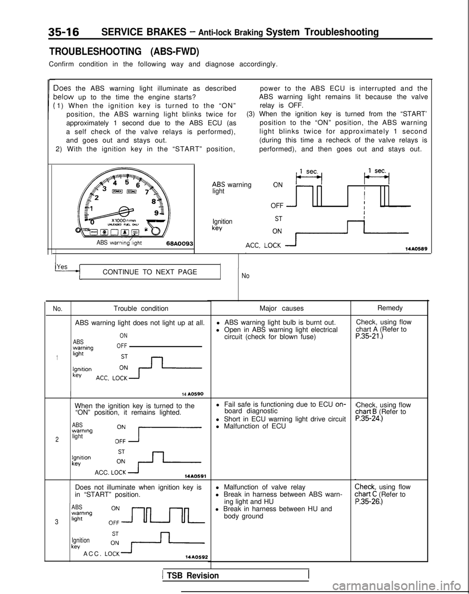
35-16SERVICE BRAKES - Anti-lock Braking System Troubleshooting
TROUBLESHOOTING (ABS-FWD)
Confirm condition in the following way and diagnose accordingly.
Ioes the ABS warning light illuminate as describedpower to the ABS ECU is interrupted and the
lelow up to the time the engine starts?ABS warning light remains lit because the valve
1) When the ignition key is turned to the “ON” relay is OFF.
position, the ABS warning light blinks twice for (3) When the ignition key is turned from the “START’
approximately 1 second due to the ABS ECU (as position to the “ON” position, the ABS warning
a self check of the valve relays is performed), light blinks twice for approximately 1 second
and goes out and stays out. (during this time a recheck of the valve relays is
2) With the ignition key in the “START” position, performed), and then goes out and stays out.
ABS warning
,,lseq (se+
lightII
OFF -I
Ignitionkey
ABS warnmg/;,ght68A009314A0589
YAS rICONTINUE TO NEXT PAGENo
No.
Trouble condition
ABS warning light does not light up at all.
ABSwarnina
ON
OFF
1light -
lgnltionkey
I14 A0590
When the ignition key is turned to the l Fail safe is functioning due to ECU on-
“ON” position, it remains lighted. board diagnostic
ABSwarning
2lightOZ7
l Short in ECU warning light drive circuit
l Malfunction of ECU
lgnitlonkev
ACC. LOi+14A0591
Does not illuminate when ignition key is
in “START” position.
ABSwarning
3light
Ignition
key ACC. LO:+14AO592
Major causes
l ABS warning light bulb is burnt out.
l Open in ABS warning light electrical circuit (check for blown fuse)
l Malfunction of valve relay
l Break in harness between ABS warn- ing light and HU
l Break in harness between HU and body ground Remedy
Check, using flow
chart A (Refer to
P.35-21.)
Check, using flowchart B (Refer toP.35-24.)
Check, using flow:hart C (Refer to ‘.35-26.)
1 TSB Revision
Page 1155 of 1273
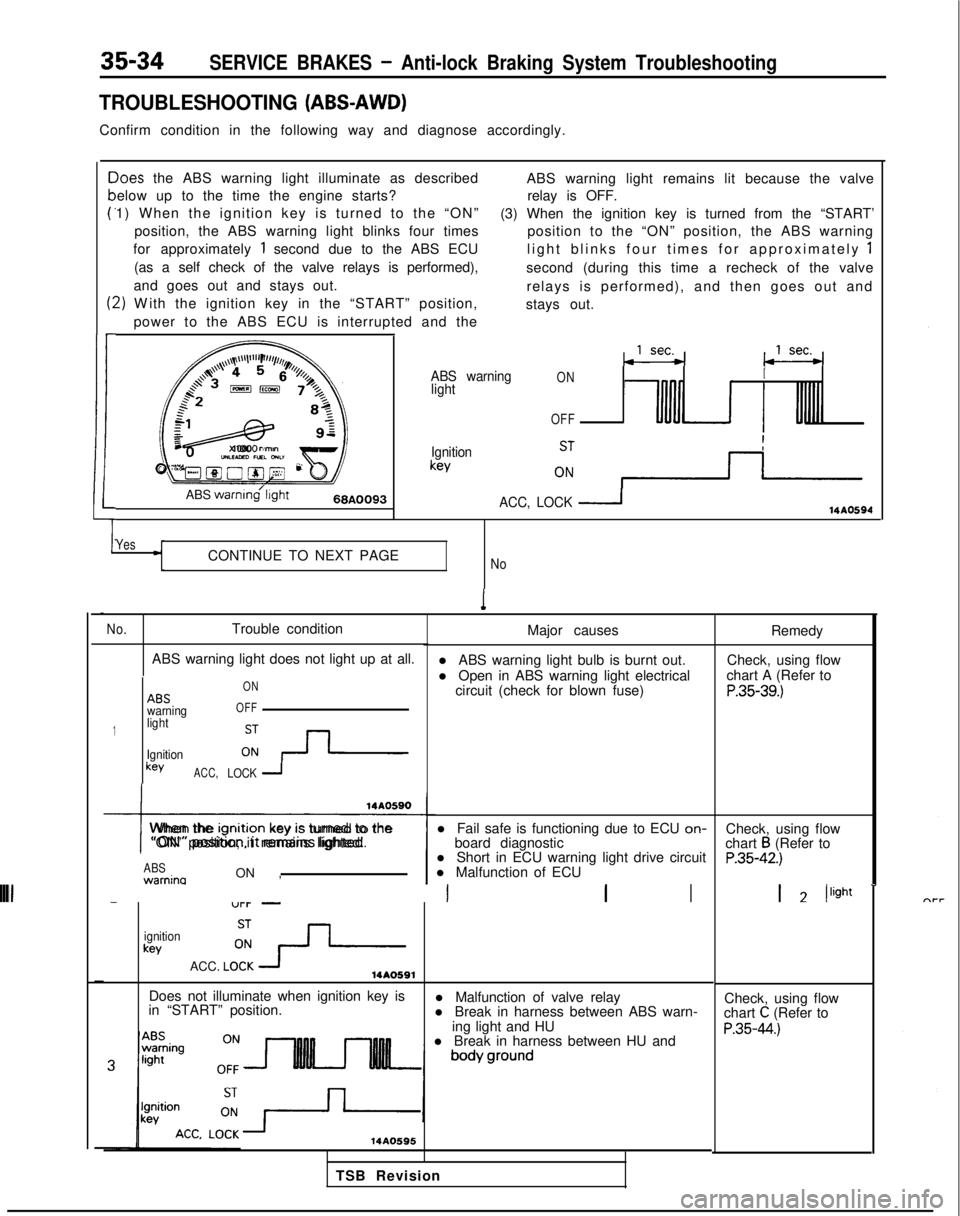
35-34SERVICE BRAKES - Anti-lock Braking System Troubleshooting
TROUBLESHOOTING (ABS-AWD)
Confirm condition in the following way and diagnose accordingly.
c
P
t:
1
-)oes
the ABS warning light illuminate as described
elow up to the time the engine starts?
1) When the ignition key is turned to the “ON”
position, the ABS warning light blinks four times
for approximately
1 second due to the ABS ECU
(as a self check of the valve relays is performed),
and goes out and stays out.
2) W
ith the ignition key in the “START” position,
power to the ABS ECU is interrupted and the ABS warning light remains lit because the valve
relay is OFF.
(3) When the ignition key is turned from the “START’ position to the “ON” position, the ABS warning
light blinks four times for approximately
1
second (during this time a recheck of the valve
relays is performed), and then goes out and
stays out.
,,,\~~\l’l”“F’,r//,,,l/,,
a+’4 4 5r’o, (j /z$$+3,,,,%&73,
:
f=&L-gy
82
1cJz
x 1000
rimonUILEAED nxL GNL”Oyg@O@~ 2F
ABS
warnmg’l~ght66A0093
ABS warning
lightONI
OFF
Ignitionkey
ACC, LOCK
114AO594
YesCONTINUE TO NEXT PAGENo
1
No.Trouble condition
ABS warning light does not light up at all.
1
ABSwarning
light
Ignition
keyACC, ON
OFFLOCK 1
I
When the lgnltlon
key IS turned to the
“ON” position, it remains lighted.
ABS warnina
ON , l Short in ECU warning light drive circuit
l Malfunction of ECU
-“l-l- -III
ignitionkey
ACC. LO!?-14AO591
Major causes
l ABS warning light bulb is burnt out.
l Open in ABS warning light electrical circuit (check for blown fuse)
l Fail safe is functioning due to ECU on-
board diagnostic
Does not illuminate when ignition key is
in “START” position. l Malfunction of valve relay
l Break in harness between ABS warn-
ing light and HU
l Break in harness between HU and
14AO595
Remedy
Check, using flow
chart A (Refer to
P.35-39.)
Check, using flow
chart B (Refer toP.35-42.)
1 2 /light
-
Check, using flow
chart C (Refer to
P.35-44.)
TSB Revision