1989 MITSUBISHI GALANT ABS
[x] Cancel search: ABSPage 5 of 1273
GENERAL - How to Use This Manual00-3
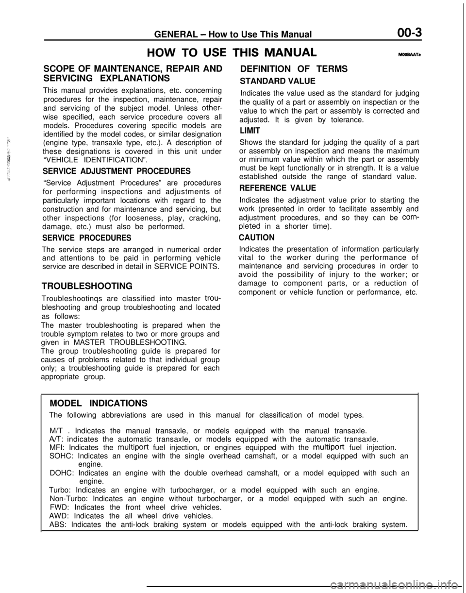
HOW
TO USE THIS MANUALMOOBMTO
SCOPE OF MAINTENANCE, REPAIR AND
DEFINITION OF TERMS
SERVICING EXPLANATIONS STANDARD VALUE
This manual provides explanations, etc. concerning procedures for the inspection, maintenance, repair
and servicing of the subject model. Unless other-
wise specified, each service procedure covers all models. Procedures covering specific models are
identified by the model codes, or similar designation
(engine type, transaxle type, etc.). A description of
these designations is covered in this unit under “VEHICLE IDENTIFICATION”.
SERVICE ADJUSTMENT PROCEDURES
“Service Adjustment Procedures” are procedures
for performing inspections and adjustments of
particularly important locations with regard to the
construction and for maintenance and servicing, but
other inspections (for looseness, play, cracking,
damage, etc.) must also be performed.
SERVICE PROCEDURES
The service steps are arranged in numerical order and attentions to be paid in performing vehicleservice are described in detail in SERVICE POINTS.
TROUBLESHOOTING
Troubleshootinqs are classified into master trou-
bleshooting and group troubleshooting and located
as follows:
The master troubleshooting is prepared when the trouble symptom relates to two or more groups and
given in MASTER TROUBLESHOOTING.
The group troubleshooting guide is prepared for causes of problems related to that individual group
only; a troubleshooting guide is prepared for each
appropriate group. Indicates the value used as the standard for judging
the quality of a part or assembly on inspectian or the
value to which the part or assembly is corrected and
adjusted. It is given by tolerance.
LIMIT
Shows the standard for judging the quality of a part
or assembly on inspection and means the maximum
or minimum value within which the part or assembly must be kept functionally or in strength. It is a value
established outside the range of standard value.
REFERENCE VALUE
Indicates the adjustment value prior to starting the
work (presented in order to facilitate assembly and adjustment procedures, and so they can be
com- pleted
in a shorter time).
CAUTION
Indicates the presentation of information particularly
vital to the worker during the performance of maintenance and servicing procedures in order to
avoid the possibility of injury to the worker; or
damage to component parts, or a reduction of
component or vehicle function or performance, etc.
MODEL INDICATIONS
The following abbreviations are used in this manual for classification o\
f model types.
M/T . Indicates the manual transaxle, or models equipped with the manual\
transaxle.
A/T: indicates the automatic transaxle, or models equipped with the automati\
c transaxle.
MFI: Indicates the multiport
fuel injection, or engines equipped with the
multiport fuel injection.
SOHC: Indicates an engine with the single overhead camshaft, or a model \
equipped with such an engine.
DOHC: Indicates an engine with the double overhead camshaft, or a model \
equipped with such an engine.
Turbo: Indicates an engine with turbocharger, or a model equipped with s\
uch an engine. Non-Turbo: Indicates an engine without turbocharger, or a model equipped\
with such an engine.FWD: Indicates the front wheel drive vehicles.
AWD: Indicates the all wheel drive vehicles. ABS: Indicates the anti-lock braking system or models equipped with the \
anti-lock braking system.
Page 33 of 1273
GENERAL - Master Troubleshooting
00-31
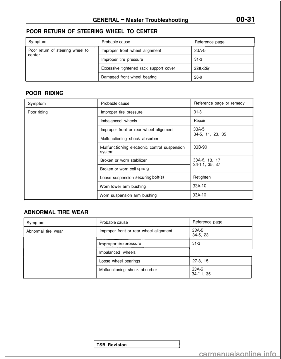
POOR RETURN OF STEERING WHEEL TO CENTER
Symptom
Probable cause Reference page
’Poor return of steering wheel to
Improper front wheel alignment33A-5center
Improper tire pressure31-3
Excessive tightened rack support cover 37A-35, 36, 37
Damaged front wheel bearing
26-9
POOR RIDING
Symptom
Poor riding Probable cause
Reference page or remedy
Improper tire pressure
31-3
lmbalanced wheelsRepair
Improper front or rear wheel alignment33A-5
34-5, 11, 23, 35
Malfunctioning shock absorber Malfunctioning
electronic control suspension
33B-90system
Broken or worn stabilizer
33A-6. 13, 1734-l 1, 35, 37
Broken or worn coil spri#ng
Loose suspension secuiring bolt(s)
Retighten
Worn lower arm bushing
33A-10
Worn suspension arm bushing 33A-IO
TSB Revision
ABNORMAL TIRE WEAR
Symptom
Abnormal tire wear Probable cause
Improper front or rear wheel alignment Reference page
33A-534-5, 23
131-3
lmbalanced wheelsII
Loose wheel bearings
27-3, 15
Malfunctioning shock absorber
33A-634-l 1, 35
Page 34 of 1273
00-32
GENERAL - Master Troubleshooting
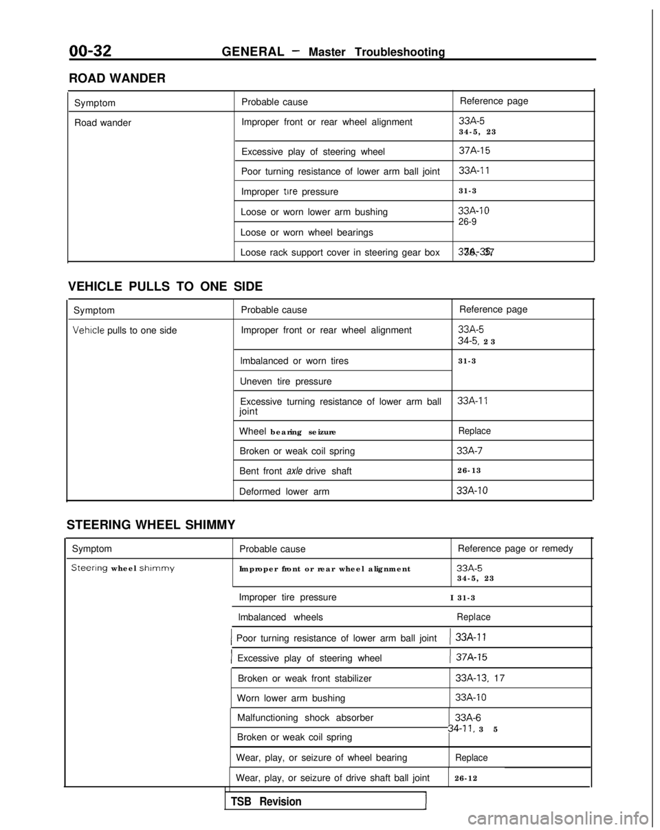
ROAD WANDER Symptom
Road wander Probable cause
Improper front or rear wheel alignment Reference page
33A-534-5, 23
Excessive play of steering wheel
37A-15
Poor turning resistance of lower arm ball joint33A-11
Improper tire pressure 31-3
Loose or worn lower arm bushing
33A-10
26-9
Loose or worn wheel bearings
Loose rack support cover in steering gear box 37A-35. 36, 37
VEHICLE PULLS TO ONE SIDE Symptom Probable cause Reference page
Vehrcle pulls to one side
Improper front or rear wheel alignment33A-5
34-5. 2
3
lmbalanced or worn tires 31-3
Uneven tire pressure Excessive turning resistance of lower arm ball
33A-17joint
Wheel bearing seizure
Replace
Broken or weak coil spring33A-7
Bent front axle drive shaft 26-13
Deformed lower arm
33A-10
STEERING WHEEL SHIMMY
Symptom
Steerlng wheel shlmmy
Probable cause
Improper front or rear wheel alignment Reference page or remedy
33A-534-5, 23
Improper tire pressure I 31-3
lmbalanced wheels
Replace
1 Poor turning resistance of lower arm ball joint) 33A-11
] Excessive play of steering wheel) 37A-15
Broken or weak front stabilizer
Worn lower arm bushing33A-13. 17
33A-10
Malfunctioning shock absorber
Broken or weak coil spring
Wear, play, or seizure of wheel bearing33A-6
34-11, 3
5
Replace
Wear, play, or seizure of drive shaft ball joint
26-12
TSB Revision1
Page 35 of 1273
GENERAL - Master Troubleshootinn
00-33
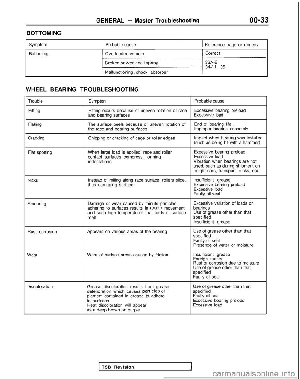
BOTTOMING Symptom Probable cause
1 Reference page or remedy
Bottoming
Malfunctioning shock absorber
WHEEL BEARING TROUBLESHOOTING TroublePitting
Flaking
Cracking
Sympton Probable cause
Pitting occurs because of uneven rotation of race Excessive bearing preload
and bearing surfaces Excessrve
load
The surface peels because of uneven rotation of
End of bearing life ,
the race and bearing surfaces Improper bearing assembly
Chipping or cracking of cage or roller edges Impact when
beanng was installed
(such as being hit with a hammer)
Flat spotting When large load is applied, race and roller
contact surfaces compress, formingindentations Excessive bearing preload
Excessive load
Vibration when bearings are not used, such as during shipment on
freight cars, transport trucks, etc.
NicksInstead of roiling along race surface, rollers slide, insufficient grease
thus damaging surface Excessive bearing preload
Excessive load
Faulty oil seal
Smearing Damage or wear caused by minute particles Excessive variation of loads on
adhering to surfaces results in
rolugh movement bearings
and such high temperatures that parts of surface Use of grease other than that
melt specified
Insufficient grease
Rust, corrosion Appears on various areas of the bearing Use of grease other than that
specified Faulty oil seal
Presence of water or moisture
WearWear of surface areas caused by friction Insufficient grease
Foreign matter
Rust or corrosion due to moisture
Use of grease other than that
specified
Faulty oil seal Irscoloration
Grease discoloration results from grease
deterioration which causes partic:les
of
pigment contained in grease to adhere
to surfaces Heat discoloration will appear
as a deep brown on purple Use of grease other than that
specified
Faulty oil seal Excessive bearing preload
Excessive load
TSB Revision
Page 50 of 1273
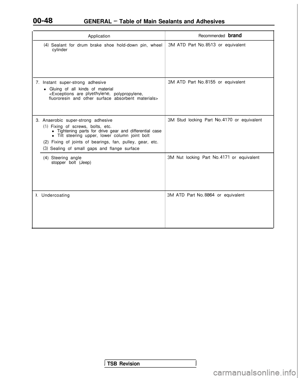
00-48GENERAL - Table of Main Sealants and Adhesives
Application
Recommended brand
(4) Sealant for drum brake shoe hold-down pin, wheel 3M
ATD Part No.8513
or equivalent
cylinder
7. Instant super-strong adhesive l Gluing of all kinds of material 3M
ATD Part No.8155
or equivalent
fluororesin and other surface absorbent materials>
3. Anaerobic super-strong adhesive
(I) Fixing of screws, bolts, etc. 3M
Stud locking Part No.4170
or equivalent
l Tightening parts for drive gear and differential case
l Tilt steering upper, lower column joint bolt
(2) Fixing of joints of bearings, fan, pulley, gear, etc.
(3) Sealing of small gaps and flange surface
(4) Steering angle 3M
Nut locking Part
No.4171 or equivalent
stopper bolt (Jeep)
3. Undercoating 3M
ATD Part No.8864
or equivalent
1 TSB Revision
Page 195 of 1273
FUEL SYSTEM
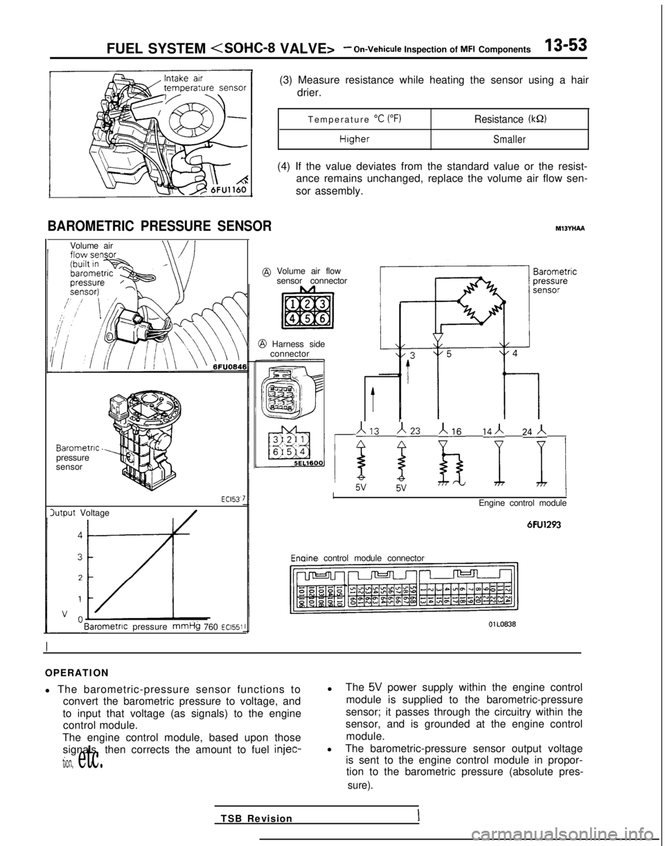
BAROMETRIC PRESSURE SENSOR
Volume air
Barometric.pressure
sensor
lutput Voltage ECl53.
Barometnc
pressure
mmHg 760 ~~1551
(3) Measure resistance while heating the sensor using a hair
drier.
Temperature
“C (“F)Resistance (kQ)
HigherSmaller
(4) If the value deviates from the standard value or the resist-
ance remains unchanged, replace the volume air flow sen-
sor assembly.
MlBYHAA
@ Volume air flow sensor connector
@ Harness sideconnector
t
113 j23 b ‘I 24j i
IEngine control module
6FU1293 Enaine
control module connector
OlL0838
OPERATION
l The barometric-pressure sensor functions to
convert the barometric pressure to voltage, and
to input that voltage (as signals) to the engine control module.
The engine control module, based upon those signals, then corrects the amount to fuel injec-
tion, etc.
l
The 5V power supply within the engine control
module is supplied to the barometric-pressure
sensor; it passes through the circuitry within the
sensor, and is grounded at the engine control
module.
l The barometric-pressure sensor output voltage
is sent to the engine control module in propor-tion to the barometric pressure (absolute pres-
sure).
TSB RevisionI
Page 390 of 1273
13-248FUEL SYSTEM
(8) Switch OFF the ignition switch.
(9) If the scan tool was not used, disconnect the jumper wire from the diagnostic test mode control terminal. (10)Disconnect
the jumper wire from the terminal for adjust-
ment of ignition timing, and return the connector to its
original condition.
(11
)Start the engine again and let it run at idle speed for about
ten minutes; check to be sure that the idling condition is
normal.
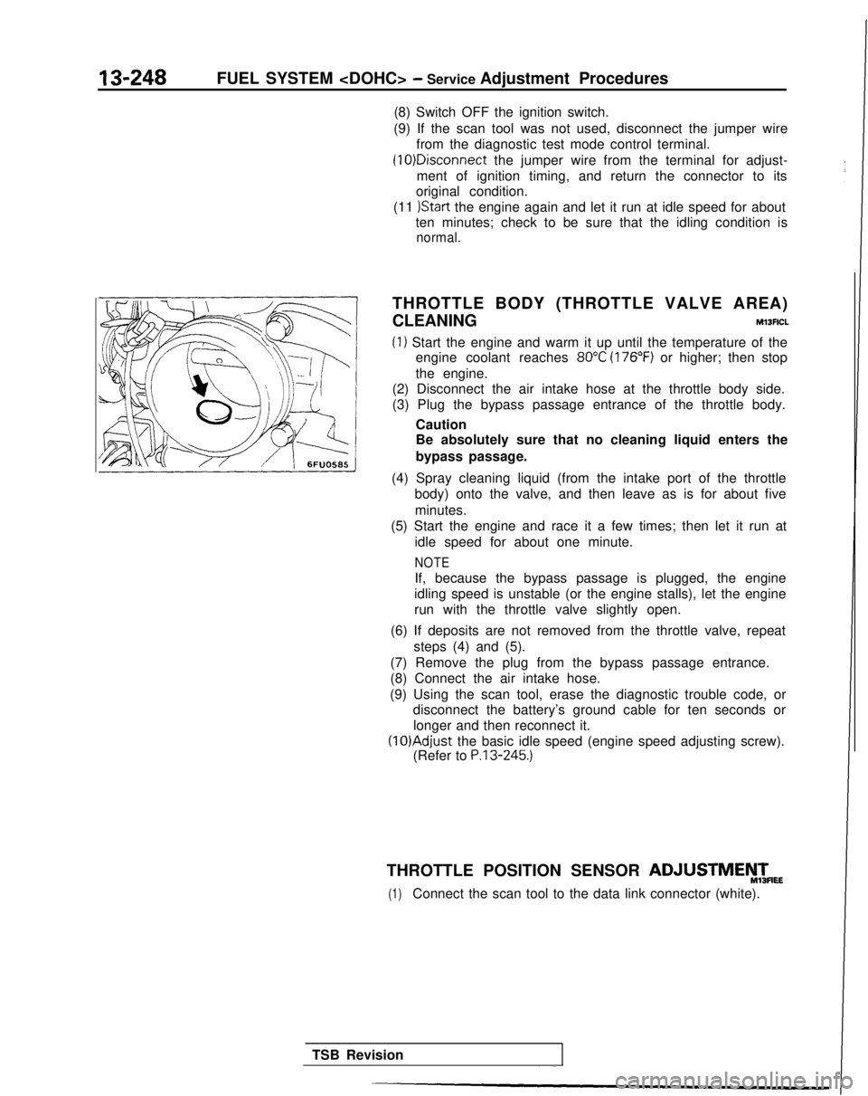
THROTTLE BODY (THROTTLE VALVE AREA)
CLEANING
Ml3ACL
(1) Start the engine and warm it up until the temperature of the engine coolant reaches
80°C (176°F) or higher; then stop
the engine.
(2) Disconnect the air intake hose at the throttle body side.
(3) Plug the bypass passage entrance of the throttle body.
Caution
Be absolutely sure that no cleaning liquid enters the
bypass passage.
(4) Spray cleaning liquid (from the intake port of the throttle body) onto the valve, and then leave as is for about five
minutes.
(5) Start the engine and race it a few times; then let it run at
idle speed for about one minute.
NOTE
If, because the bypass passage is plugged, the engine
idling speed is unstable (or the engine stalls), let the engine
run with the throttle valve slightly open.
(6) If deposits are not removed from the throttle valve, repeat steps (4) and (5).
(7) Remove the plug from the bypass passage entrance.
(8) Connect the air intake hose.
(9) Using the scan tool, erase the diagnostic trouble code, or disconnect the battery’s ground cable for ten seconds or
longer and then reconnect it. (lO)Adjust
the basic idle speed (engine speed adjusting screw).
(Refer to
P.13-245.)
THROTTLE POSITION SENSOR ADJUSTMEyTmEE
(1)Connect the scan tool to the data link connector (white).
TSB Revision
Page 408 of 1273
13-266FUEL SYSTEM
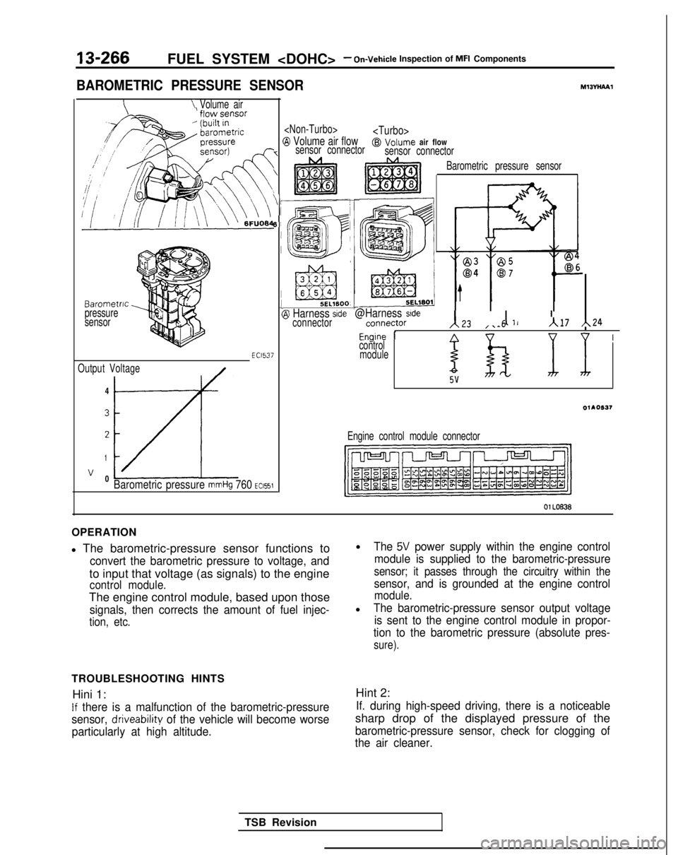
BAROMETRIC PRESSURE SENSORMl3VHPYPl
\ Volume air
Barometric
pressure
sensor
Output Voltage
/-4
3
2
1
v 0LzLBarometric pressure mmHg 760 ~~1551
EC1537
(
7
\
‘i
6!
I
I1(
5EL1600, L-@I Harness sideconnector@Harness sidernnn~rtnr131 11, I ’““, ,. Iv-.-.,\L4 ,\-5A17 h24
Fnnine 1Anv uI
Barometric pressure sensor
-“J -control
module
I
OllO537
Engine control module connector
01 LOB38
OPERATION
l The barometric-pressure sensor functions to
convert the barometric pressure to voltage, and
to input that voltage (as signals) to the engine
control module.
The engine control module, based upon those
signals, then corrects the amount of fuel injec-
tion, etc.
TROUBLESHOOTING HINTS Hini 1:
If there is a malfunction of the barometric-pressure
sensor,
driveability of the vehicle will become worse
particularly at high altitude.
lThe 5V power supply within the engine control
module is supplied to the barometric-pressure
sensor; it passes through the circuitry within the
sensor, and is grounded at the engine control
module.
lThe barometric-pressure sensor output voltage is sent to the engine control module in propor-
tion to the barometric pressure (absolute pres-
sure).
Hint 2:
If. during high-speed driving, there is a noticeable
sharp drop of the displayed pressure of the
barometric-pressure sensor, check for clogging of
the air cleaner.
TSB Revision