1989 MITSUBISHI GALANT kickdown
[x] Cancel search: kickdownPage 689 of 1273
23-1
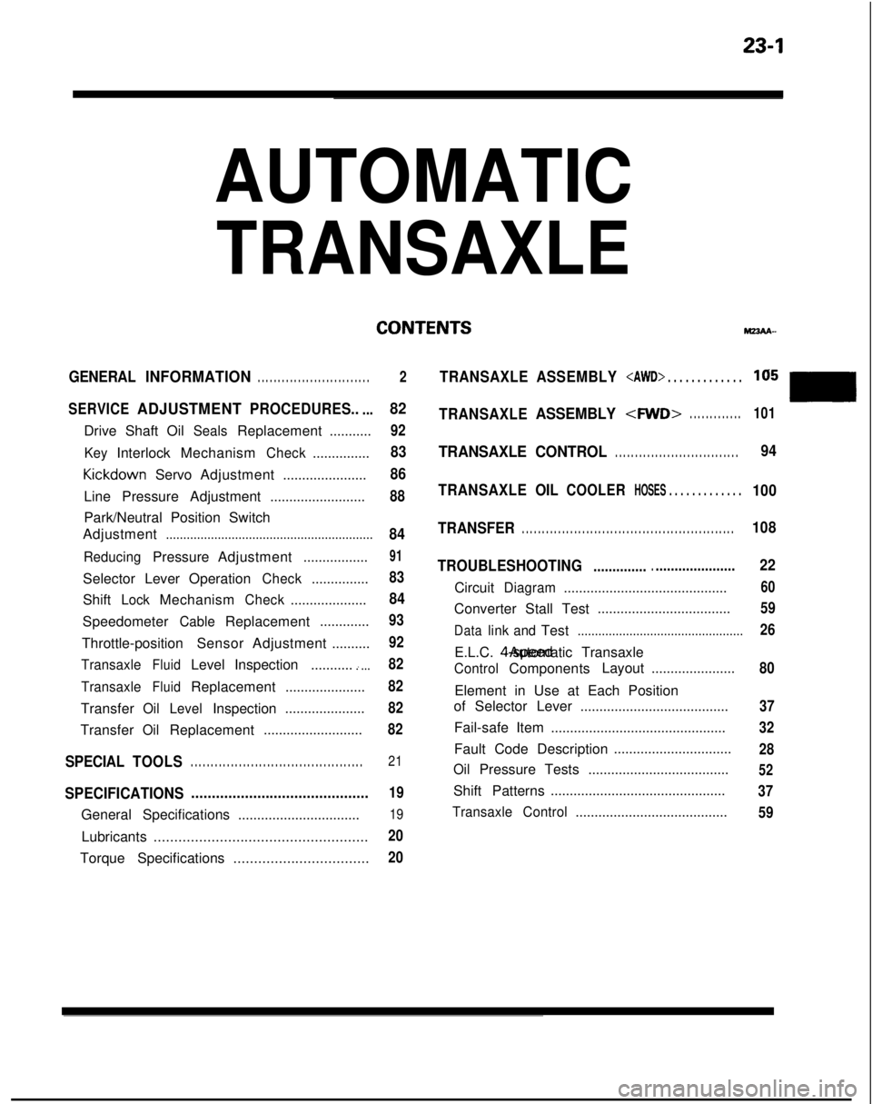
AUTOMATIC
TRANSAXLE
CONTENTShl23AA-
GENERALINFORMATION. . . . . . . . . . . . . . . . . . . . . . . . . . . .
SERVICEADJUSTMENTPROCEDURES.....
Drive Shaft OilSealsReplacement...........
KeyInterlockMechanismCheck............... Kickdown
ServoAdjustment ......................
Line Pressure Adjustment .........................
Park/Neutral Position Switch
Adjustment
............................................................
ReducingPressure Adjustment .................
Selector LeverOperation
Check...............
Shift
LockMechanismCheck....................
Speedometer
CableReplacement .............
Throttle-position Sensor Adjustment ..........
TransaxleFluidLevelInspection ...........i...
TransaxleFluidReplacement .....................
Transfer
Oil LevelInspection .....................
Transfer
OilReplacement ..........................
SPECIAL
TOOLS. . . . . . . . . . . . . . . . . . . . . . . . . . . . . . . . . . . . \
. . . . . . .21
SPECIFICATIONS ...........................................19
General Specifications
................................19
Lubricants....................................................20
Torque Specifications .................................20
2TRANSAXLEASSEMBLY
82
92
83
86
88
84
91
83
84
93
92
82
82
82
82
TRANSAXLEASSEMBLY
TRANSAXLE CONTROL. . . . . . . . . . . . . . . . . . . . . . . . . . . . . . .94
TRANSAXLE OIL
COOLERHOSES . . . . . . . . . . . . .100
TRANSFER
. . . . . . . . . . . . . . . . . . . . . . . . . . . . . . . . . . . . \
. . . . . . . . . . . . . . . . .108
TROUBLESHOOTING
....................................
CircuitDiagram...........................................
Converter Stall Test ...................................
Datalink
andTest................................................
E.L.C. 4-speed Automatic Transaxle
ControlComponents
Layout
......................
Element in Use at Each Position
of Selector Lever .......................................
Fail-safe Item ..............................................
Fault Code Description ...............................
OilPressure Tests
.....................................
Shift Patterns ..............................................
Transaxle
Control........................................
22
60
59
26
80
37
32
28
52
37 59
Page 726 of 1273
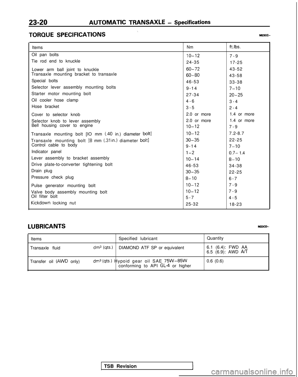
23-20AUTOMATIC TRANSAXLE
- Specifications
\TORQUE
SPECIFICATIONSMz3cc-
ItemsNmft.lbs.
Oil pan bolts10-127-
9
Tie rod end to knuckle 24-3517-25
Lower arm ball joint to knuckle
60-7243-52
Transaxle mounting bracket to transaxle
60-8043-58
Special bolts 46-5333-38
Selector lever assembly mounting bolts 9-1
4
7-10
Starter motor mounting bolt
27-3420-25
Oil cooler hose clamp4-
6
3-4
Hose bracket 3-52-4
Cover to selector knob 2.0 or more
1.4 or more
Selector knob to lever assembly 2.0 or more
1.4 or more
Bell housing cover to engine
10-127-
9
Transaxle mounting bolt [IO mm
(.40 in.) diameter bolt110-127.2-8.7
Transaxle mounting bolt
[8 mm (.31 In.) diameter bolt130-3522-25
Control cable to body 9-1
4
7-10
Indicator panell-20.7- 1.4
Lever assembly to bracket assembly10-148-10
Drive plate-to-converter tightening bolt
46-5334-38
Drain plug
30-3522-25
Pressure check plug
8-106-
7
Pulse generator mounting bolt
IO-127-
9
Valve body assembly mounting bolt
IO-127-
9
Oil filter bolt 5-74-5Kickdown
locking nut
25-3218-23LUBRICANTS
MPCD--
Items
Transaxle fluid Specified lubricant
Quantity
dm3 (qts.)DIAMOND ATF SP or equivalent6.1 (6.4): FWD AA
6.5 (6.9): AWD PJT
Transfer oil (AWD only)dm3 (qts.) Hypoid gear oil SAE 75W-85Wconforming to API GL-4 or higher0.6 (0.6)
TSB Revision
Page 730 of 1273
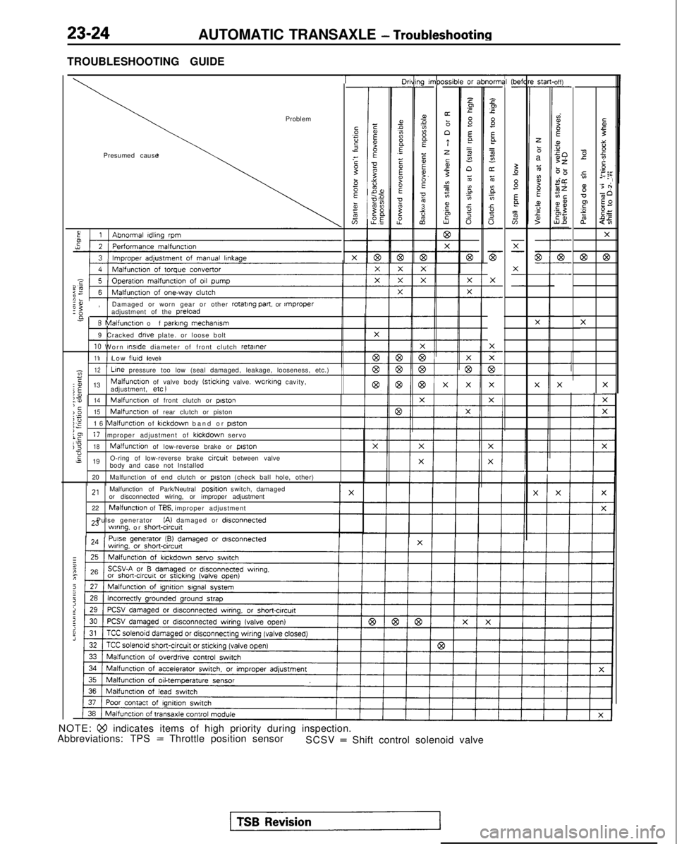
23-24AUTOMATIC TRANSAXLE - Troubleshooting
TROUBLESHOOTING GUIDE
T-----lO"ni31-
z.Ip.c
8Ea
=
s"oz6
E.
;In.ci!
a
-
F
X
-
-
X
77
c-
X
F-
i-
1g I”,PC-
ms?A
E
EEF.E053%
2
xsib-or z-
Pp
s E
a=g
n6
BE0.cY.20 (befl
-St.3-
zbaz
ti?BEa,fs
off)-
dI?f
s50>z6-0vi@zEiECE$,aZ5%-
-
7-
-
Ibr
I
Problem
Presumed causeTi3::-0 e
2Ts
y.=:,02 EF
g'5 +
v-60
F $2
s?
$=
2
$5
X
@63
X
X
I’
-
57-
-X-
-
G-- X
-
-X
X
e:,
Damaged or worn gear or other rotating part.
or rnproperadjustment of the preload
n
8 Malfunction of
parklng
mechamsm
9 Cracked drive plate. or loose bolt
10 Worn InsIde
diameter of front clutch retainer
11Low flutd
level
X
-
1z12 Line
pressure too low (seal damaged, leakage, looseness, etc.)E:o 13Malfunctton of valve body (sticking valve. worktng cavity,
j$adjustment, etc )XX
I
:?I14‘cMalfunction of front clutch or poston
)_O15Malfunction of rear clutch or pistoni;;E16 Malfunction of klckdown band or piston
le17 Improper adjustment of kickdown servoj318Malfunction of low-reverse brake or piston-6s 19 O-ring of low-reverse brake circuit between valve
body and case not Installed
20 Malfunction of end clutch or
piston (check ball hole, other)
2,Malfunction of Park/Neutral positjon switch, damaged
or disconnected wiring, or improper adjustment
22
Malfunction of TPS. or improper adjustment
23 Pulse generator
(A) damaged or disconnectedwlnng. or short&cut^
NOTE: Qo indicates items of high priority during inspection.
Abbreviations: TPS = Throttle position sensor SCSV = Shift control solenoid valve
Page 734 of 1273
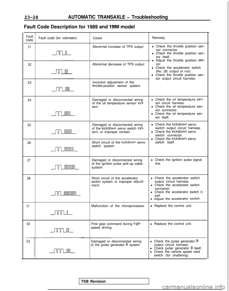
23-28AUTOMATIC TRANSAXLE - Troubleshooting ’
Fault Code Description for 1989 and 1990 model
FaultcodeFault code (for voltmeter)CauseRemedy
21Abnormal increase of TPS output
l Check the throttle position sen-
sor connector.
l Check the throttle position sen-
sor itself.
22
23
- l Adjust the throttle position sen-
Abnormal decrease of TPS outputsor.l Check the accelerator switch (No. 28: output or not).
l Check the throttle position sen- sor output circuit harness.
Incorrect adjustment of the
throttle-position sensor system
24Damaged or disconnected wiring
of the oil temperature sensor sys-
tern
l Check the oil temperature sen-
sor circuit harness.
l Check the oil temperature sen-
sor connector.
l Check the oil temperature sen-
sor itself.
25
26
Damaged or disconnected wiring l Check the kickdown
servo
of the kickdown
servo switch sys-
switch output circuit harness. tern.
or improper contact l Check the kickdown
servo
switch connector.
l Check the kickdown
servo
Short circuit of the kickdown
servo switch itself.
switch system
27Damaged or disconnected wiring
of the ignition pulse pick-up cable
system l Check the ignition pulse signal
line.
28Short circuit of the accelerator
switch system or improper adjust-
ment l Check the accelerator switch
output circuit harness.
l Check the accelerator switch
connector.
l Check the accelerator switch it-
self.
31
l Adjust the accelerator switch.
Malfunction of the microprocessor l Replace the control unit.
32First gear command during hrgh-speed drivingl Replace the control unit.
Damaged or disconnected wiring
of the pulse generator
B system l Check the pulse generator Boutput circuit harness.
l Check pulse generator B itself.
l Check the vehicle speed reed
switch (for chattering).
TSB Revision
Page 735 of 1273
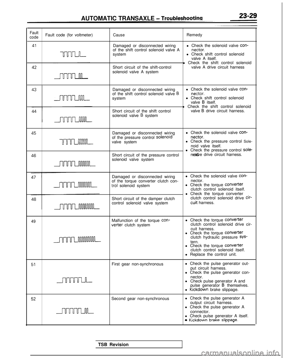
AUTOMATIC TRANSAXLE - Troubleshootina
Fault
codeFault code (for voltmeter)CauseRemedy
41
UUU-LJ-I-
Damaged or disconnected wiring l Check the solenoid valve con-
of the shift control solenoid valve A nectar.
system l Check shift control solenoid
valve A itself. 42
Short circuit of the shift-control
solenoid valve A system l Check the shift control solenoid
valve A drive circuit harness
Damaged or disconnected wiring l Check the solenoid valve con-
of the shift control solenoid valve
B nectar.
system l Check shift control solenoid
valve
B itself.
Short circuit of the shift control
solenoid valve
B system l Check the shift control solenoid
valve
B drive circuit harness. 45
Damaged or disconnected wiringl Check the solenoid valve con-
of the pressure control solenord nectar.
uuuLnnnM-valve system
l Check the pressure control Sole-
noid valve itself. 46
l Check the pressure control sole-
Short circuit of the pressure control noid valve drive circuit harness.
solenoid valve system
Damaged or disconnected wiring
of the torque converter clutch con- trol
solenoid system
Short circuit of the damper clutch
control solenoid valve system l Check the solenoid valve con-
nector.
l Check the torque COnVeIter
clutch control solenoid itself.
l Check the torque converter clutch control solenoid drive cir-
cuit harness.
49Malfunction of the torque
con-vetter clutch system
l Check the torque
Converterclutch control solenoid drive cir-
cuit harness.
l Check the torque
COnVeITerclutch hydraulic pressure SYS-
tern.
l Check the torque COnVerter
clutch control solenoid itself.
l Replace the control unit.
51First gear non-synchronous l Check the pulse generator out-
put circuit harness.
l Check the pulse generator con-
nector.
l Check pulse generator A and
pulse generator
B themselves.
l Kickdown
brake slippage.
52Second gear non-synchronous l Check the pulse generator A
output circuit harness.
l Check the pulse generator A
connector.
l Check pulse generator A itself. 0
Kickdown brake slippage.
TSB Revision
Page 736 of 1273
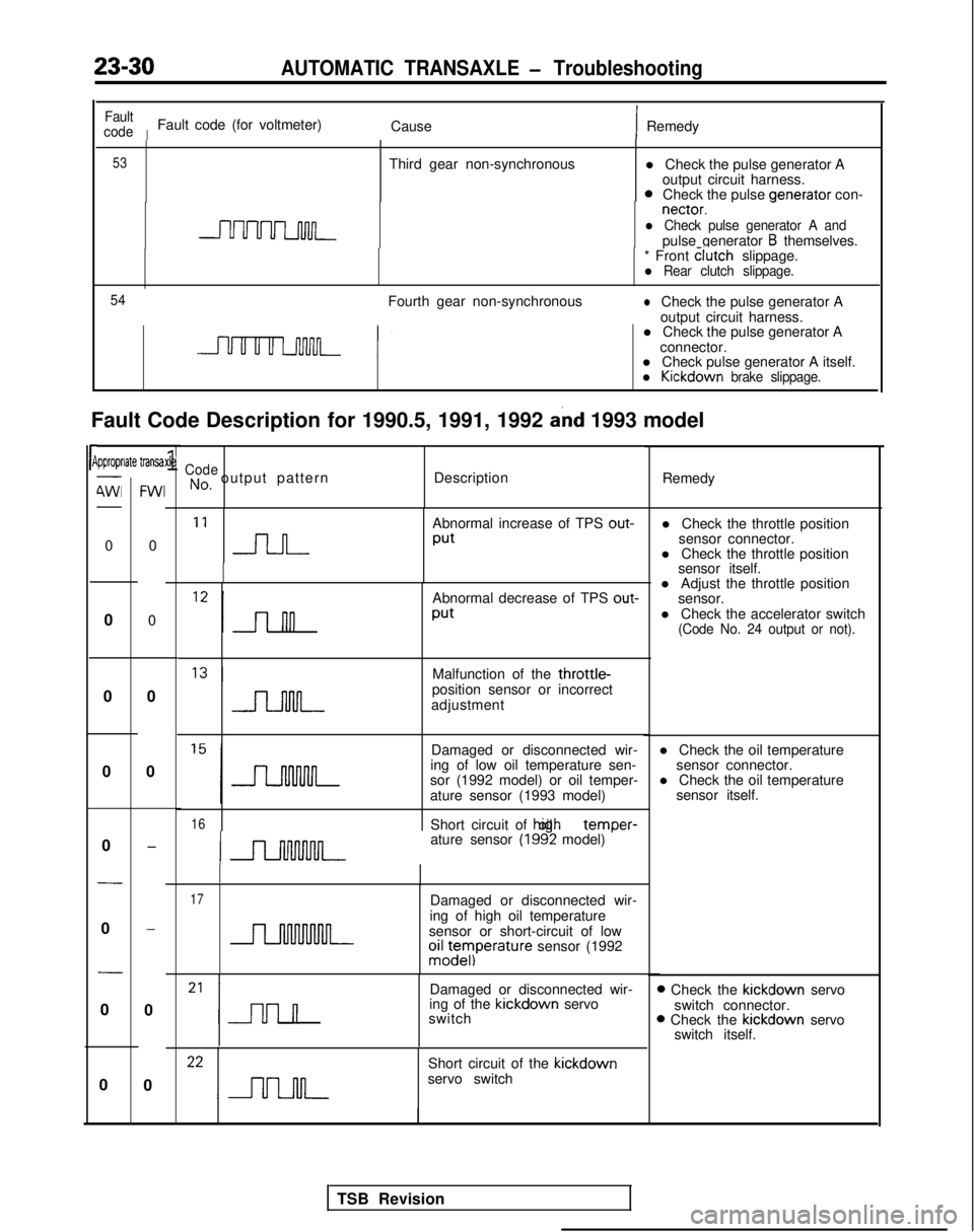
23-30AUTOMATIC TRANSAXLE - Troubleshooting
l Check the pulse generator Aoutput circuit harness.
0Check the pulse venerator
con- nectar.
-l Check pulse generator A andpulse generator B themselves.
Fault Code Description for 1990.5, 1991, 1992
and 1993 model
rP
Fault
code
IFault code (for voltmeter) CauseIRemedy
53Third gear non-synchronous
* Front clutch
slippage.
l Rear clutch slippage.
54
Fourth gear non-synchronouslCheck the pulse generator A
output circuit harness.
l Check the pulse generator A
connector.
l Check pulse generator A itself.
l Kickdown brake slippage.
ipproprlate transa-
4Wl-
0
0
0
0
0
-
0
-
0
0
FWI
0
0
0
0
-
-
0
0
xle1CodeNo, output pattern Description
Remedy
‘I n
Abnormal increase of TPS out-
Put
Abnormal decrease of TPS out-
Put
l Adjust the throttle position
sensor.
l Check the accelerator switch
(Code No. 24 output or not).
Malfunction of the throttle-position sensor or incorrect
adjustment
Damaged or disconnected wir-
ing of low oil temperature sen- l Check the oil temperature
sensor connector.
sor (1992 model) or oil temper- l Check the oil temperature
ature sensor (1993 model) sensor itself.
16Short circuit of hiah oil temDer-
ature sensor (1992 model) ’
17Damaged or disconnected wir-
ing of high oil temperature
sensor or short-circuit of low
oiz;eyIperature sensor (1992
Damaged or disconnected wir-
ing of the kickdown
servo
switch
Short circuit of the kickdown
servo switch l Check the throttle position
sensor connector.
l Check the throttle position sensor itself.
D Check the kickdown
servo
switch connector.
B Check the kickdown
servo
switch itself.
TSB Revision
Page 738 of 1273
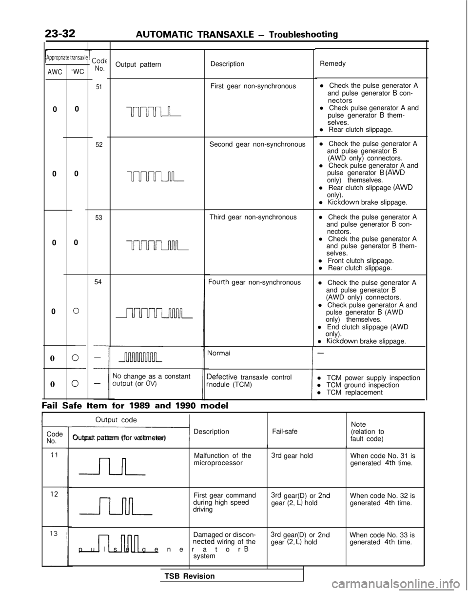
23-32AUTOMATIC TRANSAXLE
- Troubleshooting
Jipproprrate transaxCode
No.Output pattern Description
Remedy
51First gear non-synchronous
uuuul n
52Second gear non-synchronous l Check the pulse generator A
and pulse generator
B con-
nectors
l Check pulse generator A and pulse generator
B them-
selves.
l Rear clutch slippage.
l Check the pulse generator A and pulse generator
B(AWD only) connectors.
l Check pulse generator A and pulse generator
B (AWD
only) themselves.
l Rear clutch slippage (AWD
only).
l Kickdown
brake slippage.
l Check the pulse generator A and pulse generator
B con-
nectors.
l Check the pulse generator A and pulse generator
B them-
selves.
l Front clutch slippage. l Rear clutch slippage.
l Check the pulse generator A and pulse generator
B(AWD only) connectors.
l Check pulse generator A and pulse generator
B (AWD
only) themselves.
l End clutch slippage (AWD only).
l Kickdown
brake slippage.
-
l TCM power supply inspection
l TCM ground inspection
l TCM replacement
AWC‘WC
0
0 0
0
0
UUUUJ-u-l-
53Third gear non-synchronous
0
0
UUUUuwL
54Iourth gear non-synchronous
0
i
Vormal
10 change as a constantoutput (or OV)Iefective transaxle control
nodule (TCM)
0
Fail Safe
Item for
1989 and 1990 model
ri Description
Output pattern (for voltmeter) Fail-safeNote
(relation to
fault code)
Code
No.
Malfunction of the
microprocessor3rd gear hold When code No. 31 is
generated 4th
time.
First gear command
during high speed
driving
3rd gear(D) or 2ndgear (2, L) hold When code No. 32 is
generated 4th
time.
n nnn
Damaged or discon-netted wiring of the
pulse generator Bsystem
3rd gear(D) or 2ndgear (2. L) hold When code No. 33 is
generated 4th
time.
TSB Revision
Page 740 of 1273
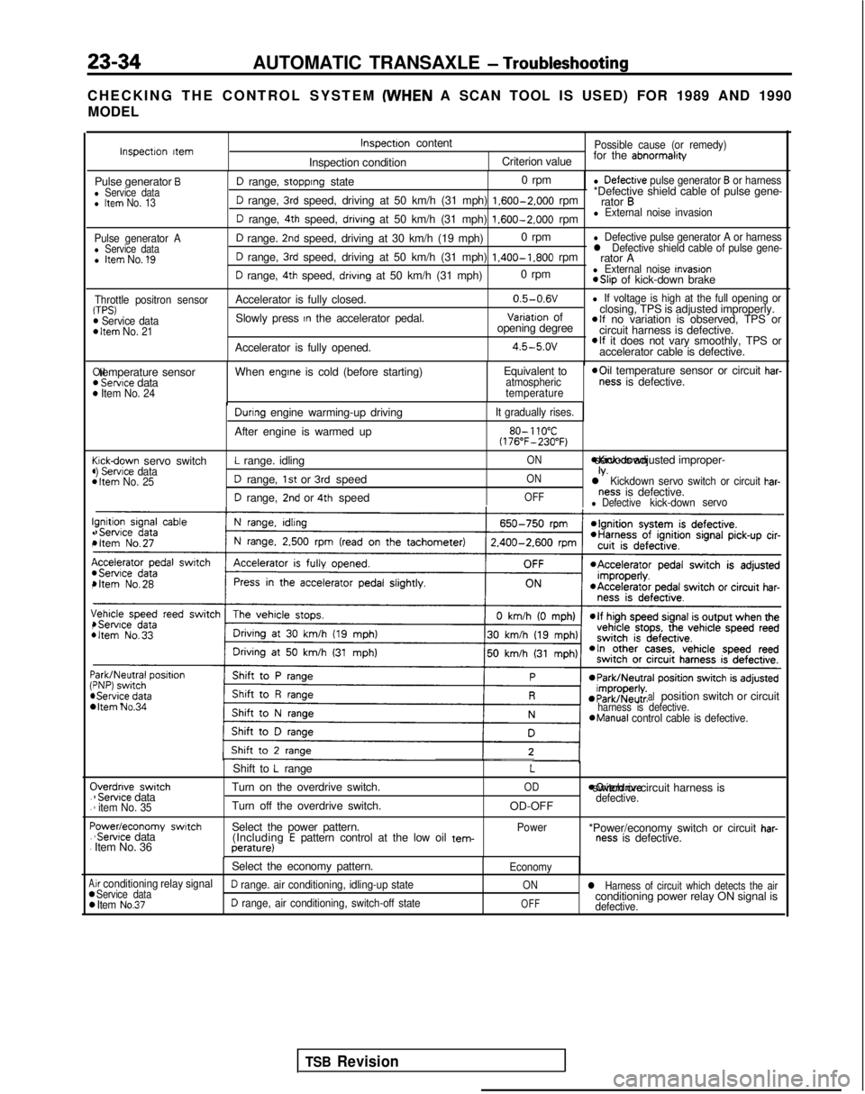
23-34AUTOMATIC TRANSAXLE - Troubleshooting
CHECKING THE CONTROL SYSTEM (WHEN
A SCAN TOOL IS USED) FOR 1989 AND 1990
MODEL
Pulse generator Al Service datal Item No. 1’9
Throttle positron sensorTPS)m Service dataD Item No. 21
I!(
(44
c44
I!.,
I(,
\,4
:44 C
.
.
F.
.
A00
D range, stopprng state 0 rpml Defectrve pulse generator B or harness
D range, 3rd speed, driving at 50 km/h (31 mph) 1.600-2.000
rpm*Defective shield cable of pulse gene-
rator B
D range, 4th speed, drivrng at 50 km/h (31 mph) 1.600-2.000
rpml External noise invasion
D range. 2nd speed, driving at 30 km/h (19 mph) 0 rpml Defective pulse generator A or harness
D range, 3rd speed, driving at 50 km/h (31 mph) 1.400-1.800
rpml Defective shield cable of pulse gene-rator A
D range, 4th speed, drivrng at 50 km/h (31 mph) 0 rpml External noise Invasion *Slip
of kick-down brake
Accelerator is fully closed. 0.5-0.6V
l If voltage is high at the full opening or
Slowly press In the accelerator pedal.Variatron of
closing, TPS is adjusted improperly.
opening degreeelf no variation is observed, TPS or
circuit harness is defective.
Accelerator is fully opened.
4.5-5.ovelf it does not vary smoothly, TPS or
accelerator cable is defective. Xl temperature sensor
) Servtce data) Item No. 24
When engtne is cold (before starting)
Equivalent toatmospheric
temperature *Oil
temperature sensor or circuit har-ness is defective.
cickdown servo switch) Servrce data1 Item No. 25
Durrng engine warming-up driving
After engine is warmed up
L range. idling
D range, 1st or 3rd speed
D range, 2nd or 4th speed
It gradually rises.
80- 110°C(176”F-230°F)
ON *Kick-down servo IS adjusted improper-
ONIV.l Kickdown servo switch or circuit har-
OFFness is defective.l Defectivekick-down
servo
bItem No.34 alposition switch or circuitharness is defective.*Manual
control cable is defective.
Iverdnve switch1 Servrce data1 item No. 35
‘owedeconomy swatch‘Servrce data
Item No. 36 Shift to
L range
Turn on the overdrive switch.
Turn off the overdrive switch.
Select the power pattern. (Including
E pattern control at the low oil tem-perature)
L
OD
OD-OFF
Power moverdrive switch or circuit harness is
defective.
*Power/economy switch or circuit har-ness is defective.
Select the economy pattern.
Economy
.ir conditioning relay signalService dataD range. air conditioning, idling-up stateONl Harness of circuit which detects the air
Item No.37D range, air conditioning, switch-off stateOFFconditioning power relay ON signal isdefective.
Inspectron ttemInspectron content
Inspection conditionPossible cause (or remedy)
Criterion value for the abnormalrty
Pulse generator Bl Service datal Item No. 13
TSB Revision